US1857061A - Automobile body - Google Patents
Automobile body Download PDFInfo
- Publication number
- US1857061A US1857061A US497293A US49729330A US1857061A US 1857061 A US1857061 A US 1857061A US 497293 A US497293 A US 497293A US 49729330 A US49729330 A US 49729330A US 1857061 A US1857061 A US 1857061A
- Authority
- US
- United States
- Prior art keywords
- vehicle
- construction
- compartment
- partition
- carrying
- Prior art date
- Legal status (The legal status is an assumption and is not a legal conclusion. Google has not performed a legal analysis and makes no representation as to the accuracy of the status listed.)
- Expired - Lifetime
Links
- 238000010276 construction Methods 0.000 description 10
- 238000005192 partition Methods 0.000 description 7
- 239000002828 fuel tank Substances 0.000 description 3
- 239000000428 dust Substances 0.000 description 2
- 241000209527 Arum Species 0.000 description 1
- 235000006481 Colocasia esculenta Nutrition 0.000 description 1
- ATJFFYVFTNAWJD-UHFFFAOYSA-N Tin Chemical compound [Sn] ATJFFYVFTNAWJD-UHFFFAOYSA-N 0.000 description 1
- NEHMKBQYUWJMIP-UHFFFAOYSA-N chloromethane Chemical compound ClC NEHMKBQYUWJMIP-UHFFFAOYSA-N 0.000 description 1
- 238000006073 displacement reaction Methods 0.000 description 1
- 239000000945 filler Substances 0.000 description 1
- 235000013305 food Nutrition 0.000 description 1
- PXUQTDZNOHRWLI-OXUVVOBNSA-O malvidin 3-O-beta-D-glucoside Chemical compound COC1=C(O)C(OC)=CC(C=2C(=CC=3C(O)=CC(O)=CC=3[O+]=2)O[C@H]2[C@@H]([C@@H](O)[C@H](O)[C@@H](CO)O2)O)=C1 PXUQTDZNOHRWLI-OXUVVOBNSA-O 0.000 description 1
- 238000004519 manufacturing process Methods 0.000 description 1
- 238000012986 modification Methods 0.000 description 1
- 230000004048 modification Effects 0.000 description 1
- 230000000284 resting effect Effects 0.000 description 1
- 230000035939 shock Effects 0.000 description 1
Images
Classifications
-
- B—PERFORMING OPERATIONS; TRANSPORTING
- B62—LAND VEHICLES FOR TRAVELLING OTHERWISE THAN ON RAILS
- B62D—MOTOR VEHICLES; TRAILERS
- B62D43/00—Spare wheel stowing, holding, or mounting arrangements
- B62D43/06—Spare wheel stowing, holding, or mounting arrangements within the vehicle body
- B62D43/08—Spare wheel stowing, holding, or mounting arrangements within the vehicle body and arranged substantially vertically
Definitions
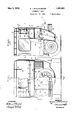
- F gure 2 is a fragmentary longitudinalsec Patented May 3, 1932 PATENT OFFICE,
- This invention relates to vehicles,and
- the invention further aims to provide an im roved vehicle body construction of the in icated character which is not undulycomplicated, which does not materially add :to the cost of production of the .bodylor increase the weight of the vehicle, and which does not detract from its appearance while greatly adding to the general eificiency thereof.
- Figure 1 s a rearview of an automobile ha 'ng a body constructed in accordance with 8$ th -invention, a -part thereof being broken away and shown in section to disclose the untio 1 view taken approximately on-the, line tin cated at 2-2 in Figure 1 of the drawin 4 igure 8 is a fragmentary sectional lan view taken'approximately on the line i vomated at 3--3-in Figure 2.
- Figure 4 1s a detail fragmentary sectional view taken approximately on the line 4-4 of Figure 2.
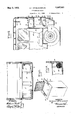
- Figure 5 is a pers ective view of one of the removable receptac es removed from the vehicle and shown in its opened condition.
- Figure 6 is a .fragmentary longitudinal sectiorial view similar to Figure 2, illustratingth application of the improved bod constructi on tca vehicle of a slightly diiibrent eferring reference to the drawings by characters of vehicle ii I and particular y to the t of ustrated in Figures 1 an 2, in
- a door 19 is hinged as at 20-and is designed to normally close the doorwa 18, to render-the storage, compartment 17 ustproof and weather tight; Obviously, the door 19 may be locked by a key actuat'ed lockto secure the articles contained in the storage compartment against theft. 7
- the door may be provided with means vfor limiting its opening movement, such as the arcuate slotted element 21 attached to the door 19 and cooperating with a pin 22 a carried by a stationary part of the vehicle.
- suitable wheel or tire supporting brackets 23 maybe provided for carrying and rigidly maintaining the same in place.
- the upper surface of the partition 16, together with the rear of the back rest 13 and the rear wall 12, defines a well or depression which opens at its upper end to the interior of the vehicle and within which suitcases, hand bags or other luggage S may be conveniently carried by resting the same on the upper surface of the partition element 16, which serves in this capacity as a platform.
- Straps or tapes 26 may be permanently attached at one end and detachably connected at the other end to extend across the upper portion of the compartment 25 for the purpose of preventing displacement of the articles S therefrom, due to road shocks and jars when the vehicle is in transit.
- hooks 27 may be suspended by flexible and elastic elements 28 from the ceilin 29 of the vehicle to engage with and ho d up-the cover of. a suitcase in the manner illustrated in dotted lines in Figure 2 whereby the occupants of the vehicle may gain access to the suitcase without the necessity of leaving the vehicle and while said suitcase is supported within the compartment 25.
- the partition 16 adjacent the opposite side walls 10 may be provided with o enin s 30,
- the receptacles 32 include a body 33 having a marginal flange 34 at the upper open end and a closure or cover 35 which is displaceable therefrom, together with a bail or handle 36 which is fulcrumed thereon to afford means for lifting the receptacle from the holder or placing the same therein.
- the receptacle may be employed for the purpose of carrying food or other contents, to which access may be gained from the interior of the vehicle without the necessity of leaving the same.
- the rear corners of the vehicle body may be provided with angularly disposed horizontal elastic strips 38 for carrying rolled articles, such assweaters, cloaks, blankets or the like.
- the body construction is shown as applied to the type of vehicle in which the fuel tank 40 is supported at the rear, and in this,
- the fuel tank may partially extend into the storage compartment 1-7 with a filler pipe 41 exposed from the rear of the compartment as illustrated.
- the construction and general arrangement are identical with that of the previously described form of the invention.
- a body fashioned to provide a carrying space in rear of the rear seat, extending from the roof to a plane below the usual bottom line of the vehicle body and across the entire width of the vehicle and a horizontal partition dis osed in a plane below that of the upper e ge of the rear seat back rest and extending therefrom to the rear wall and subdividing said carrying space into upper and lower compartments, the former being open to the interior of thebody and the latter having a doorway opening through the rear wall of the body and a door normally closing said doorway, said partition having an opening at one side of its transverse center and a receptacle holder depending from said opening into the lower compartment for the reception of a removable receptacle.
Landscapes
- Engineering & Computer Science (AREA)
- Chemical & Material Sciences (AREA)
- Combustion & Propulsion (AREA)
- Transportation (AREA)
- Mechanical Engineering (AREA)
- Body Structure For Vehicles (AREA)
Description
May 3, 1932.
*A. l. MCGLOIUGHLIIYN.
AUTOMOBILE BODY Z Sh eets-Shee t Filed Nov.
. INVENTQR Arum]. M Gurus/1.4m!
Mir /2% ATTORNEYS S May 3, 1932.
A. i. MCGLOUGHLIN AUTOMOB I LE BODY Filed Nov. 21, 2 Sheets-Sheet 2 INVENTOR ALFRED I. M fizouelu/zv WITNESSES ATTORNEYS UNITED ST I more particular, reference to snf-nnproved body construction for automob les'of the, closed model types, such as sedans, coaches; 501' the like.
l The invention broadly comprehends an un- 1 thereto is I (lerl 'ng structure. I
' F gure 2 is a fragmentary longitudinalsec Patented May 3, 1932 PATENT OFFICE,
mun I. arcenouenm, orimuw Yonx, II. If e 1 Auroxoanm noml Applloatlonmedjovember a1, 1936i sum rosters, i
This invention relates to vehicles,and
' proved body construction which, without increasing the wheel base or otherwise altering or affecting the chassis construction, 'afiord within the confines of the body, a convenient g and closed carrying space for spare tires,
wheels baggage luggage loose apparel or other articles, all of-whicli, by virtue of said bod construction, are protected against the as well as road dust or the elements, 7
while bein readily accessible when access esired. 1 The invention further aims to provide an im roved vehicle body construction of the in icated character which is not undulycomplicated, which does not materially add :to the cost of production of the .bodylor increase the weight of the vehicle, and which does not detract from its appearance while greatly adding to the general eificiency thereof.
With the above recited and other objects in view, reference is had to the following.
description and accompanying drawings, in which there :are. exhibited several examples or embodiments of the invention, while the claims define the actual scope ofthe same. In .thedrawings: 1
Figure 1 s a rearview of an automobile ha 'ng a body constructed in accordance with 8$ th -invention, a -part thereof being broken away and shown in section to disclose the untio 1 view taken approximately on-the, line tin cated at 2-2 in Figure 1 of the drawin 4 igure 8 is a fragmentary sectional lan view taken'approximately on the line i ridicated at 3--3-in Figure 2.
i Figure 4 1s a detail fragmentary sectional view taken approximately on the line 4-4 of Figure 2.
Figure 5 is a pers ective view of one of the removable receptac es removed from the vehicle and shown in its opened condition.
Figure 6 is a .fragmentary longitudinal sectiorial view similar to Figure 2, illustratingth application of the improved bod constructi on tca vehicle of a slightly diiibrent eferring reference to the drawings by characters of vehicle ii I and particular y to the t of ustrated in Figures 1 an 2, in
which the fuel tank is arranged at a point l .thereon' at the rear-of the vehicle, the im-: 1
proved body construction consists in extend jingtlie side walls 10;rearwardly beyond the .rea-rseat -11 so as to-space the rear wall 12 of Y the body an ap reciable distance be ond the 1 backrest 13 o the rear seat 11. he side Walls 10 and the rear wall .12 are also extendeddownwardly a greater distance than I ordinarily and are' connected'with or merge wall .12 is formed with an opening 18 constituting a doorway for gaining access to the storage compartment 17 for introducing the tires, wheels or other articles thereto or removing thesame therefrom. A door 19 is hinged as at 20-and is designed to normally close the doorwa 18, to render-the storage, compartment 17 ustproof and weather tight; Obviously, the door 19 may be locked by a key actuat'ed lockto secure the articles contained in the storage compartment against theft. 7
In practice, the door may be provided with means vfor limiting its opening movement, such as the arcuate slotted element 21 attached to the door 19 and cooperating with a pin 22 a carried by a stationary part of the vehicle.
Within the storage compartment 17, suitable wheel or tire supporting brackets 23 maybe provided for carrying and rigidly maintaining the same in place.
r lrectly in real theback rest 13 of the rear and the partition 16, together with I 1 The upper surface of the partition 16, together with the rear of the back rest 13 and the rear wall 12, defines a well or depression which opens at its upper end to the interior of the vehicle and within which suitcases, hand bags or other luggage S may be conveniently carried by resting the same on the upper surface of the partition element 16, which serves in this capacity as a platform. Straps or tapes 26 may be permanently attached at one end and detachably connected at the other end to extend across the upper portion of the compartment 25 for the purpose of preventing displacement of the articles S therefrom, due to road shocks and jars when the vehicle is in transit. -If desirable, hooks 27 may be suspended by flexible and elastic elements 28 from the ceilin 29 of the vehicle to engage with and ho d up-the cover of. a suitcase in the manner illustrated in dotted lines in Figure 2 whereby the occupants of the vehicle may gain access to the suitcase without the necessity of leaving the vehicle and while said suitcase is supported within the compartment 25.
The partition 16 adjacent the opposite side walls 10 may be provided with o enin s 30,
p from which receptacle holders 31 epen into the unoccupied space of the storage compartment17, and which receptacle holders may receive receptacles such as indicated by the reference character 32. As shown, the receptacles 32 include a body 33 having a marginal flange 34 at the upper open end and a closure or cover 35 which is displaceable therefrom, together with a bail or handle 36 which is fulcrumed thereon to afford means for lifting the receptacle from the holder or placing the same therein. The receptacle may be employed for the purpose of carrying food or other contents, to which access may be gained from the interior of the vehicle without the necessity of leaving the same.
As a further feature, the rear corners of the vehicle bodymay be provided with angularly disposed horizontal elastic strips 38 for carrying rolled articles, such assweaters, cloaks, blankets or the like.
As illustrated in Figure 6 of the drawings, the body construction is shown as applied to the type of vehicle in which the fuel tank 40 is supported at the rear, and in this,
' instance the fuel tank may partially extend into the storage compartment 1-7 with a filler pipe 41 exposed from the rear of the compartment as illustrated. In other respects, the construction and general arrangement are identical with that of the previously described form of the invention.
From the fore oing, it will thus be seen that an improved ody construction for automobiles such as sedans or coaches has been devised, by virtue 0 which a convenient and protected against theft, as well as road dust or the elements.
While there have been illustrated and dethe invention, it is to be clearly understood that no limitation is intended to the precise structural details, but that variations and modifications which properly fall within the scope of the appended claims may be resorted to when found expedient.
What is claimed is:
1. In an automobile of the sedantype, a body fashioned to provide a carrying space in rear of the rear seat, extending from the roof to a plane below the usual bottom line of the vehicle body and across the entire width of the vehicle and a horizontal partition dis osed in a plane below that of the upper e ge of the rear seat back rest and extending therefrom to the rear wall and subdividing said carrying space into upper and lower compartments, the former being open to the interior of thebody and the latter having a doorway opening through the rear wall of the body and a door normally closing said doorway, said partition having an opening at one side of its transverse center and a receptacle holder depending from said opening into the lower compartment for the reception of a removable receptacle.
2. In an automobile bod construction of the sedan type, means defining an article carrying space disposed in rear of the rear seat,
extending from the roof to a point below the usual bottom line of the vehicle body and across the complete width of said, vehicle and a horizontal partition disposed in a plane below that of the edge of the rear seat back rest and subdividing said carrying space into upper and lower compartmentathe uppercompartment being open to the interior of the body and one of the lower compartments being positioned at the transverse center of the body for the storage of tires and/or .wheels and ada ted to be opened to the exclosed carrying s ace or spaces are afforded for various artic es, whereby the same are
Priority Applications (1)
| Application Number | Priority Date | Filing Date | Title |
|---|---|---|---|
| US497293A US1857061A (en) | 1930-11-21 | 1930-11-21 | Automobile body |
Applications Claiming Priority (1)
| Application Number | Priority Date | Filing Date | Title |
|---|---|---|---|
| US497293A US1857061A (en) | 1930-11-21 | 1930-11-21 | Automobile body |
Publications (1)
| Publication Number | Publication Date |
|---|---|
| US1857061A true US1857061A (en) | 1932-05-03 |
Family
ID=23976259
Family Applications (1)
| Application Number | Title | Priority Date | Filing Date |
|---|---|---|---|
| US497293A Expired - Lifetime US1857061A (en) | 1930-11-21 | 1930-11-21 | Automobile body |
Country Status (1)
| Country | Link |
|---|---|
| US (1) | US1857061A (en) |
Cited By (3)
| Publication number | Priority date | Publication date | Assignee | Title |
|---|---|---|---|---|
| FR2839938A1 (en) * | 2002-05-24 | 2003-11-28 | Renault Sa | ARRANGEMENT OF THE REAR PART OF A MOTOR VEHICLE COMPRISING A BOX FOR STORING A SPARE WHEEL |
| US7104583B2 (en) | 1995-07-26 | 2006-09-12 | Scott Clare | Vehicle with storage/utility system |
| US7461884B2 (en) * | 1995-07-26 | 2008-12-09 | Scott Clare | Storage system for vehicles |
-
1930
- 1930-11-21 US US497293A patent/US1857061A/en not_active Expired - Lifetime
Cited By (3)
| Publication number | Priority date | Publication date | Assignee | Title |
|---|---|---|---|---|
| US7104583B2 (en) | 1995-07-26 | 2006-09-12 | Scott Clare | Vehicle with storage/utility system |
| US7461884B2 (en) * | 1995-07-26 | 2008-12-09 | Scott Clare | Storage system for vehicles |
| FR2839938A1 (en) * | 2002-05-24 | 2003-11-28 | Renault Sa | ARRANGEMENT OF THE REAR PART OF A MOTOR VEHICLE COMPRISING A BOX FOR STORING A SPARE WHEEL |
Similar Documents
| Publication | Publication Date | Title |
|---|---|---|
| US3471070A (en) | Automotive bumper providing articles storage space | |
| US5316358A (en) | Integral storage container for pick-up truck | |
| US4087126A (en) | Console for van-type vehicles | |
| US3881768A (en) | Pickup truck bed liner and protector | |
| US3215323A (en) | Car trunk lid carrier | |
| US7281742B2 (en) | Vehicle compartment divider | |
| US4756457A (en) | Cargo and storage apparatus for vans and like vehicles | |
| US1675701A (en) | Freight truck | |
| US3365084A (en) | Utility car trunk | |
| US2603527A (en) | Spare tire carrier for vehicles | |
| US1404484A (en) | Chest for motor vehicles | |
| US1857061A (en) | Automobile body | |
| US3653567A (en) | Portable kit | |
| US1490538A (en) | Utility receptacle and armrest | |
| US2175528A (en) | Rear part of automobiles with rear engines | |
| US1237750A (en) | Tool-case for automobiles. | |
| US2043858A (en) | Protector cover for trucks | |
| US1279635A (en) | Truck attachment for automobiles. | |
| US2321239A (en) | Spare tire and luggage compartment for vehicle bodies | |
| US2005604A (en) | Tool chest and spare wheel carrier for automobiles | |
| JP3707243B2 (en) | Car trim | |
| US2091076A (en) | Wheel and tire carrier | |
| US3362745A (en) | Camping trailer | |
| US2115779A (en) | Vehicle luggage and spare tire closure | |
| US2140615A (en) | Tire carrier and body construction |