US1857059A - Device for miniature golf courses - Google Patents
Device for miniature golf courses Download PDFInfo
- Publication number
- US1857059A US1857059A US491050A US49105030A US1857059A US 1857059 A US1857059 A US 1857059A US 491050 A US491050 A US 491050A US 49105030 A US49105030 A US 49105030A US 1857059 A US1857059 A US 1857059A
- Authority
- US
- United States
- Prior art keywords
- lever
- receptacle
- shaft
- golf courses
- golf ball
- Prior art date
- Legal status (The legal status is an assumption and is not a legal conclusion. Google has not performed a legal analysis and makes no representation as to the accuracy of the status listed.)
- Expired - Lifetime
Links
- 239000004576 sand Substances 0.000 description 3
- 229910000831 Steel Inorganic materials 0.000 description 1
- 230000001419 dependent effect Effects 0.000 description 1
- 239000000463 material Substances 0.000 description 1
- 239000002184 metal Substances 0.000 description 1
- 238000012986 modification Methods 0.000 description 1
- 230000004048 modification Effects 0.000 description 1
- 239000002674 ointment Substances 0.000 description 1
- 239000010959 steel Substances 0.000 description 1
- 239000002023 wood Substances 0.000 description 1
Images
Classifications
-
- A—HUMAN NECESSITIES
- A63—SPORTS; GAMES; AMUSEMENTS
- A63B—APPARATUS FOR PHYSICAL TRAINING, GYMNASTICS, SWIMMING, CLIMBING, OR FENCING; BALL GAMES; TRAINING EQUIPMENT
- A63B67/00—Sporting games or accessories therefor, not provided for in groups A63B1/00 - A63B65/00
- A63B67/02—Special golf games, e.g. miniature golf ; Putting tracks therefor
Definitions
- This invention relates to new and novel 1 features in games and more particularly in games wherein a golf ball is impelled b an I ordinary golf club with the customary orce as on regular golf courses.
- One object of this invention is to provide a game apparatus of this type to be used 111 ,-conjunction with miniature golf courses,
- Another object of the invention is to provide an indicating means inconjunction-With the game apparatus, adapted to show the distance the golf ball would travel, if the flight of the said ball was not arrested by the game apparatus.
- a further object of the invention is to provide an apparatus which is equally effective in the practice of regular golf shots.
- the invention further resides in certain.
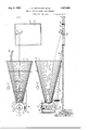
- Figure 1 is a plan view of t e apparatus showing the golf ball receiver and the rela-- tive position of the tee in conjunction there- %ig. 3 is an end elevation of the golf ball receiving apparatus shown in Fig. 1;
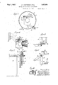
- Fig. 4 is a side elevation showing the indi-- the indicating terial, and held in conical relation preferably as a game or as a device adapted to be used by rings 3 of metal or other suitable material.
- the coneelements 2 are each secured 'to the rings 3 byany suitable means such asri'vets.
- the conical section 1 is mounted upon supports 4 adapted to be. positioned adjacent the,
- the rear or apex end of the conel is supported by means of an adjustable jack 5, in such a manner that the axis of the cone 1 from the base. to the vertex will lie in a plane substantially parallel with the ground, or may be placed at an angle with the ground thereby affording a steep angle for a mashie shot or a relatively flat angle for a midiron shot as the player desires.
- a tubular receptacle 6 composed of verti-" cal elements -7 made of wood or other suit-able materialhas a circular opening cut in the side surface thereof.
- the rear or vertex end of the cone 1 extends into the said opening and is securely fastened to the receptacle.
- the receptacle 6 in the present instance is provided with a cover 8, the said cover in the present instance having a hand hole 9 there- .m, closed by a lid 10.
- the bottom or base 110i the receptacle is in the form of an inverted conical frustrum and in the present instance has a hole 12 in the vertex thereof to allow the ball to roll out of the receptacle.
- Bearings 13 aresecurely mounted in the sides of the receptacle 6 at a point near the top thereof.
- a shaft 14 is rotatably mounted in the bearings 13 and extends entirely through the bearings 13 to the exterior of the receptacle 6.
- An arresting or stopping member 15 is rigidly mounted on the shaft 14 within the said receptacle 6' opposite the opencured to one end of the said shaft 14 -exterior of the receptacle, the lever '16 and the stop the inmember 15 preferably lying in the sameplanel 7
- Connected to the lever 16 and to the receptacle is a spring 17 tending to oppose any force on the stop 15, to rotate the shaft 14 and the lever 16 in a clockwise direction.
- the spring 17 is of such strength that it will permit a clockwise rotation of the shaft and lever when a suflicient force is exerted on the stop 15.
- Projecting from the lever 16 is a pin 18 which lies in the path of a second ATEN O F CE "ing of the conical section, the lever 16 is se- -z lever 19 rotatably mounted upon the shaft 14.
- a sufficient force on the sto 15 causes the rotation of the shaft M an the lever 16 and pin 18 on the lever 16 engages the lever 19 and rotates it about the shaft 14.
- the lever 19 is adapted to contact with the contact points 20 and completes anelectric circuit t rough wires 21 and thereby lighting the indicating lamps 22.
- the contact points 20 are mounted upon a base 23, which is in turn mounted on the side of the receptacle 6 in any well known manner.
- the contact point upon which the lever 19 comes to rest is dependent upon the force on the stop 15 which causes a relative degree of rotation of the shaft 14 and the lever 16, against the resisting force of the spring 17.
- the lever 19 will remain in contact and complete the electric circuit to the lamps after the spring 17 has returned the lever 16 to its normal osition.
- a string 24 isprovided and attached to the lever 19 whereby the player may give the lever 19 a counter-clockwise rotation to its 25 normal position, breaking the electric circuit.
- an inclined trough 25 directly beneath the hole 12 in the base'of the receptacle 6 is an inclined trough 25, supported beneath the hole 12 on a suitable support, 26, the said so trough 25 is adapted to extend to a position preferably adjacent the tee from which the golf ball is impelled.
- a tee is provided consistingof a soft rubber housing 27 mounted on a steel base 28 and 85 having a tubular member 29 adapted to extend u ward through the housing 27.
- the inner iameter of the member 29 is sufficient to support an ordinary golf ball 30.
- the housing 27 and the base 28 are embedded in sand 31 which is enclosed by side and end members 32, the housin 25 being embedded in the sand 31 to sucha epth that the tubular tee member 29 will extend upward through the upper surface of the sand bed 31.
- the player places a olf ball 30 upon the tubular tee 29 and impefi a full hard stroke, through the hollow cone 1 and into the receptacle 6.
- the golf ball entering the receptacle 6 hits the stop 15 with sufficient impact to cause the stop to rotate the shaft 14 and the lever 16 against the resisting tension of the spring 17.
- a game apparatus comprising a conical member, composed of a luralit of Ion 'tudlnal staves, and adapted to gui e a golfi all, a tubular receptacle composed of a plurality of longitudinal staves and havin a top and bottom thereon and adapted to be securely mounted on the conical member at the apex thereof; means within said receptacle for arresting the flight of a golf ball, and means operative in con unction with the said arresting means for indicatin the distance of an uninterrupted flight of t e golf ball, the said indicating means being mounted on the exterior of the said receptacle.
- a game apparatus comprising a conical member, a tubular receptacle mounted at the apex thereof, a shaft rotatably mounted in and extending external] of the receptacle, means mounted on the s aft and within the receptacle for arresting the flight of a golf .ball, and indicating means mounted externally of the receptacle and operative in conjunction with the arresting means, the said indicating means comprising a lever rigidly mounted on the said shaft, the said lever hav-v ing a pin, a second lever lying in the path of the pin, a plurality of contact points in operable relation with said second lever forcompleting electric circuits when the second lever is rotated by the pin on said first lever, the second lever is adapted to remain in con tact with the point until manually returned to normal position.
Landscapes
- Health & Medical Sciences (AREA)
- General Health & Medical Sciences (AREA)
- Physical Education & Sports Medicine (AREA)
- Toys (AREA)
Description
J; HuMATHESON ET AL DEVICE FOR MINIATURE GOLF COURSES May 3, 1932.
2 Sheets-Sheet 1 Filed Oct. 24, 1930 May 3, 1932.
J. H. MATHESON ET AL 1,857,059 DEVICE-FOR MINIATURE GOLF COURSES Filed Oct. .24, 1930 2 Sheets-Sheet M W Z M 0 v with;
Patented May 3, 1932 it UNITED STATES JAMES H. mrnnson am: DONALD 1:. nnrnnso'u, or nnenwoon, rnunsxnvann nnvrongoa nmxarunn oonroounsns. f
Application filed mama-1930.: seine No. 491,050.
This invention relates to new and novel 1 features in games and more particularly in games wherein a golf ball is impelled b an I ordinary golf club with the customary orce as on regular golf courses.
. One object of this invention is to provide a game apparatus of this type to be used 111 ,-conjunction with miniature golf courses,
preferably at the first and eighteenth holes, and thereby enable the players to start off and finish the game with'the full and hard ordinary driving stroke.
Another object of the invention is to provide an indicating means inconjunction-With the game apparatus, adapted to show the distance the golf ball would travel, if the flight of the said ball was not arrested by the game apparatus. y
A further object of the invention is to provide an apparatus which is equally effective in the practice of regular golf shots.
The invention further resides in certain.
structural features hereinafter set forth.
In the accompanying drawin s: Figure 1 is a plan view of t e apparatus showing the golf ball receiver and the rela-- tive position of the tee in conjunction there- %ig. 3 is an end elevation of the golf ball receiving apparatus shown in Fig. 1;
Fig. 4 is a side elevation showing the indi-- the indicating terial, and held in conical relation preferably as a game or as a device adapted to be used by rings 3 of metal or other suitable material. The coneelements 2 are each secured 'to the rings 3 byany suitable means such asri'vets.
- The conical section 1 is mounted upon supports 4 adapted to be. positioned adjacent the,
forward or base end of the cone 1. The rear or apex end of the conel is supported by means of an adjustable jack 5, in such a manner that the axis of the cone 1 from the base. to the vertex will lie in a plane substantially parallel with the ground, or may be placed at an angle with the ground thereby affording a steep angle for a mashie shot or a relatively flat angle for a midiron shot as the player desires.
A tubular receptacle 6 composed of verti-" cal elements -7 made of wood or other suit-able materialhas a circular opening cut in the side surface thereof. The rear or vertex end of the cone 1 extends into the said opening and is securely fastened to the receptacle. The receptacle 6 in the present instance is provided with a cover 8, the said cover in the present instance having a hand hole 9 there- .m, closed by a lid 10. The bottom or base 110i the receptacle is in the form of an inverted conical frustrum and in the present instance has a hole 12 in the vertex thereof to allow the ball to roll out of the receptacle. Bearings 13 aresecurely mounted in the sides of the receptacle 6 at a point near the top thereof. A shaft 14 is rotatably mounted in the bearings 13 and extends entirely through the bearings 13 to the exterior of the receptacle 6. An arresting or stopping member 15 is rigidly mounted on the shaft 14 within the said receptacle 6' opposite the opencured to one end of the said shaft 14 -exterior of the receptacle, the lever '16 and the stop the inmember 15 preferably lying in the sameplanel 7 Connected to the lever 16 and to the receptacle is a spring 17 tending to oppose any force on the stop 15, to rotate the shaft 14 and the lever 16 in a clockwise direction. The spring 17 is of such strength that it will permit a clockwise rotation of the shaft and lever when a suflicient force is exerted on the stop 15. Projecting from the lever 16 is a pin 18 which lies in the path of a second ATEN O F CE "ing of the conical section, the lever 16 is se- -z lever 19 rotatably mounted upon the shaft 14. Thus a sufficient force on the sto 15 causes the rotation of the shaft M an the lever 16 and pin 18 on the lever 16 engages the lever 19 and rotates it about the shaft 14. The lever 19 is adapted to contact with the contact points 20 and completes anelectric circuit t rough wires 21 and thereby lighting the indicating lamps 22. The contact points 20 are mounted upon a base 23, which is in turn mounted on the side of the receptacle 6 in any well known manner. The contact point upon which the lever 19 comes to rest is dependent upon the force on the stop 15 which causes a relative degree of rotation of the shaft 14 and the lever 16, against the resisting force of the spring 17. The lever 19 will remain in contact and complete the electric circuit to the lamps after the spring 17 has returned the lever 16 to its normal osition.
A string 24 isprovided and attached to the lever 19 whereby the player may give the lever 19 a counter-clockwise rotation to its 25 normal position, breaking the electric circuit.
In the present instance, directly beneath the hole 12 in the base'of the receptacle 6 is an inclined trough 25, supported beneath the hole 12 on a suitable support, 26, the said so trough 25 is adapted to extend to a position preferably adjacent the tee from which the golf ball is impelled.
A tee is provided consistingof a soft rubber housing 27 mounted on a steel base 28 and 85 having a tubular member 29 adapted to extend u ward through the housing 27. The inner iameter of the member 29 is sufficient to support an ordinary golf ball 30. The housing 27 and the base 28 are embedded in sand 31 which is enclosed by side and end members 32, the housin 25 being embedded in the sand 31 to sucha epth that the tubular tee member 29 will extend upward through the upper surface of the sand bed 31.
In playing the game: y
The player places a olf ball 30 upon the tubular tee 29 and impefi a full hard stroke, through the hollow cone 1 and into the receptacle 6. The golf ball entering the receptacle 6 hits the stop 15 with sufficient impact to cause the stop to rotate the shaft 14 and the lever 16 against the resisting tension of the spring 17. The
rotation of the lever 16 causes the pin 18 on the lever 16 to engage the lever 19 and rotate ls the golf ball, with lever 19 to the contact point which completes the circuit to the indicating lamp signifying a olf shot of that distance.
t will be apparent that certain modifications and changes may be made hereto withoutv departing from the invention.
We claim:
1. A game apparatus comprising a conical member, composed of a luralit of Ion 'tudlnal staves, and adapted to gui e a golfi all, a tubular receptacle composed of a plurality of longitudinal staves and havin a top and bottom thereon and adapted to be securely mounted on the conical member at the apex thereof; means within said receptacle for arresting the flight of a golf ball, and means operative in con unction with the said arresting means for indicatin the distance of an uninterrupted flight of t e golf ball, the said indicating means being mounted on the exterior of the said receptacle.
2. A game apparatus comprising a conical member, a tubular receptacle mounted at the apex thereof, a shaft rotatably mounted in and extending external] of the receptacle, means mounted on the s aft and within the receptacle for arresting the flight of a golf .ball, and indicating means mounted externally of the receptacle and operative in conjunction with the arresting means, the said indicating means comprising a lever rigidly mounted on the said shaft, the said lever hav-v ing a pin, a second lever lying in the path of the pin, a plurality of contact points in operable relation with said second lever forcompleting electric circuits when the second lever is rotated by the pin on said first lever, the second lever is adapted to remain in con tact with the point until manually returned to normal position.
JAMES H. MATHESON. DONALD E. MATHESON.
the said lever 19 about the shaft 14 and into contact with one of the contact points 20.
, 65 the pin 18 on the lever 16 to rotate the. contact
Priority Applications (1)
| Application Number | Priority Date | Filing Date | Title |
|---|---|---|---|
| US491050A US1857059A (en) | 1930-10-24 | 1930-10-24 | Device for miniature golf courses |
Applications Claiming Priority (1)
| Application Number | Priority Date | Filing Date | Title |
|---|---|---|---|
| US491050A US1857059A (en) | 1930-10-24 | 1930-10-24 | Device for miniature golf courses |
Publications (1)
| Publication Number | Publication Date |
|---|---|
| US1857059A true US1857059A (en) | 1932-05-03 |
Family
ID=23950585
Family Applications (1)
| Application Number | Title | Priority Date | Filing Date |
|---|---|---|---|
| US491050A Expired - Lifetime US1857059A (en) | 1930-10-24 | 1930-10-24 | Device for miniature golf courses |
Country Status (1)
| Country | Link |
|---|---|
| US (1) | US1857059A (en) |
Cited By (5)
| Publication number | Priority date | Publication date | Assignee | Title |
|---|---|---|---|---|
| US2863667A (en) * | 1955-04-25 | 1958-12-09 | Willard E Batts | Game device |
| US3081633A (en) * | 1958-09-03 | 1963-03-19 | Soden Adolph F Graf Von | Golf tower apparatus and the like |
| US3390882A (en) * | 1966-02-09 | 1968-07-02 | Herbert L. Megerle | Portable golf driving range including hinge means connecting self-supporting panels |
| US3720413A (en) * | 1971-03-29 | 1973-03-13 | A Ready | Game target |
| US5823885A (en) * | 1996-11-25 | 1998-10-20 | Stempfer; Frank N. | Portable personal driving range and all purpose sporting net |
-
1930
- 1930-10-24 US US491050A patent/US1857059A/en not_active Expired - Lifetime
Cited By (5)
| Publication number | Priority date | Publication date | Assignee | Title |
|---|---|---|---|---|
| US2863667A (en) * | 1955-04-25 | 1958-12-09 | Willard E Batts | Game device |
| US3081633A (en) * | 1958-09-03 | 1963-03-19 | Soden Adolph F Graf Von | Golf tower apparatus and the like |
| US3390882A (en) * | 1966-02-09 | 1968-07-02 | Herbert L. Megerle | Portable golf driving range including hinge means connecting self-supporting panels |
| US3720413A (en) * | 1971-03-29 | 1973-03-13 | A Ready | Game target |
| US5823885A (en) * | 1996-11-25 | 1998-10-20 | Stempfer; Frank N. | Portable personal driving range and all purpose sporting net |
Similar Documents
| Publication | Publication Date | Title |
|---|---|---|
| US5316310A (en) | Disc toss game | |
| US1935370A (en) | Game apparatus | |
| US2121270A (en) | Putting game | |
| US2370529A (en) | Golf ball teeing device | |
| US1857059A (en) | Device for miniature golf courses | |
| US3380738A (en) | Batting practice device | |
| US1785876A (en) | Catapult | |
| US3647219A (en) | Golf-practicing apparatus | |
| US2635879A (en) | Simulated golf cup | |
| US3966212A (en) | Simulated golf green | |
| US1776161A (en) | Ejecting device | |
| US2641932A (en) | Golf game and practice apparatus | |
| US2279857A (en) | Aiming and projecting play apparatus | |
| US2032677A (en) | Game | |
| US1531105A (en) | Device for playing pussy or ball | |
| US3539186A (en) | Combined lift stick and ball | |
| US1788336A (en) | Weight-operated switch | |
| US1391306A (en) | Game | |
| US1242046A (en) | Base-ball game. | |
| US1964232A (en) | Combination ball bat and catcher | |
| US3468535A (en) | Scoring device | |
| US3145992A (en) | Game apparatus comprising successively playable goals with ball transfer means therebetween | |
| US1547881A (en) | Ball-throwing game | |
| US2186337A (en) | Game apparatus | |
| US20170291083A1 (en) | Golf Game Assembly |