US1857049A - Magnetic axle puller - Google Patents
Magnetic axle puller Download PDFInfo
- Publication number
- US1857049A US1857049A US481749A US48174930A US1857049A US 1857049 A US1857049 A US 1857049A US 481749 A US481749 A US 481749A US 48174930 A US48174930 A US 48174930A US 1857049 A US1857049 A US 1857049A
- Authority
- US
- United States
- Prior art keywords
- handle
- core
- coil
- magnetic axle
- inner end
- Prior art date
- Legal status (The legal status is an assumption and is not a legal conclusion. Google has not performed a legal analysis and makes no representation as to the accuracy of the status listed.)
- Expired - Lifetime
Links
- XEEYBQQBJWHFJM-UHFFFAOYSA-N Iron Chemical compound [Fe] XEEYBQQBJWHFJM-UHFFFAOYSA-N 0.000 description 4
- 238000004804 winding Methods 0.000 description 3
- 238000010276 construction Methods 0.000 description 2
- 229910052742 iron Inorganic materials 0.000 description 2
- 239000000835 fiber Substances 0.000 description 1
- 230000004048 modification Effects 0.000 description 1
- 238000012986 modification Methods 0.000 description 1
- 239000005060 rubber Substances 0.000 description 1
- 239000000126 substance Substances 0.000 description 1
- 239000002023 wood Substances 0.000 description 1
Images
Classifications
-
- B—PERFORMING OPERATIONS; TRANSPORTING
- B25—HAND TOOLS; PORTABLE POWER-DRIVEN TOOLS; MANIPULATORS
- B25B—TOOLS OR BENCH DEVICES NOT OTHERWISE PROVIDED FOR, FOR FASTENING, CONNECTING, DISENGAGING OR HOLDING
- B25B11/00—Work holders not covered by any preceding group in the subclass, e.g. magnetic work holders, vacuum work holders
- B25B11/002—Magnetic work holders
-
- B—PERFORMING OPERATIONS; TRANSPORTING
- B25—HAND TOOLS; PORTABLE POWER-DRIVEN TOOLS; MANIPULATORS
- B25B—TOOLS OR BENCH DEVICES NOT OTHERWISE PROVIDED FOR, FOR FASTENING, CONNECTING, DISENGAGING OR HOLDING
- B25B27/00—Hand tools, specially adapted for fitting together or separating parts or objects whether or not involving some deformation, not otherwise provided for
- B25B27/02—Hand tools, specially adapted for fitting together or separating parts or objects whether or not involving some deformation, not otherwise provided for for connecting objects by press fit or detaching same
Definitions
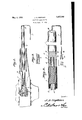
- Figure 1 shows in side elevation, a device constructed in accordance with the invention, parts being broken away, the structure being in the position of use;
- Figure 2 is a longitudinal section, wherein parts are in elevation, portions being broken away;
- Figure 3 is a fragmental elevation showing a modification.
- a handle 1 preferably of circular cross-section, and of any desired length.
- the handle 1 may be made of wood, fiber, rubber or any other insulating substance.
- the handle 1 is supplied with superficial longitudinal grooves 2, which extend the whole length of the handle 1.
- the numeral 5 designates a core of less diameter than the handle 1 and preferably of circular cross-section.
- the core 1 has a reduced end 5 which is mounted in the socket 3 of the handle 1 and is secured therein, therear end of the core abutting against the forward end of the handle 1.
- the core 4 is made of soft iron so that it can be magnetized readily, and if desired, the core may be composed of a plurality of small iron wires 6, laid side by side and compacted into a cylinder, as indicated in Figure 3 of the drawings.
- the body of a coil 7 which abuts against the forward end of the handle 1.
- the end 8 of the coil 7 is set back a little from the end of the core 4, so that the end of the core 4 will project and protect the end 8 of the coil 7.
- the terminals 9 of the coil? extend backwardly along the grooves 2 of the handle and are secured in the said grooves.
- the terminals 9 of the coil 7 converge, as shown at 10, and are encased in a flexible tubular sheath 11, from which the ends of the termianls 9 emerge, as shown at 12 in Figure 2.
- the terminals of the coil are connected by any suitable means 14: with thepoles ofa battery 15,
- the core 4 when the coil 7 is energized, the core 4 will act as a magnet, attracting and holding anyobjects capable of being attracted and held bya magnet, The
- structure may be used for a wide variety of purposes. .Thus it may be introduced into the axle 16 of a motor vehicle, to remove a broken part, shown'at 17. A mechanic will find many other uses for the device.
- a magnetic fishing tool characterized by ease of assembly, and comprising a rod-like handle and a coil, the coil comprising a core and a winding that forms a body about the core, the inner end of the core projecting I 7 beyond the inner end 'ofthe body, the wind ing being formed into a cable beyond the outer end of the handle, and that portion of the winding that is between the cable and the body being in the form of a loop, the handle having a socket in its inner end, and oppositely-disposed straight grooves 011 1ts outer surface, the loop being capable of being opened dle, with said end of the core mounted in the socket of the handle, the inner end of the handle being of substantially the same area and diameter as the body, and being in abutment with the inner end of the body, to
Landscapes
- Engineering & Computer Science (AREA)
- Mechanical Engineering (AREA)
- Electromagnets (AREA)
Description
May 3, 1932.
J. D. HOPKINS MAGNETIC AXLE FULLER Filed Sept. 13. 1930 Patented May 3, 1932 UNITED STATES PATENT, OFFICE JAMES DAUG-HERTY HOPKINS, OF MIDWAY, KENTUCKY MAGNETIC AXLE FULLER Application filed September 13, 1930. Serial No. 481,749.
' which will appear as the description proceeds, the invention resides in the combination and arrangement of parts and in the details of construction hereinafter described and claimed, it being understood that changes in the precise embodiment of the invention herein disclosed may be made within the scope of what is claimed without departing from the spirit of the invention.
In the accompanying drawings:
Figure 1 shows in side elevation, a device constructed in accordance with the invention, parts being broken away, the structure being in the position of use;
Figure 2 is a longitudinal section, wherein parts are in elevation, portions being broken away;
Figure 3 is a fragmental elevation showing a modification.
In carrying out the invention, I provide a handle 1, preferably of circular cross-section, and of any desired length. The handle 1 may be made of wood, fiber, rubber or any other insulating substance. The handle 1 is supplied with superficial longitudinal grooves 2, which extend the whole length of the handle 1. In the forward end of the handle 1 there is a socket 3.
The numeral 5 designates a core of less diameter than the handle 1 and preferably of circular cross-section. The core 1 has a reduced end 5 which is mounted in the socket 3 of the handle 1 and is secured therein, therear end of the core abutting against the forward end of the handle 1. The core 4 is made of soft iron so that it can be magnetized readily, and if desired, the core may be composed of a plurality of small iron wires 6, laid side by side and compacted into a cylinder, as indicated in Figure 3 of the drawings.
About the core 4 is formed the body of a coil 7 which abuts against the forward end of the handle 1. The end 8 of the coil 7 is set back a little from the end of the core 4, so that the end of the core 4 will project and protect the end 8 of the coil 7. p
The terminals 9 of the coil? extend backwardly along the grooves 2 of the handle and are secured in the said grooves. At the rear end of the handle 1, the terminals 9 of the coil 7 converge, as shown at 10, and are encased in a flexible tubular sheath 11, from which the ends of the termianls 9 emerge, as shown at 12 in Figure 2. The terminals of the coil are connected by any suitable means 14: with thepoles ofa battery 15,
or any other source of electrical energy.
It will be understood that when the coil 7 is energized, the core 4 will act as a magnet, attracting and holding anyobjects capable of being attracted and held bya magnet, The
structure may be used for a wide variety of purposes. .Thus it may be introduced into the axle 16 of a motor vehicle, to remove a broken part, shown'at 17. A mechanic will find many other uses for the device.
Having thus described the invention, what is claimed is:
A magnetic fishing tool characterized by ease of assembly, and comprising a rod-like handle and a coil, the coil comprising a core and a winding that forms a body about the core, the inner end of the core projecting I 7 beyond the inner end 'ofthe body, the wind ing being formed into a cable beyond the outer end of the handle, and that portion of the winding that is between the cable and the body being in the form of a loop, the handle having a socket in its inner end, and oppositely-disposed straight grooves 011 1ts outer surface, the loop being capable of being opened dle, with said end of the core mounted in the socket of the handle, the inner end of the handle being of substantially the same area and diameter as the body, and being in abutment with the inner end of the body, to
protect the inner end of the body: the projecting inner end of the core, and the socket,
being arranged'concentrically with respect to the handle and the body, which construction, coupled with the fact that the body and the handle, are ofthe same diameter, facilitates the mounting of the side portions of the loop in the grooves. i
In testimonyathat :I claim the'foregoing as my own, I have hereto affixed my signature.
JAMES DAUGHERTY HOPKINS.
Priority Applications (1)
| Application Number | Priority Date | Filing Date | Title |
|---|---|---|---|
| US481749A US1857049A (en) | 1930-09-13 | 1930-09-13 | Magnetic axle puller |
Applications Claiming Priority (1)
| Application Number | Priority Date | Filing Date | Title |
|---|---|---|---|
| US481749A US1857049A (en) | 1930-09-13 | 1930-09-13 | Magnetic axle puller |
Publications (1)
| Publication Number | Publication Date |
|---|---|
| US1857049A true US1857049A (en) | 1932-05-03 |
Family
ID=23913232
Family Applications (1)
| Application Number | Title | Priority Date | Filing Date |
|---|---|---|---|
| US481749A Expired - Lifetime US1857049A (en) | 1930-09-13 | 1930-09-13 | Magnetic axle puller |
Country Status (1)
| Country | Link |
|---|---|
| US (1) | US1857049A (en) |
-
1930
- 1930-09-13 US US481749A patent/US1857049A/en not_active Expired - Lifetime
Similar Documents
| Publication | Publication Date | Title |
|---|---|---|
| US2225719A (en) | Bait casting device | |
| US2416984A (en) | Electric iron | |
| US3425150A (en) | Sectional fish-pole carrier clips | |
| US5615920A (en) | Illuminated magnetic pickup tool | |
| ES269250Y (en) | A TAPE ARRANGEMENT INTENDED TO TAKE THE SHAPE OF A WREATH. | |
| US2171331A (en) | Electric cord assembly for vacuum cleaners or the like | |
| US2181254A (en) | Artificial minnow | |
| US1842591A (en) | Artificial fish bait | |
| US1237056A (en) | Gun-cleaner attachment. | |
| US1857049A (en) | Magnetic axle puller | |
| US1772126A (en) | Automobile electromagnetic specialty tool | |
| US2680842A (en) | Pull cord actuated electric switch | |
| US1558447A (en) | Electromagnetic fishing tool | |
| US2432338A (en) | Magnetic nail puller | |
| US2516036A (en) | Fishing plug retriever | |
| US2627693A (en) | Fishing float | |
| US2214392A (en) | Message delivery device | |
| US3088239A (en) | Fishing pole with line retractor | |
| US1904224A (en) | Electromagnetic tool | |
| US1573925A (en) | Soldering iron | |
| US20060265932A1 (en) | Electric voltage generating fishing lure | |
| US2466308A (en) | Manually operated magneto for animal prods | |
| US1625477A (en) | Electric-cord anchorage | |
| US2703466A (en) | Combination fishing pole | |
| US1841566A (en) | Toy top |