US1857047A - Grinding machine - Google Patents
Grinding machine Download PDFInfo
- Publication number
- US1857047A US1857047A US396293A US39629329A US1857047A US 1857047 A US1857047 A US 1857047A US 396293 A US396293 A US 396293A US 39629329 A US39629329 A US 39629329A US 1857047 A US1857047 A US 1857047A
- Authority
- US
- United States
- Prior art keywords
- spindle
- arm
- post
- collar
- flanges
- Prior art date
- Legal status (The legal status is an assumption and is not a legal conclusion. Google has not performed a legal analysis and makes no representation as to the accuracy of the status listed.)
- Expired - Lifetime
Links
- 238000010276 construction Methods 0.000 description 3
- 238000004873 anchoring Methods 0.000 description 2
- 241000517645 Abra Species 0.000 description 1
- 101100298295 Drosophila melanogaster flfl gene Proteins 0.000 description 1
- 238000002485 combustion reaction Methods 0.000 description 1
- 230000004048 modification Effects 0.000 description 1
- 238000012986 modification Methods 0.000 description 1
Images

Classifications
-
- B—PERFORMING OPERATIONS; TRANSPORTING
- B24—GRINDING; POLISHING
- B24B—MACHINES, DEVICES, OR PROCESSES FOR GRINDING OR POLISHING; DRESSING OR CONDITIONING OF ABRADING SURFACES; FEEDING OF GRINDING, POLISHING, OR LAPPING AGENTS
- B24B5/00—Machines or devices designed for grinding surfaces of revolution on work, including those which also grind adjacent plane surfaces; Accessories therefor
- B24B5/02—Machines or devices designed for grinding surfaces of revolution on work, including those which also grind adjacent plane surfaces; Accessories therefor involving centres or chucks for holding work
- B24B5/06—Machines or devices designed for grinding surfaces of revolution on work, including those which also grind adjacent plane surfaces; Accessories therefor involving centres or chucks for holding work for grinding cylindrical surfaces internally
- B24B5/08—Machines or devices designed for grinding surfaces of revolution on work, including those which also grind adjacent plane surfaces; Accessories therefor involving centres or chucks for holding work for grinding cylindrical surfaces internally involving a vertical tool spindle
-
- Y—GENERAL TAGGING OF NEW TECHNOLOGICAL DEVELOPMENTS; GENERAL TAGGING OF CROSS-SECTIONAL TECHNOLOGIES SPANNING OVER SEVERAL SECTIONS OF THE IPC; TECHNICAL SUBJECTS COVERED BY FORMER USPC CROSS-REFERENCE ART COLLECTIONS [XRACs] AND DIGESTS
- Y10—TECHNICAL SUBJECTS COVERED BY FORMER USPC
- Y10S—TECHNICAL SUBJECTS COVERED BY FORMER USPC CROSS-REFERENCE ART COLLECTIONS [XRACs] AND DIGESTS
- Y10S451/00—Abrading
- Y10S451/902—Brake abrading
Definitions
- a further object of the invention is to provide, in a manner as hereinafter referred to, a machine of the class referred to including a supporting frame and means to enable the vertical and angular adjustment of the frame when occasion requires to position the driving spindle thereof at the desired point with respect to the object which is to be ground.
- a further object of the invention is to provide, in a manner as hereinafter set forth, a machine of the class referred to including means for anchoring it to an engine block and further including means to permit of the abra'ding or grinding element of the machine acting upon all of the cylinder walls of the block without disconnecting the machine from the latter.
- a further object of the invention is to provide, in a manner as hereinafter set forth, a machine of the class referred to including a verticaly adjustable, spring controlled driving spindle for the abrading or grinding element of the machine whereby the lowering of the latter is had against the action of the controlling spring for the spindle and fur ther whereby the abrading element can be quickly removed when not active with respect to the cylinder wall.
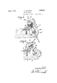
- FIG. 1 is a side elevation of a grinding machine in accordance with this invention.
- Figure 2 is a top plan view thereof.
- Figure 8 is a top plan view of the machine anchored to an engine block.
- Figure 4 is a sectional plan of the machine anchored to an engine block, the latter being shown fragmentary in plan.
- the machine includes a foot piece referred to generally at 1 and which is adapted to be adjustably connected to the engine block 2.
- the foot piece 1 includes T-shaped body formed of a longitudinally extending slotted part 3 and a horizontally disposed slotted part a which is integral with the inner side of the part 3 centrally thereof.
- the slot in the part 3 is indicated at 5 and that in the part a at 6.
- the slots 5, 6 do not communicate with each other.
- the foot piece 1 is adapted to be positioned upon the top of the engine block 2 and is adj ustably secured therewith by holdfast devices 7, 8, the former extending through the slot- 5 and the latter through the slot 6.
- the holdfast devices engage in a pair of sockets provided in the engine block for the reception of holdfast devices, not shown, for fixedly securing the engine head, not shown in position.
- the sockets or openings which receive the holdfast devices for securing the engine head to the block 2 are indicated at 9.
- the foot piece 1 is detachably and V adjustably secured to the engine block 2 by the engagement of the holdfast devices 7, 8 in a pairof aligning sockets or, openings 9.
- the holdfast devices 7, 8 may be of any suitable form but preferably consist of bolts carrying nuts on their. upper ends, the boltsbeing 1 of the threaded, non-head type.
- the foot piece 1 further includes an outwardly directed offset part 10 which is intogral with the outer side of part3 centrally thereof, and integral with the partlO is a vertically disposed post 11 having a reduced upper portion 12, which provides a shoulder, 13 s
- the machine further includes'a supporting frame consistingof a vertically disposed plate 14 provided centrally of its bottom with an outwardly directed, right angularly disposed adjustable arm 15, a bracket member extending at right angles to the plate 14, disposed centrally respect thereto and consisting of a vertical arm 17 which mergesinto top and bottom arms 18, 19 respectively.
- the plate14 and arm provides a motor carrier I r
- the top arm 18. at its ends is formed with concaved parts 20, 21 which are oppositely disposed.
- the part 20 is formed with oppo-' sitely extending flanges 221
- the part 21 is provided withoppositely extending flanges 23.
- the lower arm19' has its ends formed of concaved parts24 25 which are oppositely,
- a semicircularbearing cap 34 Positioned against the part 24 is a semicircularbearing cap 34, laterally flanged as at 35.. The flanges oppose the flanges 26. Projecting from the flanges 35 are tubular extensions 36 which abut against the inner face of the plate 14 near the bottom of the latter. Extending through plate 14, extensions 36 and flanges 35 and 26 are holdfast devices 37.
- the cap 34 coact-s with the part 24-for the passage of the post 33 and the latter is tightly clamped to the top and bottom bars 18, 19 respectively of the bracket member.
- .Holdfast devices 31 secure-flanges- 7 22, 28-together, aswellas the bracket meme driven thereby.
- r y V I The drivingpulley 55 is arranged over the her to plate 14.
- the post 33 is vertically adjustableto position the supporting frame of t hemachine at the desired height with respect to the work to be operated upon.
- Extending through the flanges 41 is'a holdfast device 44 and extending through the flanges 43 is a holdfast device 45."
- the collar '40 is mounted on the Thepost 33 isadjustably supported fromreduced zpor'tion 120i the post llandseats upon the shoulder 13.v
- the collar ,42 embraces the lower portion of the post
- the holdfast device 44 in connectionlwith the i flanges41 tightly clamps the collar 40"to the;
- Th hole
- a'sfemicircular-bearing cap 47 Positioned against the part. 21 is a'sfemicircular-bearing cap 47 provided with lflanges 4Srwhichabut flanges 23.
- the flanges .48 Positioned against the part. 21 is a'sfemicircular-bearing cap 47 provided with lflanges 4Srwhichabut flanges 23.
- the cap .47 in connection with the part 21 provides an upper bearing for adrivingspindle 50.
- a semi-circular bearing cap 51 Positioned: against-- the part 25 is a semi-circular bearing cap 51 provided with flanges 52 which abut flanges i 27 and are-fixedly secured therewith by the holdfast devices 53.
- The'cap51 inpconnecp I s;
- the upper portionof thehspindler is formed with a lengthwise extendinggroove 54 for, the reception of a key carried by a driving pulley 55 for p e-'50s
- Theglower V i 7 end of the spindle 50. is formed with a-f socket member-56 to receive the shank 57lof-ani abrading or grinding element or tool 58.
- shank 57 is detachably. connected to the men ⁇ ber 56 and by this arrangement provision is had wherebytools of different diameters can be detachably secured to the spindle50 to be top bar18 of the bracket member and the hub ofthe pulley is indicated at'59.
- the hub 53 of the pulley 55 is peripherally grooved to receive the holder member 60.
- a motor 61 preferably of the electric type, and which has its housing formed with oppositely extending, laterally disposed webs 62 or which may be a plate and said webs 62 are fixedly secured to the plate 1% by the holdfast devices 63.
- the shaft of the motor is indicated at 64 and has its lower end extend to the outer end of the arm 15.
- the shaft 6 has its upper end provided with a pulley 65 and leading therefrom is a driving belt 67 for the purpose of operating the pulley 65.
- an upstanding movable support 68 which inclines in a direction away from the spindle 50. Carried by the support 68 in proximity to its upper end is a pivot 69 upon which is pivotally mounted the arms 70 of the yoke-shaped portion 71 of an operating handle 72.
- the upper end of the driving spindle 50 is provided with a head piece 73 formed with a pair of oppositely entendiru lugs 7% which provide pivots for the arms r0 of the yoke-shaped portion 71 of the operating handle 72.
- the upper end of the support 68 carries a pin or stud 75 to which is connected the upper end of a controlling spring 76 for the operating handle 72.
- the lower end of the spring 7 6 is fixedly secured to a short rod 77 carried by the arm 70 of the yoke-shape portion 71.
- a grinding machine comprising a vertically adjustable element, a bracket provided at its outer end with superposed bearings, a motor carrier, means for clamping the carrier and the inner end of the bracket to the upper portion of said element, a foot piece, an angularly adjustable arm connected to said foot piece and supporting said element, a rotatable and vertically ad ustable spindle, spindle driving means mounted on the upper of said bearings, said spindle extend through said driving means and beain f said spindle and driving means having coacting means for rotatably and slidably connecting the spindle to said driving means, a support carried by the bracket, and spring controlled means connected with said support and with the spindle for vertically adjusting the latter.
- a grinding machine comprising a bracket having superposed bearings at its anda spring controlled means pivotally connected with said bracket and with said spindle for vertically adjusting the latter.
- a vertically adjustable post provided on its lower portion with a vertically adjustable collar, a horizontally disposed angularly adjustable arm having means at its outer end for securing the lower end of said post therein, said collar abutting the top of the outer end of said arm, supporting means for said arm, said arm having means at its inner end for clamping it to said supporting means, a supporting structure clamped intermediate its ends to the upper portion of said post, and a spindle and spindle driving mechanism carried by said supporting structure.
- avertically adjustable post provided on its lower portion with a vertically adjustable collar, a horizontally disposed angularly adjustable arm having means at its outer endfor securing the lower end of said post therein, said collar abutting the top of the outer end of said arm, supporting'means for said arm, said arm hav ing means at its inner end for clamping it to said supporting means, a supporting structure clamped intermediate its ends to the upper portion of said post, and a spindle and spindle driving mechanism carried by said supporting structure, said supporting structure including superposed bearings for the spindle and a motor carrier.
- a vertically adjustable post provided on its lower portion with a vertically adjustable collar, a horizontally disposed angularly adjustable arm having means at its outer end for securing the lower end of said post therein, said collar abutting the top of the outer end of said arm, supporting means for said arm, said arm having means at its inner end for clamping it to said supporting means, a supporting structure clamped intermediate its ends at the upper portion of said post, a spindle and spindle driving mechanism carried by said supporting structure, said spindle being vertically adjustable, and a spring controlled means pivotally connected with said supporting structure and with said spindle for vertically adjusting the latter.
- a verticallyad justable post provided on its lower portion with a vertically adjustable collar, a horizontally disposed angularly adjustable arm 5 having meansat its outer end for securing the lower end'of said post therein, said collar abutting the top of the outer end of said arm, supporting means for said arm, said arm having means at its inner end for clamplo ing it to said supporting means, a supporting structure clamped intermediate its ends to the upper portion of said post, a spindle and spindle driving-mechanism carried by said supportingstructure, said supporting structure including superposed bearings for the spindle anda motor carrier, said spindle being vertically adjustable, and-springcontrolled “means pivotally connected with said supporting structure and with said-spindle for vertically adjusting the latter.
- a'verti'cally adjustable post provided on its lower portion with'avertically adjustable collar, a horizontally-disposed angularly adjustable arm having means at its outer end for clamping the lower end of said post thereto, said collar for abutting the topof the outer end of said arm wherethepostisclamped to the latter, a support for said :arm, said arm'having jmeans at its other end for clamping it to said support, a tool spindle, a bracket having superposed bearings for said spindle, a motor carrier, means 'for'clamping the bracket and carrier to the upper portionof said post, and driving mechanism for said spindle arranged abovesaidbracket and carrier.
Landscapes
- Engineering & Computer Science (AREA)
- Mechanical Engineering (AREA)
- Grinding And Polishing Of Tertiary Curved Surfaces And Surfaces With Complex Shapes (AREA)
Description
May 3, 1932- G. ENOCHSON 1,357,047
GRINDING MACHINE Filed Sept. 50, 1929 2 Sheets-Sheet l Eilll IN VEN TOR.
G E 71 B u no son y 19320 G. ENOCHSON 1,857,047
GRINDING MACHINE Filed Sept. 30, 1929 2 Sheets-Sheet 2 INVENTOR.
' ATTORNEY.
Cir
Patented May 3, 1932 UNITED STATES PTENT OFFICE GUY ENOCI-ISON, 0F AUSTIN, MINNESOTA GRINDING- MACHINE This invention relates to a grinding machine designed primarily for grinding the walls of cylinders of internal combustion engines, but it is to be understood that a ma- 1 chine, in accordance with this invention may be employed for grinding valve seats or for any other purposes for which it is found applicable, and the invention has for its object to provide, in a manner as hereinafter set forth, a machine of the class referred to including means for anchoring it to an engine block and further including means for adjustably positioning the abrading or grinding element thereof for action upon the wall of any one of the cylinders of the block witl out disconnecting the machine from the latter.
A further object of the invention is to provide, in a manner as hereinafter referred to, a machine of the class referred to including a supporting frame and means to enable the vertical and angular adjustment of the frame when occasion requires to position the driving spindle thereof at the desired point with respect to the object which is to be ground.
A further object of the invention is to provide, in a manner as hereinafter set forth, a machine of the class referred to including means for anchoring it to an engine block and further including means to permit of the abra'ding or grinding element of the machine acting upon all of the cylinder walls of the block without disconnecting the machine from the latter.
A further object of the invention is to provide, in a manner as hereinafter set forth, a machine of the class referred to including a verticaly adjustable, spring controlled driving spindle for the abrading or grinding element of the machine whereby the lowering of the latter is had against the action of the controlling spring for the spindle and fur ther whereby the abrading element can be quickly removed when not active with respect to the cylinder wall.
Further objects of the invent-ion are to provide, in a manner as hereinafter set forth, a grinding machine for the purpose referred to which is simple in its construction, strong, durable, portable, thoroughly eflicient in its use, conveniently adjusted, quickly anchored in stationary position when desired to be used, readily assembled, and comparatively inexpensive to set up and designed to be used for driving any type of cylinder hone for grinding purposes.
l Vith the foregoing and other objects in view the invention consists of the novel construction, combination and arrangement of parts as hereinafter more specifically described, and illustrated in the accompanying drawings, wherein is shown an embodiment of the invention, but it is to be understood that changes, variations and modifications canbe resorted to which fall within the scope of the claims hereunto appended.
In the drawings wherein like reference characters denote corresponding parts throughout the several views Figure 1 is a side elevation of a grinding machine in accordance with this invention.
Figure 2 is a top plan view thereof.
Figure 8 is a top plan view of the machine anchored to an engine block.
Figure 4 is a sectional plan of the machine anchored to an engine block, the latter being shown fragmentary in plan.
The machine includes a foot piece referred to generally at 1 and which is adapted to be adjustably connected to the engine block 2. The foot piece 1 includes T-shaped body formed of a longitudinally extending slotted part 3 and a horizontally disposed slotted part a which is integral with the inner side of the part 3 centrally thereof. The slot in the part 3 is indicated at 5 and that in the part a at 6. The slots 5, 6 do not communicate with each other. The foot piece 1 is adapted to be positioned upon the top of the engine block 2 and is adj ustably secured therewith by holdfast devices 7, 8, the former extending through the slot- 5 and the latter through the slot 6. The holdfast devices engage in a pair of sockets provided in the engine block for the reception of holdfast devices, not shown, for fixedly securing the engine head, not shown in position. The sockets or openings which receive the holdfast devices for securing the engine head to the block 2 are indicated at 9. As shown in Figure 4 the foot piece 1 is detachably and V adjustably secured to the engine block 2 by the engagement of the holdfast devices 7, 8 in a pairof aligning sockets or, openings 9. The holdfast devices 7, 8 may be of any suitable form but preferably consist of bolts carrying nuts on their. upper ends, the boltsbeing 1 of the threaded, non-head type.
The foot piece 1 further includes an outwardly directed offset part 10 which is intogral with the outer side of part3 centrally thereof, and integral with the partlO is a vertically disposed post 11 having a reduced upper portion 12, which provides a shoulder, 13 s The machine further includes'a supporting frame consistingof a vertically disposed plate 14 provided centrally of its bottom with an outwardly directed, right angularly disposed adjustable arm 15, a bracket member extending at right angles to the plate 14, disposed centrally respect thereto and consisting of a vertical arm 17 which mergesinto top and bottom arms 18, 19 respectively. I H
"The plate14 and arm provides a motor carrier I r The top arm 18. at its ends is formed with concaved parts 20, 21 which are oppositely disposed. The part 20 is formed with oppo-' sitely extending flanges 221 The part 21 is provided withoppositely extending flanges 23. The lower arm19' has its ends formed of concaved parts24 25 which are oppositely,
disposed. Projecting from the part 24 are oppositely extending flanges 26, and proj ecting from the P2111125 are oppositely extending flanges 27. The outer portion of thearm 19, a
acts with the part 20 to receive a vertically disposed post 33. Y
. Positioned against the part 24 is a semicircularbearing cap 34, laterally flanged as at 35.. The flanges oppose the flanges 26. Projecting from the flanges 35 are tubular extensions 36 which abut against the inner face of the plate 14 near the bottom of the latter. Extending through plate 14, extensions 36 and flanges 35 and 26 are holdfast devices 37. The cap 34 coact-s with the part 24-for the passage of the post 33 and the latter is tightly clamped to the top and bottom bars 18, 19 respectively of the bracket member. .Holdfast devices 31 secure-flanges- 7 22, 28-together, aswellas the bracket meme driven thereby. r y V I The drivingpulley 55 is arranged over the her to plate 14. The holdfast devices 31, 37
act to clamp the bracket member to the post 33. The post 33 is vertically adjustableto position the supporting frame of t hemachine at the desired height with respect to the work to be operated upon.
the postll'by an arm 39 provided at one end with a split collar 40 formed with a pair of flanges 41 and at its other end with a split collar '42 provided with a pair of flanges 43. Extending through the flanges 41 is'a holdfast device 44 and extending through the flanges 43 is a holdfast device 45." The collar '40 is mounted on the Thepost 33 isadjustably supported fromreduced zpor'tion 120i the post llandseats upon the shoulder 13.v The collar ,42 embraces the lower portion of the post The holdfast device 44 in connectionlwith the i flanges41 tightly clamps the collar 40"to the;
reduced portion 12 of ost 11'. Th hole:
fast devices'45 inconnection .Withthe flanges i 43 tightly clamp the collar 42 to thelower;
por ion of the post-33.; r 1 g Carried by the post33 is an adjusta'blestop "ac collar 46 which seatsupon thetopof collar .42. The adjustment ofcollar flfl 'rel ative to post provides for the positioningof the supporting frame ofthewmachine ,atethe de} sired point. 7 Furtherjwhen the V collar; 40" is releasedv from bindingengagement; with the reduced portion12 of the post 11 theme 39 can be swung at any desirable inclination" l with respect to post 11 to position thesup porting frame at an angle with respect to the latter.
p V Positioned against the part. 21 is a'sfemicircular-bearing cap 47 provided with lflanges 4Srwhichabut flanges 23. The flanges .48
are secured to the flanges '23 by the'hold-t] 7 fast devices '49. The cap .47 in connection with the part 21provides an upper bearing for adrivingspindle 50. Positioned: against-- the part 25 is a semi-circular bearing cap 51 provided with flanges 52 which abut flanges i 27 and are-fixedly secured therewith by the holdfast devices 53. The'cap51 inpconnecp I s;
a lower heap tlQIl' with the part 25 provides ing for thedriving spindle 50.
The upper portionof thehspindler is formed witha lengthwise extendinggroove 54 for, the reception of a key carried by a driving pulley 55 for p e-'50s Theglower V i 7 end of the spindle 50. is formed with a-f socket member-56 to receive the shank 57lof-ani abrading or grinding element or tool 58. The
Opposing the plate 14, is a motor 61 preferably of the electric type, and which has its housing formed with oppositely extending, laterally disposed webs 62 or which may be a plate and said webs 62 are fixedly secured to the plate 1% by the holdfast devices 63. The shaft of the motor is indicated at 64 and has its lower end extend to the outer end of the arm 15. The shaft 6 has its upper end provided with a pulley 65 and leading therefrom is a driving belt 67 for the purpose of operating the pulley 65.
Secured to the top bar 18 of the bracket member is an upstanding movable support 68 which inclines in a direction away from the spindle 50. Carried by the support 68 in proximity to its upper end is a pivot 69 upon which is pivotally mounted the arms 70 of the yoke-shaped portion 71 of an operating handle 72. The upper end of the driving spindle 50 is provided with a head piece 73 formed with a pair of oppositely entendiru lugs 7% which provide pivots for the arms r0 of the yoke-shaped portion 71 of the operating handle 72.
The upper end of the support 68 carries a pin or stud 75 to which is connected the upper end of a controlling spring 76 for the operating handle 72. The lower end of the spring 7 6 is fixedly secured to a short rod 77 carried by the arm 70 of the yoke-shape portion 71.
It is thought the many advantages or" a grinding machine, in accordance with tiis invention can be readily understood, and although the preferred embodiment of the in vention is as illustrated and described, yet it is to be understood that changes in the details of construction can be had which fall within the scope of the invention as claimed.
What I claim is 1. A grinding machine comprising a vertically adjustable element, a bracket provided at its outer end with superposed bearings, a motor carrier, means for clamping the carrier and the inner end of the bracket to the upper portion of said element, a foot piece, an angularly adjustable arm connected to said foot piece and supporting said element, a rotatable and vertically ad ustable spindle, spindle driving means mounted on the upper of said bearings, said spindle extend through said driving means and beain f said spindle and driving means having coacting means for rotatably and slidably connecting the spindle to said driving means, a support carried by the bracket, and spring controlled means connected with said support and with the spindle for vertically adjusting the latter.
2. A grinding machine comprising a bracket having superposed bearings at its anda spring controlled means pivotally connected with said bracket and with said spindle for vertically adjusting the latter.
3. in a grinding machine, a vertically adjustable post provided on its lower portion with a vertically adjustable collar, a horizontally disposed angularly adjustable arm having means at its outer end for securing the lower end of said post therein, said collar abutting the top of the outer end of said arm, supporting means for said arm, said arm having means at its inner end for clamping it to said supporting means, a supporting structure clamped intermediate its ends to the upper portion of said post, and a spindle and spindle driving mechanism carried by said supporting structure.
st. in a grinding machine, avertically adjustable post provided on its lower portion with a vertically adjustable collar, a horizontally disposed angularly adjustable arm having means at its outer endfor securing the lower end of said post therein, said collar abutting the top of the outer end of said arm, supporting'means for said arm, said arm hav ing means at its inner end for clamping it to said supporting means, a supporting structure clamped intermediate its ends to the upper portion of said post, and a spindle and spindle driving mechanism carried by said supporting structure, said supporting structure including superposed bearings for the spindle and a motor carrier.
5. In a grinding machine, a vertically adjustable post provided on its lower portion with a vertically adjustable collar, a horizontally disposed angularly adjustable arm having means at its outer end for securing the lower end of said post therein, said collar abutting the top of the outer end of said arm, supporting means for said arm, said arm having means at its inner end for clamping it to said supporting means, a supporting structure clamped intermediate its ends at the upper portion of said post, a spindle and spindle driving mechanism carried by said supporting structure, said spindle being vertically adjustable, and a spring controlled means pivotally connected with said supporting structure and with said spindle for vertically adjusting the latter.
- 6. In a grinding machine,"a verticallyad justable post provided on its lower portion with a vertically adjustable collar, a horizontally disposed angularly adjustable arm 5 having meansat its outer end for securing the lower end'of said post therein, said collar abutting the top of the outer end of said arm, supporting means for said arm, said arm having means at its inner end for clamplo ing it to said supporting means, a supporting structure clamped intermediate its ends to the upper portion of said post, a spindle and spindle driving-mechanism carried by said supportingstructure, said supporting structure including superposed bearings for the spindle anda motor carrier, said spindle being vertically adjustable, and-springcontrolled "means pivotally connected with said supporting structure and with said-spindle for vertically adjusting the latter.
In aigrinding machine, a'verti'cally adjustable post provided on its lower portion with'avertically adjustable collar, a horizontally-disposed angularly adjustable arm having means at its outer end for clamping the lower end of said post thereto, said collar for abutting the topof the outer end of said arm wherethepostisclamped to the latter, a support for said :arm, said arm'having jmeans at its other end for clamping it to said support, a tool spindle, a bracket having superposed bearings for said spindle, a motor carrier, means 'for'clamping the bracket and carrier to the upper portionof said post, and driving mechanism for said spindle arranged abovesaidbracket and carrier. 8. Ina grinding machine, a vertically adjustable post-provided on its lower portion with a vertically adjustable'collar, ahori "40 zontally disposed angularly'adjustable arm having means at its outer end for clamping the lower end of said post thereto, said collar for abutting the top of the outer end of said arm where the post :is'clamped to the latter, a :support for said arm, said arm having means .at'its.v other end for clamping it to said support, a tool spindle, a bracket having superposed bearings for said spindle, a motor carrier, means for clamping the bracket and carrier to the upper portion of said post, driving mechanism for said spindle arranged above said bracket and carrier,'sai'd spindle beingvertically adjustable, and means pivotally connected with said bracket and with said spindle for vertically adjusting the latter. I r s Intestimony whereof,-I afiix my signature hereto; w V r a GUY ENOCHSON.
Priority Applications (1)
| Application Number | Priority Date | Filing Date | Title |
|---|---|---|---|
| US396293A US1857047A (en) | 1929-09-30 | 1929-09-30 | Grinding machine |
Applications Claiming Priority (1)
| Application Number | Priority Date | Filing Date | Title |
|---|---|---|---|
| US396293A US1857047A (en) | 1929-09-30 | 1929-09-30 | Grinding machine |
Publications (1)
| Publication Number | Publication Date |
|---|---|
| US1857047A true US1857047A (en) | 1932-05-03 |
Family
ID=23566644
Family Applications (1)
| Application Number | Title | Priority Date | Filing Date |
|---|---|---|---|
| US396293A Expired - Lifetime US1857047A (en) | 1929-09-30 | 1929-09-30 | Grinding machine |
Country Status (1)
| Country | Link |
|---|---|
| US (1) | US1857047A (en) |
Cited By (2)
| Publication number | Priority date | Publication date | Assignee | Title |
|---|---|---|---|---|
| US2520676A (en) * | 1945-05-25 | 1950-08-29 | Arthur P Dredske | Surface grinder attachment for milling machines |
| US2655771A (en) * | 1950-02-06 | 1953-10-20 | Micromatic Hone Corp | Honing tool for external cylindrical surfaces |
-
1929
- 1929-09-30 US US396293A patent/US1857047A/en not_active Expired - Lifetime
Cited By (2)
| Publication number | Priority date | Publication date | Assignee | Title |
|---|---|---|---|---|
| US2520676A (en) * | 1945-05-25 | 1950-08-29 | Arthur P Dredske | Surface grinder attachment for milling machines |
| US2655771A (en) * | 1950-02-06 | 1953-10-20 | Micromatic Hone Corp | Honing tool for external cylindrical surfaces |
Similar Documents
| Publication | Publication Date | Title |
|---|---|---|
| US2291999A (en) | Tool holder | |
| CN108838760A (en) | Crankshaft grinding machine grinding wheel adjusts device | |
| US1857047A (en) | Grinding machine | |
| US2612007A (en) | Abrasive belt attachment for abrasive wheel machines | |
| US1877705A (en) | Scroll saw | |
| US3574268A (en) | Tool sharpening apparatus | |
| US526571A (en) | Henry j | |
| US3225492A (en) | Lapping apparatus | |
| US2359704A (en) | Forming guide for engraving machines | |
| US3648416A (en) | Portable valve facer | |
| CN112372083B (en) | Opposite grinding operation device and opposite grinding equipment thereof | |
| US1852193A (en) | Jig saw | |
| US6298573B1 (en) | Centering device for a saw blade | |
| CN210476589U (en) | A grinding fixture supported by the outer ring of a bearing | |
| US1923416A (en) | Armature turning and undercutting lathe | |
| CN103433557B (en) | A kind of automatic gear grinding device of band saw sawtooth | |
| US2189015A (en) | Grinder | |
| US1845069A (en) | Tool supporting and operating fixture | |
| CN208663172U (en) | Clamping tool is used in a kind of processing of bearing block | |
| US662793A (en) | Mower-knife grinder. | |
| US2471208A (en) | Portable drill brace | |
| GB664236A (en) | Improvements in or relating to a rotary tool supporting assembly | |
| CN216179256U (en) | Fixed pipe support inner wall grinding device | |
| US537411A (en) | Machine for concaving razors | |
| US2260158A (en) | Machine for boring bearing shells |