US1857045A - Packing - Google Patents
Packing Download PDFInfo
- Publication number
- US1857045A US1857045A US291643A US29164328A US1857045A US 1857045 A US1857045 A US 1857045A US 291643 A US291643 A US 291643A US 29164328 A US29164328 A US 29164328A US 1857045 A US1857045 A US 1857045A
- Authority
- US
- United States
- Prior art keywords
- packing
- rings
- shaft
- housing
- ring
- Prior art date
- Legal status (The legal status is an assumption and is not a legal conclusion. Google has not performed a legal analysis and makes no representation as to the accuracy of the status listed.)
- Expired - Lifetime
Links
- 238000012856 packing Methods 0.000 title description 31
- 210000004907 gland Anatomy 0.000 description 7
- 239000000314 lubricant Substances 0.000 description 2
- OKTJSMMVPCPJKN-UHFFFAOYSA-N Carbon Chemical compound [C] OKTJSMMVPCPJKN-UHFFFAOYSA-N 0.000 description 1
- 230000006835 compression Effects 0.000 description 1
- 238000007906 compression Methods 0.000 description 1
- 238000010276 construction Methods 0.000 description 1
- NRUQNUIWEUZVLI-UHFFFAOYSA-O diethanolammonium nitrate Chemical compound [O-][N+]([O-])=O.OCC[NH2+]CCO NRUQNUIWEUZVLI-UHFFFAOYSA-O 0.000 description 1
- 239000002657 fibrous material Substances 0.000 description 1
- 239000012530 fluid Substances 0.000 description 1
- 239000007789 gas Substances 0.000 description 1
- 229910002804 graphite Inorganic materials 0.000 description 1
- 239000010439 graphite Substances 0.000 description 1
- VKYKSIONXSXAKP-UHFFFAOYSA-N hexamethylenetetramine Chemical compound C1N(C2)CN3CN1CN2C3 VKYKSIONXSXAKP-UHFFFAOYSA-N 0.000 description 1
- 230000001050 lubricating effect Effects 0.000 description 1
- 238000003825 pressing Methods 0.000 description 1
- 239000012858 resilient material Substances 0.000 description 1
- 238000007789 sealing Methods 0.000 description 1
- 239000000126 substance Substances 0.000 description 1
- 239000003760 tallow Substances 0.000 description 1
Images
Classifications
-
- F—MECHANICAL ENGINEERING; LIGHTING; HEATING; WEAPONS; BLASTING
- F16—ENGINEERING ELEMENTS AND UNITS; GENERAL MEASURES FOR PRODUCING AND MAINTAINING EFFECTIVE FUNCTIONING OF MACHINES OR INSTALLATIONS; THERMAL INSULATION IN GENERAL
- F16J—PISTONS; CYLINDERS; SEALINGS
- F16J15/00—Sealings
- F16J15/16—Sealings between relatively-moving surfaces
- F16J15/18—Sealings between relatively-moving surfaces with stuffing-boxes for elastic or plastic packings
- F16J15/20—Packing materials therefor
Definitions
- This invention relates to improvements in packing glands.
- a packing gland which is simple in structure and durable, and adapted for either a reciprocating shaft or rotary shaft in any type of machineor device whereby gases or fluids are handled and packing glands are necessary.
- the packing gland is self adjusting for alignment of a shaft.
- a still further object is that the metallic parts of the packing are not subject to any appreciable wear with rotation or reciprocation of the associated shaft.
- Figure 1 is a sectional view of a packing embodying the present invention
- Figure 2 is an enlarged transverse section of a packing unit of this invention.
- Figure 3 is an outer end view partly in elevation and partly in section, the latter illustrating the segmental rings of the packing.
- the hub or housing 11 may be fitted about the shaft 10 as at 12 and the interior of the housing is enlarged as at 13 to provide an annular opening for the reception of the pacln'ng.
- the packing preferably comprises a plurality of packing gland units as shown to advantage in Figure 1.
- Each packing unit comprises two rings 14 and 15, complemental in structure and adapted to provide an annular groove 16, when arranged in assembled relation.
- the rings 14 and '15 are preferably segmental as shown with a dowel pin 17 that may engage in a suitable opening 18 in an opposing ring of anadjacent packing unit.
- This backing ring is designated by the reference numeral 19 and is preferably of rubber of heat resisting quality or characteror other substance having suitable resiliency and heat resistance.
- the backing ring 19 is so shaped that its sides 20 conform to the curvature of the inner sides of the rings 14 and 15'formin g grooves 16. However, the ring 19 is of such thickness that normally the inner edges of the rings 14 and 15 of each packing unit are spaced as shown at 21.
- Each backing ring 19 is provided with a groove 22 upon its inner periphery in "which there is placed a lubricating rope or cord preferably constituting a plurality of I strands 23 of fibrous material impregnated with tallow, graphite, or other suitable lubricant.
- the backing ring 19 isl formed' with protrusions or extensions 23a about its outer periphery, that are adapted toseat'uponi the outer peripheries of the associated rings l415.
- each'of the rings 14-15 has its outer side provided with an offset 24 about its inner periphery. The offsets provide grooves 25 when the packing units are arranged'in assembled relation.
- the hub or housing 11 is provided at its outer end with openings 26.
- a gland fol-f lower 2'? is provided having an annular flange 28.
- the flange 28 carries machine bolts 29 threaded into the openings 26 of the housing 11 and serve to force the follower 27 into the housing 11 as illustrated to advantage in Figure 1.
- offsets 24 in the rings 14-15 in conjunction with the spaces 21, form alabyrinth packing in addition to the sealing of rings 19 and rings 1415; r r
- a packing within the housing comprising a plurality of packing units, each unit including a pair of metallic-rings adapted to form an annular groove between the opposing sides thereof, a ring of resilient material within each groove and extending outwardly there from to fit within the packing housing and hold the associated pair of rings spaced from each other, eachof said rings having a planiform face for abutting relation with the planiform face of the next ring of the adj acent unit, said rings further having their outer edges formed with an offset about its inner periphery, said resilient rings having an annular groove upon their inner periphery, a compressible lubricant means in said grooves, and means for applying pressure against the sides of. said metallic rings for compression of said resilient rings.
Landscapes
- Engineering & Computer Science (AREA)
- General Engineering & Computer Science (AREA)
- Mechanical Engineering (AREA)
- Sealing Devices (AREA)
Description
W. T. DEAN May 3, 1932.
PACKING Filed July 10. 1928 Patented May 3, 1932 UNITED STATES PATENTOFFICE' WILLIAM T. DEAN, OF BEAUMONT, TEXAS, ASSIGNOR TO SWITZER I PAGKING OOMPANY,
OF BEAUMONT, TEXAS, A CORPORATION OF TEXAS PACKING Application filed July 10,1928. Serial No. 291,643.
This invention relates to improvements in packing glands.
Among the objects of the invention is to provide a packing gland which is simple in structure and durable, and adapted for either a reciprocating shaft or rotary shaft in any type of machineor device whereby gases or fluids are handled and packing glands are necessary.
It is also a purpose of the invention to provide a packing of the above character that may be easily assembled and applied to a shaft and easily adjusted for wear.
It is a further and important object of the invention that the packing gland is self adjusting for alignment of a shaft.
A still further object is that the metallic parts of the packing are not subject to any appreciable wear with rotation or reciprocation of the associated shaft.
Other objects, and objects relating to details of construction, combination and arrangement of parts will hereafter appear in the detail description to follow.
The invention is illustrated by way of example in the accompanying drawings, in which,
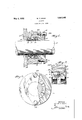
Figure 1 is a sectional view of a packing embodying the present invention,
Figure 2 is an enlarged transverse section of a packing unit of this invention, and
Figure 3 is an outer end view partly in elevation and partly in section, the latter illustrating the segmental rings of the packing.
Referring to the drawings more partic ularly, indicates a shaft and 11 a hub or packing housing. The hub or housing 11 may be fitted about the shaft 10 as at 12 and the interior of the housing is enlarged as at 13 to provide an annular opening for the reception of the pacln'ng. The packing preferably comprises a plurality of packing gland units as shown to advantage in Figure 1. Each packing unit comprises two rings 14 and 15, complemental in structure and adapted to provide an annular groove 16, when arranged in assembled relation. The rings 14 and '15 are preferably segmental as shown with a dowel pin 17 that may engage in a suitable opening 18 in an opposing ring of anadjacent packing unit.
VVithin the groove 16' formed by rings 14 and of each packing unit is placed what may be termed a backing ring. This backing ring is designated by the reference numeral 19 and is preferably of rubber of heat resisting quality or characteror other substance having suitable resiliency and heat resistance. The backing ring 19 is so shaped that its sides 20 conform to the curvature of the inner sides of the rings 14 and 15'formin g grooves 16. However, the ring 19 is of such thickness that normally the inner edges of the rings 14 and 15 of each packing unit are spaced as shown at 21.
Each backing ring 19 is provided with a groove 22 upon its inner periphery in "which there is placed a lubricating rope or cord preferably constituting a plurality of I strands 23 of fibrous material impregnated with tallow, graphite, or other suitable lubricant. l
'As best shown in Figure 2, the backing ring 19 isl formed' with protrusions or extensions 23a about its outer periphery, that are adapted toseat'uponi the outer peripheries of the associated rings l415. It will also be noted that each'of the rings 14-15 has its outer side provided with an offset 24 about its inner periphery. The offsets provide grooves 25 when the packing units are arranged'in assembled relation. It should be further noted that the dowel pins l7enable the'rings- 1415 of the packing units to beheld so that the place of joinder ofthe different sections constituting a ring are offset from those of an adjacent ring.
The hub or housing 11is provided at its outer end with openings 26. A gland fol-f lower 2'? is provided having an annular flange 28. The flange 28 carries machine bolts 29 threaded into the openings 26 of the housing 11 and serve to force the follower 27 into the housing 11 as illustrated to advantage in Figure 1.
It is thought from the foregoing description, a clear understanding of the structure and assembly of the different parts and units constituting the packing of this invention can be had. With the segmental rings 14-15 and the resilient backing rings 19, the pack ing units'as a whole forms a flexible form of packing gland. As seen in Figure ,8, the segments forming the rings 14.-15 are slightly spaced from each otherand permit take-up for wear. By bringing pressure upon the packing units through the follower 27, the rings 19 are compressed and the tight ness of the packing increased. l Also, it is pointed out that the backing rings 19 essen tially serve as seats for the rings 1415 and 7 thus enable these rings to arrange themselves to suit the alignment of the shaft 10. Due to the rings 19,.the rings 14-15 cannot serve as bearings for'shaft 10. o
It is also to be noted that the offsets 24: in the rings 14-15 in conjunction with the spaces 21, form alabyrinth packing in addition to the sealing of rings 19 and rings 1415; r r
' 7 While I have described and shown a particular application of my invention, it is to be understood that the invention is not to be so limited as indicated by the appended'cla-im.
Iclaim: v
In a rod packing, a shaft and housing, a packing within the housing comprising a plurality of packing units, each unit including a pair of metallic-rings adapted to form an annular groove between the opposing sides thereof, a ring of resilient material within each groove and extending outwardly there from to fit within the packing housing and hold the associated pair of rings spaced from each other, eachof said rings having a planiform face for abutting relation with the planiform face of the next ring of the adj acent unit, said rings further having their outer edges formed with an offset about its inner periphery, said resilient rings having an annular groove upon their inner periphery, a compressible lubricant means in said grooves, and means for applying pressure against the sides of. said metallic rings for compression of said resilient rings.
Signed at Beaumont, in the county of Jeffferson and State of Texas, this 18th day of October, A. D.i1927.
:WILLIAM T. DEAN.
Priority Applications (1)
| Application Number | Priority Date | Filing Date | Title |
|---|---|---|---|
| US291643A US1857045A (en) | 1928-07-10 | 1928-07-10 | Packing |
Applications Claiming Priority (1)
| Application Number | Priority Date | Filing Date | Title |
|---|---|---|---|
| US291643A US1857045A (en) | 1928-07-10 | 1928-07-10 | Packing |
Publications (1)
| Publication Number | Publication Date |
|---|---|
| US1857045A true US1857045A (en) | 1932-05-03 |
Family
ID=23121164
Family Applications (1)
| Application Number | Title | Priority Date | Filing Date |
|---|---|---|---|
| US291643A Expired - Lifetime US1857045A (en) | 1928-07-10 | 1928-07-10 | Packing |
Country Status (1)
| Country | Link |
|---|---|
| US (1) | US1857045A (en) |
Cited By (1)
| Publication number | Priority date | Publication date | Assignee | Title |
|---|---|---|---|---|
| US4111435A (en) * | 1973-11-14 | 1978-09-05 | Entreprise D'equipements Mecaniques Et Hydrauliques Emh | Fluid-tight sealing devices |
-
1928
- 1928-07-10 US US291643A patent/US1857045A/en not_active Expired - Lifetime
Cited By (1)
| Publication number | Priority date | Publication date | Assignee | Title |
|---|---|---|---|---|
| US4111435A (en) * | 1973-11-14 | 1978-09-05 | Entreprise D'equipements Mecaniques Et Hydrauliques Emh | Fluid-tight sealing devices |
Similar Documents
| Publication | Publication Date | Title |
|---|---|---|
| US2247505A (en) | Seal | |
| US2981573A (en) | Bearings of plastics | |
| US2394364A (en) | Pressure seal | |
| US2199735A (en) | Packing gland | |
| US2368380A (en) | Shaft seal | |
| US3183009A (en) | Grooved packing cup | |
| US2442687A (en) | Packing for stuffing boxes | |
| US2210823A (en) | Laterally expanded oil seal | |
| US1857045A (en) | Packing | |
| US926841A (en) | Packing for stuffing-boxes. | |
| US2968516A (en) | Packing rings for use on double acting pistons | |
| US2202770A (en) | Seal for enclosed bearings | |
| US2045026A (en) | Bearing and oiling system therefor | |
| US917690A (en) | Packing for stuffing-boxes. | |
| US2277771A (en) | Oil seal ring for propeller shaft lubrication | |
| US3070377A (en) | Sealing arrangement between relatively rotating parts in hydraulic and pneumatic motors, internal combustion engines and the like | |
| US601614A (en) | John w | |
| US1788966A (en) | Automatically-adjustable seal packing | |
| US2856209A (en) | Packing for rotary element or shaft | |
| US2006902A (en) | Packing ring | |
| US1617952A (en) | Rod packing | |
| US1842942A (en) | Metallic packing for reciprocating or rotating members | |
| US1089789A (en) | Piston-rod packing. | |
| US503723A (en) | Charles longstreth | |
| US661384A (en) | Metallic packing. |