US1857043A - Circuit controller - Google Patents
Circuit controller Download PDFInfo
- Publication number
- US1857043A US1857043A US252257A US25225728A US1857043A US 1857043 A US1857043 A US 1857043A US 252257 A US252257 A US 252257A US 25225728 A US25225728 A US 25225728A US 1857043 A US1857043 A US 1857043A
- Authority
- US
- United States
- Prior art keywords
- rod
- lever
- circuit
- button
- lighting
- Prior art date
- Legal status (The legal status is an assumption and is not a legal conclusion. Google has not performed a legal analysis and makes no representation as to the accuracy of the status listed.)
- Expired - Lifetime
Links
- 230000011664 signaling Effects 0.000 description 33
- 230000000994 depressogenic effect Effects 0.000 description 9
- 210000003811 finger Anatomy 0.000 description 9
- 210000003813 thumb Anatomy 0.000 description 4
- 230000013707 sensory perception of sound Effects 0.000 description 3
- 238000010276 construction Methods 0.000 description 2
- 230000000881 depressing effect Effects 0.000 description 2
- 210000005069 ears Anatomy 0.000 description 2
- 230000000694 effects Effects 0.000 description 2
- 208000036366 Sensation of pressure Diseases 0.000 description 1
- 238000010586 diagram Methods 0.000 description 1
- 230000006870 function Effects 0.000 description 1
- 238000009413 insulation Methods 0.000 description 1
- 238000012856 packing Methods 0.000 description 1
- 230000000452 restraining effect Effects 0.000 description 1
- 238000004904 shortening Methods 0.000 description 1
Images

Classifications
-
- B—PERFORMING OPERATIONS; TRANSPORTING
- B60—VEHICLES IN GENERAL
- B60Q—ARRANGEMENT OF SIGNALLING OR LIGHTING DEVICES, THE MOUNTING OR SUPPORTING THEREOF OR CIRCUITS THEREFOR, FOR VEHICLES IN GENERAL
- B60Q1/00—Arrangement of optical signalling or lighting devices, the mounting or supporting thereof or circuits therefor
- B60Q1/02—Arrangement of optical signalling or lighting devices, the mounting or supporting thereof or circuits therefor the devices being primarily intended to illuminate the way ahead or to illuminate other areas of way or environments
- B60Q1/04—Arrangement of optical signalling or lighting devices, the mounting or supporting thereof or circuits therefor the devices being primarily intended to illuminate the way ahead or to illuminate other areas of way or environments the devices being headlights
- B60Q1/14—Arrangement of optical signalling or lighting devices, the mounting or supporting thereof or circuits therefor the devices being primarily intended to illuminate the way ahead or to illuminate other areas of way or environments the devices being headlights having dimming means
- B60Q1/1446—Arrangement of optical signalling or lighting devices, the mounting or supporting thereof or circuits therefor the devices being primarily intended to illuminate the way ahead or to illuminate other areas of way or environments the devices being headlights having dimming means controlled by mechanically actuated switches
- B60Q1/1453—Hand actuated switches
- B60Q1/1461—Multifunction switches for dimming headlights and controlling additional devices, e.g. for controlling direction indicating lights
- B60Q1/1484—Multifunction switches for dimming headlights and controlling additional devices, e.g. for controlling direction indicating lights mounted on the steering wheel
-
- Y—GENERAL TAGGING OF NEW TECHNOLOGICAL DEVELOPMENTS; GENERAL TAGGING OF CROSS-SECTIONAL TECHNOLOGIES SPANNING OVER SEVERAL SECTIONS OF THE IPC; TECHNICAL SUBJECTS COVERED BY FORMER USPC CROSS-REFERENCE ART COLLECTIONS [XRACs] AND DIGESTS
- Y10—TECHNICAL SUBJECTS COVERED BY FORMER USPC
- Y10T—TECHNICAL SUBJECTS COVERED BY FORMER US CLASSIFICATION
- Y10T74/00—Machine element or mechanism
- Y10T74/20—Control lever and linkage systems
- Y10T74/20207—Multiple controlling elements for single controlled element
- Y10T74/20256—Steering and controls assemblies
- Y10T74/20262—Rotary control shaft
Definitions
- My invention relates to a circuit controller for automotive vehicles and particularly to a control of the lighting and horn or signaling circuits thereof and has for its general object the provision of an improved interrelation of the lighting circuit lever and the signaling circuit push button whereby accessibility to said lever is facilitated and increased and the obtrusiveness of the lever is reducible to a minimum.
- a lighting lever was disposed above the hand operated steering wheel and a horn or signaling circuit controlling push button was surrounded by the hub of the lever, a construction which necessitated the enlargement of the handle hub and the projection of the lever handle suhiciently upon one side of the lever axis to enable it to be effectively grasped.
- I surround the entire lighting lever by the push button, the top of the lever being sufficiently close to the top of the button as to enable the button to be depressed without interference from the lever.
- the button is desirably provided with an annular recess at its top in which the gripping portion of the lighting lever is preferably received.
- the axis of the lever is central with respect to tne gripping por- 33 tion of the lever, this grippin portion being engageable upon one side of the axis by the thumb and upon the other side of the axis by the finger so that turning effort may be applied to the lever upon both sides of its axis,
- the lighting lever and button are coupled with a single switch controlling member that is preferably a rod that passes through the steering shaft to the lower end of this shaft where the switching mechanism is disposed.
- a construction is provided whereby the rod may be depressed by the button to sound the horn and can not be depressed by the light- Serial No. 252,257.
- the button is preferably prevented from rotating and also serves as an escutcheon on which the designations of the various lighting circuit adjustments are placed in order to guide the user in the adjustment of the lighting lever.
- Fig. 1 is a view looking toward the upper side of the steering wheel and illus-fio trating a portion thereof and parts of the mechanism that are located above the wheel;
- Fig. 2 is a. sectional view on line 22 of Fi 1
- Fig. 3 is a sectional view on line 33 of Fig. 1;
- Fig. 4c is a sectional view on a smaller scale, on line l--4 of Fig. 3;
- Fig. 5 is a sectional View, also on a smaller scale, on line 5-5 of Fig. 3;
- Fig. 6 is a sectional view on line 66 of Fig. 2;
- Fig. 7 is a diagram of one circuit arrangement; and
- Fig. 8 is a sectional view on line 88 of Fig. 2.
- the structure illustrated is inclusive of a stationary tubular steering column 1 which is suitably anchored upon the vehicle and above the upper end of which the steering 75 vehicle wheel 2 is mounted and keyed to the hollow vehicle steering shaft 3.
- This steering shaft is adapted to turn within bearings i and 5 that surround it and are surrounded by the column which carries these hearings.
- Said steering shaft 3 encloses a hollow rod 6 wiich is coaxial with the shaft and column this hollow rod being spaced apart from the shaft 3 by hearing sleeves 7 and 8 and being held stationary by a set bolt 9 which passes through the lower end of a gear casing 10 which is in fixed relation to the steering column.
- This gear casing encloses the worm 10 that is fixed upon the steering shaft 3 and the worm wheel 10 through which the shaft 3 and the worm 10 operate the steering ground wheels.
- Another hollow shaft 11 is surrounded by the .aforesaid column, shaft and hollow rod and is coaxial therewith, this shaft 11 being coupled with gas controlling lever mechanism of which a part 12 is illustrated and having a control lever 13 upon its upper end and above the wheel whereby it may be turned.
- the parts 6 and 11 are spaced by hearing sleeves 14 and 15.
- a flange 16 100 is fixed upon the upper end of the stationary rod 6 and overlies the bearing sleeve 7, the upper end of the steering shaft 3 and the nut 17 which is screwed upon the upper end of the steering shaft to maintain the steering wheel 2 in assembly with this shaft.
- a rotatable and reciprocable rod 18 is journaled within the hollow shaft 11, this rod projecting above the steering hand wheel 2 and considerably below the steering column 1 and steering shaft 3.
- the extreme upper end of the rod 18 is square in cross section and has sliding fit within a correspondingly shaped recess in the lighting lever 19 to permit said rod to be depressed to sound'the horn without an accompanying movement of the lighting lever, this lever having a bladed portion 19 that extends upon opposite sides of the common axis of the lever and rod 18 whereby it may be pressed upon in the same rotary direction by a thumb on one side of the axis and the index finger on the opposite side of the axis whereby rod 18 is turned to adjust the lighting circuits.
- the horn button 20 is generally cylindrical and hollow, the bottom of the horn button being closed by an end wall 21 which is spaced apart sufficiently from the lever 13 to permit of depression of the button that is sufficient to close the horn circuit.
- the upper portion of the horn button is formed with a central circular cavity or recess which is co-axial with the button and in which the bladed portion 19 of the lighting lever is received in order that it may not protrude to an undesirable extent above the button and interfere with ready accessibility to the button.
- the end wall 21 of the horn button has a circular hole through which a reduced circular portion 22 of the rod 18 may turn, the button wall 21 being engageable with the larger portion of the rod 18 that is immediately below the rod portion 22 so that when the button is depressed, said rod may be depressed to sound the horn.
- Screws 23 are screwed into the stationary flange 16 and have smooth cylindrical portions 24 which have snug sliding fit within circular holes formed in the button wall 21 whereby said button is prevented from turning while being free to be moved reciprocably. Te top portion of the button is thus available foruse as an escutcheon indicating the different lightcircuit adjusting positions to which the lighting lever 19 and particularly the gripping portion 19 of the lever may be turned, Fig.
- the screws 23 pass through arcuate slots 25 formed in the lever 13 to permit this lever to be turned.
- the lighting lever 19 is formed with prongs 26 which pass through arcuate slots 27 in the button wall 24 to be engageable with the lever 13 which serves as a stop to prevent the lever 19 from being in depressing relation to the rod 18. WVhen the lighting lever and horn button are idle, the rod 18 and button 20 are pressed upwardly by means to be hereinafter described, any suitable means being employed for limiting the extent to which this rod and button may be moved upwardly, the heads of the screws 23 taking part in this function, if desired, these screw heads lapping the button wall 21.
- buttons 20 and rod 18 are together depressible without having any effect upon the lighting lever since the upper end of the rod 18 is in sliding relation to this lever. It will also be observed that the lighting lever can not be depressed to depress the rod owing to the engagement of the prongs 26 with the lever 13. The lighting lever, when turned, has no influence upon the button in the structure as shown, though the invention is not to be thus limited.
- the switchin mechanism which is con-- trolled by the rod 18 is carried at the lower end of a bracket structure 31 which is carried upon the lower end of the stationary steering column 1 by being screwed to the gear casing 10.
- a spring 32 presses upon the rod 18 longitudinally of its axis to normally maintain this rod together with the handle thereon in the uppermost position along the axis of this rod.
- This spring is also a contact actuator, this actuator being also preferably a contact carrier to which end this spring is in the form of a. resilientmetallic plate through which a spiral slot 33 is cut around the axis of the rod 18 whereby the central portion of the plate constitutes a flat spring tongue which, by virtue of its resiliency, is normally constrained to remain within the general plane of the plate.
- a socket 34 is provided upon the lower end of the rod 18, this rod having a split stem 35 which is clamped upon the rod by the screw 36.
- a disc 37 of insulation is received in said socket and pressed upon by the top side of the central spring tongue portion of the plate 32.
- the upper end of a metallic plunger contact 38 is received in the inverted cup shaped recess 39 that is centraL ly formed in the plate 32.
- the contact 38 is received within a metallic spring barrel 40 which also receives a. coiled spring 41 which presses upwardly upon the contact 38, the spring 41 cooperating with the spring tongue portion of the plate 32 in maintaining the rod 18 and horn butt-on 20 in their uppermost position.
- the plunger contact 38 and the metallic spring barrel 40 are surrounded by a metallic housing 42 which has a lateral extension that is clamped against a contact carrying insulating disc 44 by means of a sleeve rivet 45.
- the spring barrel 40 itself, has a hollow sleeve continuation 46 which is also riveted to the disc 44. Binding screws 47 and 48 are screwed into said sleeves 45 and 46 to clamp circuit wires 49 and 50 in mechanical and electrical connection with said sleeves.
- the wire 49 is grounded through the horn or other signaling device 51.
- the wire is grounded through the horn or other signalling device 51.
- the wire 50 is grounded through the battery 52.
- the socket 34 is formed with laterally projecting ears 53 which are received within diametrically opposite recesses 54 that are pro- 'ided within the insulating ring 55 upon which the plate 32 is secured, this plate and ring together constituting a contact actuator and carrier.
- Other" metallic spring barrels 56 are provided with sleeve extensions 60 which are also secured to the disc 44. These spring barrels contain springs similar to the spring 41 aforesaid, which press upwardly upon the plunger contacts 62, 63, 64 and 65 which, in turn, press upwardly against the insulating ring 55 or against the plate 32, ac cording to the position to which this ring is turned consequent upon turning the rod 18.
- Said spring press-ed contacts 62, 63, 64 and 65 press the ring 55 against the uppermost or end wall 66 of an inverted cup whose cylindrical wall 67 surrounds the ring 55 and the disc 44, this disc constituting a closure that is clinched upon the rim of the cup.
- the cup wall 66 has an annular extension 68 which is secured to the bracket structure 31 by the rivets 69.
- VVater-proof packing 70 is contained in the annular channel that is defined within said annular extension 68.
- the plate 32 is provided with fingers 71, 72, and 73 which are clinched into engagement with the ring 55.
- the switch When the switch is in the adjustment illustrated in Fig. 7 all of the circuits are open, the signaling circuit being adapted to be closed in the manner hitherto described following the depression of the rod 18.
- the socket 34 When said rod is turned by turning the lighting lever 19, the socket 34, through the intermediation of its ears 53 and the recesses 54, turns the ring 55 to adjust the lighting circuits, this ring being preferably confined to a fixed plane of rotation, the signaling circuit being closable merely by depressing the central portion of the plate 32 without any consequent depression of the ring 55.
- two circuits are established, one circuit including the grounded battery 52 through the wire 50, the contact 38, the plate 32, the contact 62, and the grounded tail lamp 74.
- the other circuit includes the grounded battery 52, the wire 50, the contact 38, the plate 32, the contact 63, the dimming resistance 75, the contact 65, and the grounded head lamps 76 that are in parallel, these lamps then glowing dimly. hen these two circuits are thus established, the contact fingers 72 and 73 are out of circuit.
- the horn 51 may be sounded when the ring 55 and plate 32 are turned to any position.
- the plate 32 is also formed with other inverted cup shaped recesses 78 in which the lighting circuit contacts 62, 63, 64, and 65 or certain of them are receivable when any of the lighting circuits are closed, the recesses 78 cooperating to hold the contact carrier or actuator 32, 55 in lighting circuit closing position.
- the ring 55 is itself provided with inverted cup shaped depressions 79 which also receive said lighting circuit contacts 62, 63, 64 and 65 or cor--- tain of them to further hold said contacts carrier or actuator 32, 55 in the position to which it is turned.
- the signaling circuit may be operated with the contact carrier or actuator 32, 55 when turned to any position. It is also apparent that the lighting circuits may be adjusted while the signaling circuits is closed as well as when it is opened.
Landscapes
- Engineering & Computer Science (AREA)
- Mechanical Engineering (AREA)
- Switches With Compound Operations (AREA)
Description
Maya, 1932.
G. L. CRAGG CIRCUIT CONTROLLER 2 Sheets-Sheet 1 Filed Feb. 6, 1928 May 3, 1932. a. L. CRAGG CIRCUIT CONTROLLER Filed'Feb. 6, 1928 2 Sheets-Sheet 2 Patented May 3, 1932 UNITED STATES PATENT OFFICE GEORGE L. CRAGG, OF CHICAGO, ILLINOIS, ASSIGNOR TO HARRY A. DOUGLAS, OF BRONSON, MICHIGAN CIRCUIT CONTROLLER Application filed February 6, 1828.
My invention relates to a circuit controller for automotive vehicles and particularly to a control of the lighting and horn or signaling circuits thereof and has for its general object the provision of an improved interrelation of the lighting circuit lever and the signaling circuit push button whereby accessibility to said lever is facilitated and increased and the obtrusiveness of the lever is reducible to a minimum.
Hitherto, a lighting lever was disposed above the hand operated steering wheel and a horn or signaling circuit controlling push button Was surrounded by the hub of the lever, a construction which necessitated the enlargement of the handle hub and the projection of the lever handle suhiciently upon one side of the lever axis to enable it to be effectively grasped.
In carrying out my invention, I surround the entire lighting lever by the push button, the top of the lever being sufficiently close to the top of the button as to enable the button to be depressed without interference from the lever. The button is desirably provided with an annular recess at its top in which the gripping portion of the lighting lever is preferably received. The axis of the lever is central with respect to tne gripping por- 33 tion of the lever, this grippin portion being engageable upon one side of the axis by the thumb and upon the other side of the axis by the finger so that turning effort may be applied to the lever upon both sides of its axis,
instead of only upon one side, as hitherto, a characteristic which enables the shortening of the lever and permits of its association with the push button that has been described. In other words, I provide what is, in effect, a
double lever projecting equally laterally of the lever axis and on opposite sides of such axis. As I have embodied my invention, the lighting lever and button are coupled with a single switch controlling member that is preferably a rod that passes through the steering shaft to the lower end of this shaft where the switching mechanism is disposed. A construction is provided whereby the rod may be depressed by the button to sound the horn and can not be depressed by the light- Serial No. 252,257.
ing lever at any time. The button is preferably prevented from rotating and also serves as an escutcheon on which the designations of the various lighting circuit adjustments are placed in order to guide the user in the adjustment of the lighting lever.
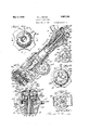
I will :rplain my invention more fully by reference to the accompanying drawings in which Fig. 1 is a view looking toward the upper side of the steering wheel and illus-fio trating a portion thereof and parts of the mechanism that are located above the wheel; Fig. 2 is a. sectional view on line 22 of Fi 1 Fig. 3 is a sectional view on line 33 of Fig. 1; Fig. 4c is a sectional view on a smaller scale, on line l--4 of Fig. 3; Fig. 5 is a sectional View, also on a smaller scale, on line 5-5 of Fig. 3; Fig. 6 is a sectional view on line 66 of Fig. 2; Fig. 7 is a diagram of one circuit arrangement; and Fig. 8 is a sectional view on line 88 of Fig. 2.
The structure illustrated is inclusive of a stationary tubular steering column 1 which is suitably anchored upon the vehicle and above the upper end of which the steering 75 vehicle wheel 2 is mounted and keyed to the hollow vehicle steering shaft 3. This steering shaft is adapted to turn within bearings i and 5 that surround it and are surrounded by the column which carries these hearings. Said steering shaft 3 encloses a hollow rod 6 wiich is coaxial with the shaft and column this hollow rod being spaced apart from the shaft 3 by hearing sleeves 7 and 8 and being held stationary by a set bolt 9 which passes through the lower end of a gear casing 10 which is in fixed relation to the steering column. This gear casing encloses the worm 10 that is fixed upon the steering shaft 3 and the worm wheel 10 through which the shaft 3 and the worm 10 operate the steering ground wheels. Another hollow shaft 11 is surrounded by the .aforesaid column, shaft and hollow rod and is coaxial therewith, this shaft 11 being coupled with gas controlling lever mechanism of which a part 12 is illustrated and having a control lever 13 upon its upper end and above the wheel whereby it may be turned. The parts 6 and 11 are spaced by hearing sleeves 14 and 15. A flange 16 100 is fixed upon the upper end of the stationary rod 6 and overlies the bearing sleeve 7, the upper end of the steering shaft 3 and the nut 17 which is screwed upon the upper end of the steering shaft to maintain the steering wheel 2 in assembly with this shaft.
A rotatable and reciprocable rod 18 is journaled within the hollow shaft 11, this rod projecting above the steering hand wheel 2 and considerably below the steering column 1 and steering shaft 3. The extreme upper end of the rod 18 is square in cross section and has sliding fit within a correspondingly shaped recess in the lighting lever 19 to permit said rod to be depressed to sound'the horn without an accompanying movement of the lighting lever, this lever having a bladed portion 19 that extends upon opposite sides of the common axis of the lever and rod 18 whereby it may be pressed upon in the same rotary direction by a thumb on one side of the axis and the index finger on the opposite side of the axis whereby rod 18 is turned to adjust the lighting circuits.
The horn button 20 is generally cylindrical and hollow, the bottom of the horn button being closed by an end wall 21 which is spaced apart sufficiently from the lever 13 to permit of depression of the button that is sufficient to close the horn circuit. The upper portion of the horn button is formed with a central circular cavity or recess which is co-axial with the button and in which the bladed portion 19 of the lighting lever is received in order that it may not protrude to an undesirable extent above the button and interfere with ready accessibility to the button. The end wall 21 of the horn button has a circular hole through which a reduced circular portion 22 of the rod 18 may turn, the button wall 21 being engageable with the larger portion of the rod 18 that is immediately below the rod portion 22 so that when the button is depressed, said rod may be depressed to sound the horn. Screws 23 are screwed into the stationary flange 16 and have smooth cylindrical portions 24 which have snug sliding fit within circular holes formed in the button wall 21 whereby said button is prevented from turning while being free to be moved reciprocably. Te top portion of the button is thus available foruse as an escutcheon indicating the different lightcircuit adjusting positions to which the lighting lever 19 and particularly the gripping portion 19 of the lever may be turned, Fig.
1. The screws 23 pass through arcuate slots 25 formed in the lever 13 to permit this lever to be turned. The lighting lever 19 is formed with prongs 26 which pass through arcuate slots 27 in the button wall 24 to be engageable with the lever 13 which serves as a stop to prevent the lever 19 from being in depressing relation to the rod 18. WVhen the lighting lever and horn button are idle, the rod 18 and button 20 are pressed upwardly by means to be hereinafter described, any suitable means being employed for limiting the extent to which this rod and button may be moved upwardly, the heads of the screws 23 taking part in this function, if desired, these screw heads lapping the button wall 21.
Referring particularly to Figs. 3, 4 and 5, it will be observed that the button 20 and rod 18 are together depressible without having any effect upon the lighting lever since the upper end of the rod 18 is in sliding relation to this lever. It will also be observed that the lighting lever can not be depressed to depress the rod owing to the engagement of the prongs 26 with the lever 13. The lighting lever, when turned, has no influence upon the button in the structure as shown, though the invention is not to be thus limited.
The switchin mechanism which is con-- trolled by the rod 18 is carried at the lower end of a bracket structure 31 which is carried upon the lower end of the stationary steering column 1 by being screwed to the gear casing 10. A spring 32 presses upon the rod 18 longitudinally of its axis to normally maintain this rod together with the handle thereon in the uppermost position along the axis of this rod. This spring is also a contact actuator, this actuator being also preferably a contact carrier to which end this spring is in the form of a. resilientmetallic plate through which a spiral slot 33 is cut around the axis of the rod 18 whereby the central portion of the plate constitutes a flat spring tongue which, by virtue of its resiliency, is normally constrained to remain within the general plane of the plate. A socket 34 is provided upon the lower end of the rod 18, this rod having a split stem 35 which is clamped upon the rod by the screw 36. A disc 37 of insulation is received in said socket and pressed upon by the top side of the central spring tongue portion of the plate 32. The upper end of a metallic plunger contact 38 is received in the inverted cup shaped recess 39 that is centraL ly formed in the plate 32. The contact 38 is received within a metallic spring barrel 40 which also receives a. coiled spring 41 which presses upwardly upon the contact 38, the spring 41 cooperating with the spring tongue portion of the plate 32 in maintaining the rod 18 and horn butt-on 20 in their uppermost position. The plunger contact 38 and the metallic spring barrel 40 are surrounded by a metallic housing 42 which has a lateral extension that is clamped against a contact carrying insulating disc 44 by means of a sleeve rivet 45. The spring barrel 40, itself, has a hollow sleeve continuation 46 which is also riveted to the disc 44. Binding screws 47 and 48 are screwed into said sleeves 45 and 46 to clamp circuit wires 49 and 50 in mechanical and electrical connection with said sleeves. The wire 49 is grounded through the horn or other signaling device 51. The wire is grounded through the horn or other signalling device 51. The wire 50 is grounded through the battery 52. When the horn but ton 20 and rod 18 are depressed, the spiral spring tongue at the central portion of the late 32 is depressed into engagement with the metallic housing 42 whereupon the sig naling device 51 operates. V hen the pres sure upon the horn button 20 is relieved, the plate 32 and the coiled spring 41 restore the horn button and the rod 18 to their uppermost position.
The socket 34 is formed with laterally projecting ears 53 which are received within diametrically opposite recesses 54 that are pro- 'ided within the insulating ring 55 upon which the plate 32 is secured, this plate and ring together constituting a contact actuator and carrier. Other" metallic spring barrels 56 are provided with sleeve extensions 60 which are also secured to the disc 44. These spring barrels contain springs similar to the spring 41 aforesaid, which press upwardly upon the plunger contacts 62, 63, 64 and 65 which, in turn, press upwardly against the insulating ring 55 or against the plate 32, ac cording to the position to which this ring is turned consequent upon turning the rod 18. Said spring press-ed contacts 62, 63, 64 and 65 press the ring 55 against the uppermost or end wall 66 of an inverted cup whose cylindrical wall 67 surrounds the ring 55 and the disc 44, this disc constituting a closure that is clinched upon the rim of the cup. The cup wall 66 has an annular extension 68 which is secured to the bracket structure 31 by the rivets 69. VVater-proof packing 70 is contained in the annular channel that is defined within said annular extension 68.
The plate 32 is provided with fingers 71, 72, and 73 which are clinched into engagement with the ring 55. When the switch is in the adjustment illustrated in Fig. 7 all of the circuits are open, the signaling circuit being adapted to be closed in the manner hitherto described following the depression of the rod 18. When said rod is turned by turning the lighting lever 19, the socket 34, through the intermediation of its ears 53 and the recesses 54, turns the ring 55 to adjust the lighting circuits, this ring being preferably confined to a fixed plane of rotation, the signaling circuit being closable merely by depressing the central portion of the plate 32 without any consequent depression of the ring 55. When said ring and the plate 32 having been turned to bring the finger 71 into connection with the contacts 62 and 63, two circuits are established, one circuit including the grounded battery 52 through the wire 50, the contact 38, the plate 32, the contact 62, and the grounded tail lamp 74. The other circuit includes the grounded battery 52, the wire 50, the contact 38, the plate 32, the contact 63, the dimming resistance 75, the contact 65, and the grounded head lamps 76 that are in parallel, these lamps then glowing dimly. hen these two circuits are thus established, the contact fingers 72 and 73 are out of circuit. When the ring 55 and plate 32 are turned to bring the contact finger 72 into connection with the contact 65, the contact 63 is out of circuit whereby the dimming circuit is opened, a circuit for brightly luminating the lamps 76 then being established and which is inclusive of the grounded battery 52, the contact 38, the plate 32, the contact 65 and said lamps 7 6, in parallel. 32 are turned to bring the finger 7.3 into engagement with the contact 64, the lamps 76 are both out of circuit and the parking lamps 77 are included in circuit, this circuit containing the grounded battery 52, the contact 38, the plate 32, the contact 64 and said lamps 77 which are grounded and in parallel.
It is observable that the horn 51 may be sounded when the ring 55 and plate 32 are turned to any position. The plate 32 is also formed with other inverted cup shaped recesses 78 in which the lighting circuit contacts 62, 63, 64, and 65 or certain of them are receivable when any of the lighting circuits are closed, the recesses 78 cooperating to hold the contact carrier or actuator 32, 55 in lighting circuit closing position. The ring 55 is itself provided with inverted cup shaped depressions 79 which also receive said lighting circuit contacts 62, 63, 64 and 65 or cor--- tain of them to further hold said contacts carrier or actuator 32, 55 in the position to which it is turned.
As has hitherto been stated, the signaling circuit may be operated with the contact carrier or actuator 32, 55 when turned to any position. It is also apparent that the lighting circuits may be adjusted while the signaling circuits is closed as well as when it is opened.
from the invention.
Having thus described my invention, I claim:
1. The combination with the steering shaft of an automotive vehicle; of a hand wheel coupled with said shaft for turning it; switching means adapted to control the sigi aling circuit of the Vehicle and inclusive of an operating push button d sposed at the;
ciprocable along the steering shaft to con l/Vhen the ring 55 and plate Changes may be made without departing trol the signalling circuit and rotatable to control the lighting circuit; said button being assembled with the rod to push the rod thereby to close the signaling circuit; and said lever having a portion passing thru said button provided with thumb and finger engaging portions upon opposite sides of its axis and being coupled with the rod to turn it to control the lighting circuit.
2. The combination with the steering shaft of an automotive vehicle; of a hand wheel coupled with said shaft for turning it; switching means adapted to control the signaling circuit of the vehicle and inclusive of an operating push button disposed at the front side of said wheel and movable along the axis of the steering shaft; and switching means adapted to control the lighting circuit of the vehicle and inclusive of a switch lever mounted to be rotatable upon an axis that extends along the steering shaft and accessible for operation above the aforesaid wheel, both of said switching means including an operating rod common thereto which is reciprocable along the steering shaft to control the signaling circuit and rotatable to control the lighting circuit; said button being assembled with the rod to push the rod to close the signaling circuit and being provided with a cavity in its upper portion; and said lever having a portion received in said cavity and being coupled with the rod to turn it to control the lighting circuit.
3. The combination with the steering shaft of an automotive vehicle; of a hand wheel coupled with said shaft for turning it; switching means adapted to control the signaling circuit of the vehicle and inclusive of an operating push button disposed at the front side of said wheel and movable along the axis of the steering shaft; and switching means adapted to control the lighting circuit of the vehicle and inclusive of a switch lever mounted to be rotatable upon an axis that extends along the steering shaft and accessible for operation above the aforesaid wheel, both of said switching means including an operating rod common thereon which is reciprocable along the steering shaft to control the signaling circuit and rotatable to control the lighting circuit; said button being provided with a cavity in its upper portion and being assembled with the rod to push the rod to close the signaling circuit; and said lever being provided with thumb and finger engaging portions upon opposite sides of its axis which are received in said cavity, and being coupled with the rod to turn it to control the lighting circuit.
4:- The combination with the steering shaft of an automotive vehicle; of a hand wheel coupled with said shaft for turning it; switching means adapted to control the signaling circuit of the vehicle and inclusive of an operating push button disposed at the front side of said wheel and movable along the axis of the steering shaft; and switching means adapted to control the lighting circuit of the vehicle and inclusive of a switch lever mounted to be rotatable upon an axis that extends along the steering shaft and accessible for operation from above the aforesaid wheel, both of said switching means including an operating rod common thereto which is reciprocable along the steering shaft to control the signaling circuit and is rotatable to control the lighting circuit, said button being assembled with the rod to push the rod to close the signaling circuit and said lever being coupled with the rod to turn it to control the lighting circuit and having a portion passing through said button. 7
5. The combination with the steering shaft of an automotive vehicle; of a hand wheel coupled with said shaft for turning it switching means adapted to control the signaling circuit of the vehicle and inclusive of an operating push button disposed at the front side of said wheel and movable along the axis of the steering shaft; and switching means adapted to control the lighting circuit of the vehicle and inclusive of a switch lever mounted to be rotatable upon an axis that extends along the steering shaft and accessible for operation above the aforesaid wheel, both of said switching means including an operating rod common thereto which is reciproeable along the steering shaft to control the signaling circuit and rotatable to control the lighting circuit; said button surrounding the lever and being assembled with the rod to close the signaling circuit; said lever being coupled with the rod to turn it to control the lighting circuit; and means engageable by the lever and operative to restrain said lever against material movement along the lever axis.
6. The combination with the steering shaft of an automotive vehicle; of a hand wheel coupled with said shaft for turning it; switching means adapted to control the signaling circuit of the vehicle and inclusive of an operating push button disposed at the front side of said wheel and movable along the axis of the steering shaft; and switching means adapted to control the lighting circuit of the vehicle and inclusive of a switch lever mounted to be rotatable upon an axis that extends along the steering shaft and accessible for operation above the aforesaid wheel, both of said switching means including an operating rod common thereto which is reciproeable along the steering shaft to control the signaling circuit and rotatable to control the li ghting circuit; said button being disposed about the lever and being assembled with the rod to push the rod to close the signaling circuit; and means operatively holding said button against rotation; said lever being coupled with the rod to turn it to control the lighting circuit.
7. The combination with the steering shaft of an automotive vehicle; of a hand wheel coupled With said shaft for turning switching means adapted to control the signaling circuit of the vehicle and inclusive of an operating push button disposed the front side of said wheel and movable along the axis of the steering shaft; and switching means adapted to control the lighting circuit of the vehicle and inclusive of a switch lever mounted to be rotatable upon an axis that extends along the steering shaft and accessible for operation above the aforesaid wheel, both of said switching means including an operating rod common thereto which is reciprocable along the steering shaft to control the signaling circuit and rotatable to control the lighting circuit; said button being assembled with the rod to push the rod to close the signalin circuit; means operatively holding the button against rotation; said lever being arranged substantially within the button and being coupled with the rod to turn it to control the lighting circuit; and means restraining the lever against material movement along the lever axis.
8. The combination with the steering shaft of an automotive vehicle; of a hand wheel coupled With said shaft for turning it; switching means adapted to control the signaling circuit of the vehicle and inclusive of an operating push button disposed at the front side of said wheel and movable along the axis of the steering shaft; and switching means adapted to control the lighting circuit of the vehicle and inclusive of a switch lever mounted to be rotatable upon an axis that extends along the steering shaft and accessible for operation above the aforesaid wheel, both of said switching means including an operating rod common thereto which is reciprocable along the steering shaft to control the signaling circuit and rotatable to control the lighting circuit; said button being assembled with the rod to push the rod to close the signaling circuit; means operative to restrain the button from rotation; said button being pro vided with indications of lighting circuit adjustments corresponding to and located at the different circuit adjusting positions of the lever; and said lever being arranged substantially within the button and being coupled with the rod to turn it to different circuit adjustments to control the lighting circuit.
9. The combination with the steering shaft of an automotive vehicle; of a hand wheel coupled with said shaft for turning it switching means adapted to control the signaling circuit of the vehicle and inclusive of an operating push button disposed at the front side of said wheel and movable along the axis of the steering shaft; and switching means my name.
GEORGE L. CRAGG.
Priority Applications (1)
| Application Number | Priority Date | Filing Date | Title |
|---|---|---|---|
| US252257A US1857043A (en) | 1928-02-06 | 1928-02-06 | Circuit controller |
Applications Claiming Priority (1)
| Application Number | Priority Date | Filing Date | Title |
|---|---|---|---|
| US252257A US1857043A (en) | 1928-02-06 | 1928-02-06 | Circuit controller |
Publications (1)
| Publication Number | Publication Date |
|---|---|
| US1857043A true US1857043A (en) | 1932-05-03 |
Family
ID=22955248
Family Applications (1)
| Application Number | Title | Priority Date | Filing Date |
|---|---|---|---|
| US252257A Expired - Lifetime US1857043A (en) | 1928-02-06 | 1928-02-06 | Circuit controller |
Country Status (1)
| Country | Link |
|---|---|
| US (1) | US1857043A (en) |
-
1928
- 1928-02-06 US US252257A patent/US1857043A/en not_active Expired - Lifetime
Similar Documents
| Publication | Publication Date | Title |
|---|---|---|
| US1857043A (en) | Circuit controller | |
| US3805003A (en) | Motorcycle handle signal control rotatable or depressible to actuate signal controlling switches | |
| US2459898A (en) | Means for actuating electrical switches | |
| US1595146A (en) | Flash lamp | |
| US1977887A (en) | Circuit controlling device | |
| US1748014A (en) | Combined lighting and signaling switch mechanism for automotive vehicles | |
| US1853513A (en) | Circuit maker and breaker | |
| US2068632A (en) | Direction indicator switch | |
| US1746887A (en) | Switching mechanism | |
| US1748015A (en) | Combined lighting and signaling switch mechanism for automotive vehicles | |
| US2650836A (en) | Writing pad unit for automobile steering wheels | |
| US2034414A (en) | Switch | |
| US2196705A (en) | Vehicle signal system | |
| US2178854A (en) | Mechanism for operating an electrical signaling system | |
| US1629397A (en) | Headlight-control switch | |
| US2317402A (en) | Electric brake controller | |
| US2274990A (en) | Hand brake signal | |
| US1980323A (en) | Steering wheel signal operating switch | |
| US2182029A (en) | Automobile signal switch | |
| US1676412A (en) | Alarm signal for automobiles | |
| US1572828A (en) | Horn button attachment | |
| US1717918A (en) | Electric switch | |
| US2057000A (en) | Switch construction for automotive vehicles | |
| US1742766A (en) | Controlling apparatus | |
| US2722578A (en) | Vehicle motor starter switch |