US1853513A - Circuit maker and breaker - Google Patents
Circuit maker and breaker Download PDFInfo
- Publication number
- US1853513A US1853513A US176232A US17623227A US1853513A US 1853513 A US1853513 A US 1853513A US 176232 A US176232 A US 176232A US 17623227 A US17623227 A US 17623227A US 1853513 A US1853513 A US 1853513A
- Authority
- US
- United States
- Prior art keywords
- rod
- circuit
- casing
- steering
- shaft
- Prior art date
- Legal status (The legal status is an assumption and is not a legal conclusion. Google has not performed a legal analysis and makes no representation as to the accuracy of the status listed.)
- Expired - Lifetime
Links
Images
Classifications
-
- B—PERFORMING OPERATIONS; TRANSPORTING
- B60—VEHICLES IN GENERAL
- B60Q—ARRANGEMENT OF SIGNALLING OR LIGHTING DEVICES, THE MOUNTING OR SUPPORTING THEREOF OR CIRCUITS THEREFOR, FOR VEHICLES IN GENERAL
- B60Q1/00—Arrangement of optical signalling or lighting devices, the mounting or supporting thereof or circuits therefor
- B60Q1/26—Arrangement of optical signalling or lighting devices, the mounting or supporting thereof or circuits therefor the devices being primarily intended to indicate the vehicle, or parts thereof, or to give signals, to other traffic
- B60Q1/34—Arrangement of optical signalling or lighting devices, the mounting or supporting thereof or circuits therefor the devices being primarily intended to indicate the vehicle, or parts thereof, or to give signals, to other traffic for indicating change of drive direction
- B60Q1/343—Manually actuated switching arrangements therefor
Definitions
- My invention relates to circuit makers and breakers employed in connection with the hand steering wheels of automotive vehicles.
- the invention has for its general object an improved association of a hand operated lever mechanism in controlling relation with the circuit making and breaking mechanism and in which such hand operated lever mechanism is upon the under or far side of the hand steering wheel, so as not to interfere with accessibility to this wheel.
- the invention has for another object the provision of switching mechanism in con trolling relation to lighting and signaling circuits and unitary operating mechanism therefor adjacent the steering wheel and adapted, when operated in one manner, to regulate a lighting circuit and, when operated in another manner, to regulate the signaling circuit.
- the signaling circuit is usually in control of an audible signal such as a horn and in order that the horn may be quickly sounded, the unitary switch operating mechanism is desirably so designed that a signal will be manifested upon slight movement of this switch operating mechanism.
- This switch operating mechanism desirably includes a rod which may be turned upon its axis to control the lighting circuits and may be moved along its axis to control the signaling circuit.
- This rod extends along the steering column from the switching mechanism at a lower portion of the column into proximity to the steering wheel at the upper end of the column where it is assembled with a lever which is mounted to turn in a plane transverse to the axis of the rod to operate the switching mechanism in a manner to control the lighting circuit and which lever is mounted to swing with reference to the rod upon an axis that is transverse to the axis of the rod, the lever being so coupled with the rod that when the lever is manually depressed, it will move the rod longitudinally of its axis to close the signaling circuit, there being automatic means, such as a spring, which will restore the lever from its depressed position to open the signaling circuit.
- the signaling circuit may be established by merely tapping the lever, which may be Serial No. 176,232.
- Figure l is a side elevation showing the preferred embodiment of the invention
- Figure 2 is a longitudinal sectional View of a part of the structure appearing in Figure 1
- Figure 3 is a sectional view on line 33 of Figure 2
- Figure 1 ⁇ is a sectional view on line i-i of Figure 2
- Figure 5 is a sectional view on line 5-5 of Figure 2.
- the switching mechanism shown for purposes of illustration includes a switch contact 2.
- a metallic bridging element 5 is mounted to turn and is so constructed that in one position it will connect the contact 6, which may be connected with a source of current such as a battery, with the contact 2 to cause the head lamps to be in circuit and in another position to be out of engagement with the contact 2 whereby the head lamps are out of circuit.
- the bridging element 5 is carried by a disc of insulation 8 which has a square hole centraliy thereof snugly receiving asquare rod 43, so that when this rod is turned the disc 8 and the bridging element 5 will turn.
- Said disc and bridging element 5 are housed within a switch casing which is inclusive of a cup shaped member 10 and a closure disc 11 of insulation opposite the end wall of the cup.
- the rod 43 has a bearing in a tubular continuation of the cup 10, said rod also having a reduced portion 9 which turns within the disc 11 through which this portion passes.
- the contacts 2 and 6 are spring pressed, these contacts projecting from metallic spring barrels 13 that contain springs which press outwardly upon said contacts which engage either the bridging element 5 or the insulating disc 8 according to the position to which the rod 43 is turned.
- the spring barrels 13 have reduced ends which pass through the insulating disc 11, screws 15 serving to connect these spring barrels with the wiring that pertains to the head lamp circuit and a. horn circuit, for example.
- the rod 43 is not only mounted to turn to control the head lamp circuit, but is reciprocable in a direction angular to its plane of rotation to control the horn or other signaling circuit, horn contacts 17 and 18 being also mounted on the insulating disc 11 and spaced apart thereon. In this instance, the contact 18 also in electrical connection with the contact 6.
- the lower end of the rod 43 carries a metallic bridging element 19 which is normally disengaged from the contacts 17 and 18, but which is brought into engagement with these contacts upon suitable longitudinal movement of the rod.
- a short rod 33 which is journaled within a gear casing 34 that is suitably assembled with the steering column 20 which houses the steering shaft 23 upon which is mounted the steering wheel 22.
- the interior of the gear casing 34 is in communication with the interior of the steering column 20.
- the rod 33 is movable longitudinally of its axis to control the horn circuit and is rotatable upon its axis to control the head lamp circuit, as will shortly appear.
- a coil spring 35 has its upper end in abutting engagement with the top wall of the gear casing 34 and has its lower end in engagement with a segmental pinion 36 which is fixed upon the lower end of the rod 33, this pinion 36 having abutting engagement with the bottom wall of the gear casing.
- the pinion 36 is in mesh with a segmental pinion 37 which is fixed on the upper end of a rod 38 located within the steering column 20 and that projects through the lower wall of the gear casing 34.
- the lower end of the rod 38 carries a segmental pinion 39 which is in mesh with a segmental pinion 40 that is contained within a casing 41 which receives the casing 10.
- a spring 42 presses the pinion 40 downwardly to place the rod 43 in its lower position.
- the rods 33 and 38 are coupled to move longitudinally of their axes by the hooding of the pinions 37 and 39, whereby these pinions and the pinions 36 and T0 are in thrusting engagement, as illustrated.
- the handle 30 which is pivotally connected to the rod 33, at 31, is moved in the plane of the axis of the rod'33, the handle 30 will fulcrum on its hub 32 and the rods 33, 38, and 43 will be moved along their axes to close the horn circuit, the spring 35 operating to open the horn circuit when the handle is released.
- the handle 30 is turned, obviously the bridging member 5 will also be turned to connector disconnect contacts 2 and 6 to control the head lamp cir cuit.
- the handle 30 may be moved in the plane of the axis ofthe rod 33 in any position to which the handle is turned upon the axis of the rod 33, so that the horn may be operated in any position of the handle. 7
- the steering column and steering shaft may be held in position by means of a clamping bracket 24 which is secured to and depends from the panel 25 upon the vehicle body.
- the handle 30 Since the under or far side of the steering wheel is the side away from the driver, the handle 30 is out of reach of accidental operation. hen I say that the handle is upon the under or far side of the steering wheel I mean that the steering wheel is between the driver and the handle.
- a circuit maker and breaker for an automotive vehicle employing a stationary hollow steering column through which a. steering shaft passes that carries a hand operated steering wheel, including complemental contacts one of which is rotatable in a plane that is transverse to the axis of the steering shaft and into and out of engagement with the other and complemental contacts one of which is movable into and out of engagement with the other by movement along the steering shaft; a rod contained within t steering column between said column and steering shaft mounted to turn and also to tudinally movable and coupled by intern eshing gears withthe rotatable contact to turn the same when the rod is turned and coupled by hooding the underside of the rod gear with the other movable contact to move the same when the rod is moved along the steering shaft, said rod being located between the far side of the steering wheel and said contacts; a bracket upon the steering column upon the far side of the steering wheel and on which said rod is mounted to turn; and a hand operated lever coupled by intermeshing gears with said rod to turn it and move it longitudinally by
- a circuit maker and breaker for an automotive vehicle employing a stationary hollow steering column through which a steering shaft passes that carries a hand operated steering wheel, including a casing.
Landscapes
- Engineering & Computer Science (AREA)
- Mechanical Engineering (AREA)
- Steering Controls (AREA)
Description
April 12, 1932.
H. A. DOUGLAS CIRCUIT MAKER AND BREAKER Filed March 17, 1927 Patented Apr. 12, 1932 UNITED STATES HARRY A. DOUGLAS, OF BRONSON, MICHIGAN CIRCUIT MAKER AND BREAKER Application filed March 17, 1927.
My invention relates to circuit makers and breakers employed in connection with the hand steering wheels of automotive vehicles. The invention has for its general object an improved association of a hand operated lever mechanism in controlling relation with the circuit making and breaking mechanism and in which such hand operated lever mechanism is upon the under or far side of the hand steering wheel, so as not to interfere with accessibility to this wheel.
The invention has for another object the provision of switching mechanism in con trolling relation to lighting and signaling circuits and unitary operating mechanism therefor adjacent the steering wheel and adapted, when operated in one manner, to regulate a lighting circuit and, when operated in another manner, to regulate the signaling circuit. The signaling circuit is usually in control of an audible signal such as a horn and in order that the horn may be quickly sounded, the unitary switch operating mechanism is desirably so designed that a signal will be manifested upon slight movement of this switch operating mechanism. This switch operating mechanism desirably includes a rod which may be turned upon its axis to control the lighting circuits and may be moved along its axis to control the signaling circuit. This rod extends along the steering column from the switching mechanism at a lower portion of the column into proximity to the steering wheel at the upper end of the column where it is assembled with a lever which is mounted to turn in a plane transverse to the axis of the rod to operate the switching mechanism in a manner to control the lighting circuit and which lever is mounted to swing with reference to the rod upon an axis that is transverse to the axis of the rod, the lever being so coupled with the rod that when the lever is manually depressed, it will move the rod longitudinally of its axis to close the signaling circuit, there being automatic means, such as a spring, which will restore the lever from its depressed position to open the signaling circuit. Thus the signaling circuit may be established by merely tapping the lever, which may be Serial No. 176,232.
done with the lever in any position to which it is turned to adjust the lighting circuit.
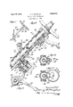
I will explain my invention more fully by reference to the accompanying drawings in which Figure l is a side elevation showing the preferred embodiment of the invention; Figure 2 is a longitudinal sectional View of a part of the structure appearing in Figure 1; Figure 3 is a sectional view on line 33 of Figure 2; Figure 1} is a sectional view on line i-i of Figure 2; Figure 5 is a sectional view on line 5-5 of Figure 2.
The switching mechanism shown for purposes of illustration includes a switch contact 2. A metallic bridging element 5 is mounted to turn and is so constructed that in one position it will connect the contact 6, which may be connected with a source of current such as a battery, with the contact 2 to cause the head lamps to be in circuit and in another position to be out of engagement with the contact 2 whereby the head lamps are out of circuit.
The bridging element 5 is carried by a disc of insulation 8 which has a square hole centraliy thereof snugly receiving asquare rod 43, so that when this rod is turned the disc 8 and the bridging element 5 will turn. Said disc and bridging element 5 are housed within a switch casing which is inclusive of a cup shaped member 10 and a closure disc 11 of insulation opposite the end wall of the cup. At one end, the rod 43 has a bearing in a tubular continuation of the cup 10, said rod also having a reduced portion 9 which turns within the disc 11 through which this portion passes. The contacts 2 and 6 are spring pressed, these contacts projecting from metallic spring barrels 13 that contain springs which press outwardly upon said contacts which engage either the bridging element 5 or the insulating disc 8 according to the position to which the rod 43 is turned. The spring barrels 13 have reduced ends which pass through the insulating disc 11, screws 15 serving to connect these spring barrels with the wiring that pertains to the head lamp circuit and a. horn circuit, for example. The rod 43 is not only mounted to turn to control the head lamp circuit, but is reciprocable in a direction angular to its plane of rotation to control the horn or other signaling circuit, horn contacts 17 and 18 being also mounted on the insulating disc 11 and spaced apart thereon. In this instance, the contact 18 also in electrical connection with the contact 6. The lower end of the rod 43 carries a metallic bridging element 19 which is normally disengaged from the contacts 17 and 18, but which is brought into engagement with these contacts upon suitable longitudinal movement of the rod.
To manipulate the rod 43, in accordance with my invention, I have here shown a short rod 33 which is journaled within a gear casing 34 that is suitably assembled with the steering column 20 which houses the steering shaft 23 upon which is mounted the steering wheel 22. The interior of the gear casing 34 is in communication with the interior of the steering column 20. The rod 33 is movable longitudinally of its axis to control the horn circuit and is rotatable upon its axis to control the head lamp circuit, as will shortly appear.
A coil spring 35 has its upper end in abutting engagement with the top wall of the gear casing 34 and has its lower end in engagement with a segmental pinion 36 which is fixed upon the lower end of the rod 33, this pinion 36 having abutting engagement with the bottom wall of the gear casing. The pinion 36 is in mesh with a segmental pinion 37 which is fixed on the upper end of a rod 38 located within the steering column 20 and that projects through the lower wall of the gear casing 34. The lower end of the rod 38 carries a segmental pinion 39 which is in mesh with a segmental pinion 40 that is contained within a casing 41 which receives the casing 10. A spring 42 presses the pinion 40 downwardly to place the rod 43 in its lower position.
The rods 33 and 38 are coupled to move longitudinally of their axes by the hooding of the pinions 37 and 39, whereby these pinions and the pinions 36 and T0 are in thrusting engagement, as illustrated. It will be apparent that when the handle 30, which is pivotally connected to the rod 33, at 31, is moved in the plane of the axis of the rod'33, the handle 30 will fulcrum on its hub 32 and the rods 33, 38, and 43 will be moved along their axes to close the horn circuit, the spring 35 operating to open the horn circuit when the handle is released. When the handle 30 is turned, obviously the bridging member 5 will also be turned to connector disconnect contacts 2 and 6 to control the head lamp cir cuit. It will be further apparent that the handle 30 may be moved in the plane of the axis ofthe rod 33 in any position to which the handle is turned upon the axis of the rod 33, so that the horn may be operated in any position of the handle. 7
As illustrated, the steering column and steering shaft may be held in position by means of a clamping bracket 24 which is secured to and depends from the panel 25 upon the vehicle body.
Since the under or far side of the steering wheel is the side away from the driver, the handle 30 is out of reach of accidental operation. hen I say that the handle is upon the under or far side of the steering wheel I mean that the steering wheel is between the driver and the handle.
Havingthus described my invention, I claim:
1. A circuit maker and breaker for an automotive vehicle employing a stationary hollow steering column through which a. steering shaft passes that carries a hand operated steering wheel, including complemental contacts one of which is rotatable in a plane that is transverse to the axis of the steering shaft and into and out of engagement with the other and complemental contacts one of which is movable into and out of engagement with the other by movement along the steering shaft; a rod contained within t steering column between said column and steering shaft mounted to turn and also to tudinally movable and coupled by intern eshing gears withthe rotatable contact to turn the same when the rod is turned and coupled by hooding the underside of the rod gear with the other movable contact to move the same when the rod is moved along the steering shaft, said rod being located between the far side of the steering wheel and said contacts; a bracket upon the steering column upon the far side of the steering wheel and on which said rod is mounted to turn; and a hand operated lever coupled by intermeshing gears with said rod to turn it and move it longitudinally by hooding the upper side of the rod gear and also located upon the far side of the steering wheel, said lever being rotatable in a plane transverse to the axis of the steering shaft to turn said rod and also rotatable in a plane along the steering shaft to force longitudinal movement of the rod.
2. A circuit maker and breaker for an automotive vehicle employing a stationary hollow steering column through which a steering shaft passes that carries a hand operated steering wheel, including a casing.
mounted upon the exterior of the steering column adjacent the steering wheel provided with a portion adapted to enter within the steering column, a second casing spaced apart from the first casing mounted upon the steer ing column and havin a portion adapted to enter within said column, a rod mounted to rotate and to move longitudinally in guides provided therefor in the respective portions of the casing entering within the steering column, a shaft mounted in the first named casing parallel to said rod provided with a hand operated lever coupled thereto upon the upper side of the casing and adapted to impart rotative and longitudinal movement to said shaft, a gear upon the other end of the shaft meshing with the gear carried upon the upper end of the rod, a spring interposed between the gear on the shaft and the upper side of the casing to maintain the gear in contact with the lower side of the casing, said gear upon the upper end of the shaft provided with a hood adapted to engage the gear teeth of the shaft gear when moved by the handle longitudinally against the pressure of the spring and impart a similar longitudinal movement to the rod, complemental contacts mounted in the second named casing one of which is rotatable in a plane that is transverse to the axis of the steering shaft and into and out of engagement with the other and complemental contacts one of which is movable into and out of engagement with the other by'movement along a steering shaft, a shaft mounted iIf this second named casing for both rotative and longitudinal movement and adapted to rotate the rotatable contact and having a sliding transverse movement therewith adapted to move one member of the other complemental contacts into engagement, a spring between the upper end of the shaft and upper end of the casing normally maintaining the movable contact out of engagement, a gear mounted upon the upper end of said shaft intermeshing with a gear mounted upon the lower end of the rod, said gear hooded upon the underside adapted to engage the teeth of the shaft gear and move the shaft upward when the rod is moved upward, whereby rotation of the hand lever imparts a similar rotation to the rotatable set of complemental contacts to make and break one circuit and whereby depression of the hand operating lever imparts an upward movement to the rod against the tension of the two springs in the respec tive cases and through the hooded gears upon said shaft closes the other set of complemental contacts to close another circuit.
In witness whereof, I hereunto subscribe my name.
HARRY A. DOUGLAS.
Priority Applications (1)
| Application Number | Priority Date | Filing Date | Title |
|---|---|---|---|
| US176232A US1853513A (en) | 1927-03-17 | 1927-03-17 | Circuit maker and breaker |
Applications Claiming Priority (1)
| Application Number | Priority Date | Filing Date | Title |
|---|---|---|---|
| US176232A US1853513A (en) | 1927-03-17 | 1927-03-17 | Circuit maker and breaker |
Publications (1)
| Publication Number | Publication Date |
|---|---|
| US1853513A true US1853513A (en) | 1932-04-12 |
Family
ID=22643531
Family Applications (1)
| Application Number | Title | Priority Date | Filing Date |
|---|---|---|---|
| US176232A Expired - Lifetime US1853513A (en) | 1927-03-17 | 1927-03-17 | Circuit maker and breaker |
Country Status (1)
| Country | Link |
|---|---|
| US (1) | US1853513A (en) |
Cited By (7)
| Publication number | Priority date | Publication date | Assignee | Title |
|---|---|---|---|---|
| US2489617A (en) * | 1947-09-30 | 1949-11-29 | Walter L Byram | Electric control device for signal lights on automotive vehicles |
| US2662189A (en) * | 1951-03-20 | 1953-12-08 | Gen Motors Corp | Engine starter control |
| US2775664A (en) * | 1952-10-30 | 1956-12-25 | Gen Motors Corp | Neutral safety and back-up light switch |
| US2792463A (en) * | 1952-08-05 | 1957-05-14 | Gen Motors Corp | Safety switch |
| US2863013A (en) * | 1955-09-14 | 1958-12-02 | Gen Motors Corp | Direction signal |
| US5259262A (en) * | 1992-05-22 | 1993-11-09 | Itt Corporation | Non-involute gear |
| US6444929B1 (en) | 2000-03-23 | 2002-09-03 | Valeo Electrical Systems, Inc. | Multi-function stalk switch with zero backlash drive gear pair |
-
1927
- 1927-03-17 US US176232A patent/US1853513A/en not_active Expired - Lifetime
Cited By (8)
| Publication number | Priority date | Publication date | Assignee | Title |
|---|---|---|---|---|
| US2489617A (en) * | 1947-09-30 | 1949-11-29 | Walter L Byram | Electric control device for signal lights on automotive vehicles |
| US2662189A (en) * | 1951-03-20 | 1953-12-08 | Gen Motors Corp | Engine starter control |
| US2792463A (en) * | 1952-08-05 | 1957-05-14 | Gen Motors Corp | Safety switch |
| US2775664A (en) * | 1952-10-30 | 1956-12-25 | Gen Motors Corp | Neutral safety and back-up light switch |
| US2863013A (en) * | 1955-09-14 | 1958-12-02 | Gen Motors Corp | Direction signal |
| US5259262A (en) * | 1992-05-22 | 1993-11-09 | Itt Corporation | Non-involute gear |
| JP3001636B2 (en) | 1992-05-22 | 2000-01-24 | アイティーティー・インダストリーズ・インコーポレーテッド | Gear pair |
| US6444929B1 (en) | 2000-03-23 | 2002-09-03 | Valeo Electrical Systems, Inc. | Multi-function stalk switch with zero backlash drive gear pair |
Similar Documents
| Publication | Publication Date | Title |
|---|---|---|
| US2324819A (en) | Circuit controller | |
| US1853513A (en) | Circuit maker and breaker | |
| US2964601A (en) | Electrically operated marine engine gear shift | |
| US2064735A (en) | Signal device | |
| US1973299A (en) | Vehicle signal | |
| US2813942A (en) | Switch for actuating an electrically operable clutch of a vehicle or the like | |
| US1977887A (en) | Circuit controlling device | |
| US2152450A (en) | Switch | |
| US2794082A (en) | Automotive signalling system | |
| US2246255A (en) | Steering wheel | |
| US2722578A (en) | Vehicle motor starter switch | |
| US1470059A (en) | Electric switch | |
| US1717918A (en) | Electric switch | |
| US1837634A (en) | Electric switch | |
| US2578423A (en) | Directional signal switch assembly for vehicles | |
| US1748015A (en) | Combined lighting and signaling switch mechanism for automotive vehicles | |
| US2167031A (en) | Circuit closer for use in a signaling device for motor vehicles | |
| US1570107A (en) | Circuit-controlling means for signaling devices | |
| US2035266A (en) | Circuit controlling device for an automobile signaling mechanism | |
| US1919209A (en) | Switching mechanism for automotive vehicles | |
| US1710407A (en) | Combined lighting and signaling mechanism for automotive vehicles | |
| US1239236A (en) | Electric-circuit closer for automobiles. | |
| US1745807A (en) | Controller switch for automotive vehicles | |
| US1748014A (en) | Combined lighting and signaling switch mechanism for automotive vehicles | |
| US1638091A (en) | Signal-controlling mechanism for automobiles |