US1857030A - Carburetor - Google Patents
Carburetor Download PDFInfo
- Publication number
- US1857030A US1857030A US399552A US39955229A US1857030A US 1857030 A US1857030 A US 1857030A US 399552 A US399552 A US 399552A US 39955229 A US39955229 A US 39955229A US 1857030 A US1857030 A US 1857030A
- Authority
- US
- United States
- Prior art keywords
- chamber
- fuel
- carburetor
- air
- mixing
- Prior art date
- Legal status (The legal status is an assumption and is not a legal conclusion. Google has not performed a legal analysis and makes no representation as to the accuracy of the status listed.)
- Expired - Lifetime
Links
Images

Classifications
-
- F—MECHANICAL ENGINEERING; LIGHTING; HEATING; WEAPONS; BLASTING
- F02—COMBUSTION ENGINES; HOT-GAS OR COMBUSTION-PRODUCT ENGINE PLANTS
- F02M—SUPPLYING COMBUSTION ENGINES IN GENERAL WITH COMBUSTIBLE MIXTURES OR CONSTITUENTS THEREOF
- F02M15/00—Carburettors with heating, cooling or thermal insulating means for combustion-air, fuel, or fuel-air mixture
- F02M15/02—Carburettors with heating, cooling or thermal insulating means for combustion-air, fuel, or fuel-air mixture with heating means, e.g. to combat ice-formation
- F02M15/027—Air or air-fuel mixture preheating
-
- F—MECHANICAL ENGINEERING; LIGHTING; HEATING; WEAPONS; BLASTING
- F02—COMBUSTION ENGINES; HOT-GAS OR COMBUSTION-PRODUCT ENGINE PLANTS
- F02M—SUPPLYING COMBUSTION ENGINES IN GENERAL WITH COMBUSTIBLE MIXTURES OR CONSTITUENTS THEREOF
- F02M19/00—Details, component parts, or accessories of carburettors, not provided for in, or of interest apart from, the apparatus of groups F02M1/00 - F02M17/00
- F02M19/02—Metering-orifices, e.g. variable in diameter
- F02M19/0235—Arrangements of several spray nozzles not provided for in F02M3/00 or F02M11/00
-
- F—MECHANICAL ENGINEERING; LIGHTING; HEATING; WEAPONS; BLASTING
- F02—COMBUSTION ENGINES; HOT-GAS OR COMBUSTION-PRODUCT ENGINE PLANTS
- F02M—SUPPLYING COMBUSTION ENGINES IN GENERAL WITH COMBUSTIBLE MIXTURES OR CONSTITUENTS THEREOF
- F02M29/00—Apparatus for re-atomising condensed fuel or homogenising fuel-air mixture
- F02M29/02—Apparatus for re-atomising condensed fuel or homogenising fuel-air mixture having rotary parts, e.g. fan wheels
Definitions
- This invention appertains to improvements in carburetors generally, and has for its main object to provide a type of the same which will operate at a much higher-efficiency than L6 the now known types of such devices, by reason of the inclusion in its structure of means allowing for a greater range of and nicety in the proportionment of the liquid fuel and air between extremely low and high speeds- 10 of an internal combustion engine with which it is employed, and also of a means for effect-- ing a more intimate mixture of the fuel and air just prior to the passage of the resultant fuel to and through the intake manifold of the engine.
- Another object of the invention is to provide a carburetor of the class set forth, which will greatly' facilitate the starting'up of an engine at all times and especially in cold weather, by reason of the embodying in the same of a means for vaporizing the raw liquid fuel by electrically preheating it to vaporized state just before its initial mixing with the air supply.
- a further object of the invention is to provide a carburetor as hereinbefore characterized, which also embodies a means, such as a centrifuge, for mechanically mixing'the initially formed and preheated fuel vapor prior 80 to its passage from the carburetor. to the intake manifold of the engine, whereby the effectiveness of the fuel supply will be greatly increased.
- a still further object of the invention resides in the rovisio'n of a means for utilizing a portion 0 the hot exhaust gases from the exhaust manifold of the engine for the continued heating of the fuel supply, after the initial or preheating means'has been rendered inoperative and thereafter during an entire period of operation of the engine, the heat from the exhaust gases bein effectively applied to the raw fuel after t e same manner as that of applying the initial heat thereto as well as to the fuel mixture just prior to its passage from the carburetor to the intake manifold of the engine.
- Another object of the invention lies in the provision of means for applying the heat from the exhaust gases from the engine to the tional form of internal combustion engine
- a further object of the invention is to provide a raw fuel receiving chamber within the body of the carburetor apart from the usual float chamber therein but in communication with the latter, whereby the level of the raw fuel will be uniform in both and under the control of the single needle valve operatively connected to the float and the raw fuel within the float chamber will not be subjected to the' heat employed in either instance aforesaid.
- a still further object of the invention is to so locate the float chamber of the carburetor that the same will be kept in a cool state by the air taken into the carburetor preferably through a high speed air intake manifold forming a part of the latter and on a side thereof removed from a low speed air intake manifold.
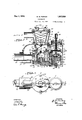
- Figure 1 is a side-elevation of a convenshowing a practical embodiment of the improved carburetor as installed thereon;
- Figure 2 is an elevation of the low speed manifold side of the carburetor, showing the exhaust pipe connection leading therefrom to the exhaust muflier in cross section;
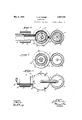
- Figure 3 is a vertical section, taken on the line 3-3 of Figure 4;
- Figure 4 is a vertical section, taken on the line 4--4 of Figure 5;
- Figure 5 is a top plan view
- Figure 6 is a horizontal section, taken on the line 6-6 of Figure 4;
- Figure 7 is a similar section, taken on the line 7-7 of Figure; and 1:0
- F1 re 8 is a bottom plan view.
- the embodiment of the invention is generally constituted in a central body portion A, alow speed air intake manifold B, bolted as at 10, to one side of the lower portion of the central portion A; a combined high s eed air intake manifold and float chamber bolted, as at 11, at the opposite side of the central portion A; and an attaching flange member D bolted, as at 12, to the upper open end of the latter and having bolt receiving openings 13 formed in the'flange proper for secured engagement to the inlet end of the usual fuel intake manifold a of an internal combust on engine.
- the central body portion A comprises a metal casting formed to provide a substantially closed fuel receiving and heating chamber 14 centrally of its lower end portion, which constitutes the initial fuel vaporizing chamber of the carburetor and receives its supply of raw fuel or gasolene from the float chamber 15, the latter beinglocated in the lower side of the hi h speed air intake manifold C.
- the cham er 14 is connected with the lower side of the float chamber 15 through a connecting passageway 16 which passes laterally beneath the lower end of the body portion A to a point at the center of the bottom thereof where it passes upwardly for the discharge of the liquid fuel into the chamber 14 from the upper conical end of a hollow cylindrical wall portion 17 rising i11- wafldly of the chamber 14 from the bottom wa
- Liquid fuel is supplied to the float chamber 15 from a supply pipe 18 openin inwardly through the bottom wall thereo and the ow from the attachedend of the pipe 18 is controlled by'a needle valve 19 rising'centrally within the chamber and passing in secured relation to and upwardly through a collar 20 for the disposalof its upper end in a gulde constituted in an upwardly depres (1 portion 21 formed in the top wall of if! chamber 15.
- This'collar the usual manner from the inner end of oppositely arrangedangled levers 22 which are plvotally supported in brackets 23 at the lower side of the top'wall of the float cham-
- the level of the in 1 d 'tted't th ch 'b 1 'l 1) 3th i I e a m1 0 8 er 4 W11 e inwardly directed end portion conveys the same as that in the float chamber 15L Passing angular'lybutward from the upper side of the chamber '14 is a fuel outlet passageway25 which connects at its outer ⁇ end "with a low speed nozzle 26; and in the same manner, from the opposite side of the chamber 14 a fuel outlet passageway 27 connects 20 is supported in 'with a high speed nozzle 28 at its outer end,
- the upper side of the mixing chamber 31 is in open communication with the lower end of said final mixing and vaporizing.chamber 32 about a spider or cross bar 33, which carries an adjustable bearing or trunnion 34 at its center for the supporting thereby of the lower pointed end of a vertical shaft 35 of a whirling mixing device or centrifuge, the upper end of the shaft 35 being also pointed for bearing engagement in a depression formed in the lower thickened central portion of a spider or cross bar 36 spanning the lower end of the bore in the attaching flange member B;
- a propeller or bladed fan 37 Mounted on the lower end of the shaft 35 is a propeller or bladed fan 37 and above the same a series of vertically spaced agitator blades or vanes 38, the latter being of a graduated length corresponding to the upwardly increasing diameter of the hollow interior of the chamber 32.
- the low speed air intake manifold Bis in this point to atmosphere while its upward 1 incoming air to the venturi tube 40 and acts to draw fuel upwardly of the low speed nozzle venturi and preferably at an angle to the path of flow of the air for the purpose.
- the high speed intake manifold C has an outwardly nippled opening 41 formed in'its upper side, and the same is interiorly screw threaded to seat therein a cap 42, which has spanner wrench recesses 42 in its upper face to facilitate its removal, replacement and adjustment.
- a tubular guide 43 which has its bore opening upwardly through the horizontal wall of the cap to receive therethrough a valve stem 44, the latter carrying a diaphragm valve member 45 at its lower end.
- This valve member 45 is arranged to normally seat within the upwardly tapered annulus or opening 46 formed in a wall portion or partition 47 disposed above the float chamber 15.
- a coil spring 48 is engaged over the valve stem 44 and is tensioned against the lower side of the cap closure 42 and the upper side of the valve member 45, and its tension is to be varied to a nicety by an adjustment of the cap closure 42 in the nippled opening 41.
- the valve 45 will be opened against the tension of the coil spring 48 by the vacuum created within the valve chamber 49, formed by the hollow interior of the high speed manifold C above the valve 45.
- the high speed fuel spray nozzle 38 is positioned so as to have its discharge end disposed directly in the center of the path of flow of air from the valve chamber 49 to the mixing chamber 31 and the line of discharge of fuel therefrom is preferably at right angles to the direction of such flow of air, so that a most thorough commingling of the fuel spray and air will be obtained within the mixing chamber 31.
- the lower side of the casing below the high speed manifold portion thereof is open directly to atmosphere, as at 50, and that the float chamber 15 is centered within the opening, whereby the incoming air is circulated aboutthe latter at all times and'thefloat chamber is as a consequence thereof practically unaffected by the heating up of the remainder of the carburetor during its operative period, and otherwise kept cool.
- the partition wall 47, in which the valve seat 46 is formed is spaced above the upper side of the float chamber to provide a restricted passage through which the air must pass to the valve seat 46, when the high speed valve 45 opens, the partition being preferably. sloped in an upward direction to conform somewhat to the convex formation of the top wall of the float chamber 15.
- the nippled opening 41, in the upper side of the high speed manifold C is also screw threaded exteriorly in order to receive thereon a second cap closure 66 which, as a consequence of its being placed in position, encloses the cap closure 42 and thereby protects the latter from unauthorized disturbance from an adjusted or set position.
- a tubular guide 67 rises centrally from the upper side of the cap closure 66 and has its bore opening downwardly through the latter so that the upper end portion of the valve stem 45 will be received therein.
- cylindrical body 68 is threaded onto the upper end of the guide 67 to act as a guard for the upper end of the valve stem 44 during the opening and closing movements of the valve 45.
- This member or cap 68 is preferably vented, as at 69, to atmosphere to allow for the displacement of air therefrom on the upstrokes of the valve stem 44.
- the bottom wall 52 of the central body portion A is preferably made separable therefrom, and is bolted to the same, as at 53, when the parts are in assembly, and this wall is preferably combined with the cylindrical hollow portion 17 which rises from the upper side for concentric positioning within the initial vaporizing chamber 14 and upwardly through which the vertical leg 16 of the passageway 16 extends.
- the wall 52 is also made hollow, as at 54, and has its interior arranged in communication with the interior of the cylindrical portion 17. Opening upwardly of the upper side of the bottom wall 52 are openings 53. which communicate with the hollow interior 56 of a heat circulating jacket surrounding the chamber 14.
- This hollow interior 56 in turn, communicates with the hollow inte-' riors 57 and 58 of the opposite side walls of the mixing chamber 31, which, in turn, leads to and connects the hollow interior 59 of the wall of the upper final mixing and vaporizing chamber 52.
- An open nippled extension 60 leads from the upper side of the hollow interior 59 of the wall 'of the upper mixing and vaporizing manifold b of the engine, by means of a conduit 61 ( Figure 1) branching from the latter for the purpose of passin a portion of the exhaust gases from the engine to and through the hollow interiors of the several wall portions aforesaid of the central body portion A, when the portions thereof are in assembly, while a similar nippled extension 62 leads from one side of the hollow interior 55, of the A hollow Ito chamber 32 for connection to the exhaust initial heating or vaporizing chamber 14, for 3 connection, by means of a pipe 63, with the exhaust muffler c of the engine.
- the several vaporizing and mixing chambers 14, 31and 32 of the central body portion A are "heated throughout the run of the engine.
- the exhaust gas outlet nipple62 and the attached end of the pipe 63 extend concentrically upwardly of the air inlet end of the low speed manifold B, so that the air supply through lets opening into said initial mixing chamthe nipple connected directly to the ex haust manifold of an engine, the upper or final mixing chamber 32 will be subjected to the greatest heat imparted to the carburetor by the exhaust gases passing from V the nipple into the heating space 59 surrounding the chamber 32, and that, during the operation of the centrifuge, particles of raw gas held in suspension in the initial mixture of gas and air will be thrown from the blades 38 centrifugally against the hot inner wall of the chamber 32 for a thorough volatilization prior to passing with the remainder of the fuel charge to the intake manifold of the engine.
- a resistance element 64 is encircled about the cylindrical member 17 and one terminal of the same is grounded, as at 65, to an adjacent point on the side .wall of the chamber 14, while the other terminal thereof is attached to an insulated binding post 66 mounted in the top wall of the chamber substantially as is shown in Figures 3,,
- the circuit of this heating element 64 is preferably controlled from a thermostat (not shown) of any standard form and which will be supported in close proximity to the outer side of the central body portion A so as to open circuit on the heating element when the heating of the carburetor is taken over by the passing of exhaust gases through the jacketed spaces between the mixing and vaporizing chambers 14, 31 and 32, it being understood that the heating element 64 and the thermostat aforesaid will be connected in circuit with the usual current source (not shown) employed to supply the ignition current of the engine.
- a liquid fuel supply chamber a liquid fuel supply chamber, an initial mixing chamber arranged at one side of said supply chamber, air inber, afinalmixing and vaporizing chamber at the side of'said initial mixing chamber opposite't'o the said supply chamber, 3 and meanslfor utilizing the hot exhaust'gases' from an engine for heating the fuel in its passage through said fuel supply chamber and said final mixing and vaporizing chamber only.
- a liquid fuel supply chamber an initial mixing chamber at one side of said fuel chamber and in communication therewith, air, inlets at opposite sides of said mixing chamber, a final mixing and vaporizin chamber at the side of said mixing cham er opposite to that adjacent the supply chamber, electrically energized means for initially vaporizing the fuel in said supply chamber, and means for utilizing the hot exhaust gases from an engine for heating the fuel in its passage through the several chambers, said electrically energized means being adapted to be rendered inoperative when the temperature of the fuel supply chamber is increased by, the heat from the said exhaust gases beyond that of the heat imparted to the same by the electrically energized means.
- centri ugal means acting to force particles of raw fuel held in suspension in the initially mixed air and fuel supply against certain of the-heated portions of the carburetor for the volatilization of such particles prior to the passage of the fuel mixture from the carburetor.
- a float chamber arranged in thepath. of unheated air drawn into the carburetor, means for heating the fuel in its passage, from said float chamber,
- a carburetor In a carburetor, a casing, an air inlet at one end of said casing, a float chamber positioned within said air inlet for the passage of the air about the same, a fuel receiving and heating chamber within said casing and connected to said float chamber, a mixing chamber positioned above said fuel receiving and heating chamber and in com- .munication with said air inlet, an auxiliary mixing chamber at theupper side of ,said first named mixing chamber and in communication therewith and means for heating said fuel receiving and heating cham ber and said auxiliary mixing chamber, whereby unheated air will be first mixed with the heated fuel from said receiving and heating chamber and subsequently both the initially mixed air and fuel will be further heated in its passage from the carburetor.
- a carburetor a casing, an air inlet at one end of said casing, a float chamber positioned within said air inlet for the passage of the air about the same, a fuel receiving and heating chamber within said casing and connected to said float chamber, a mixing chamber positioned above said fuel receiving and heating chamber and in communication with said air inlet, an auxiliary'mixing chamher at one side of said first named mixing chamber and in communication therewith,
Landscapes
- Engineering & Computer Science (AREA)
- Chemical & Material Sciences (AREA)
- Combustion & Propulsion (AREA)
- Mechanical Engineering (AREA)
- General Engineering & Computer Science (AREA)
- Control Of The Air-Fuel Ratio Of Carburetors (AREA)
Description
May 3, 1932 PARKER 1,857,030
CARBURETOR Filed Oct. 14, 1929 3 Sheets-Sheet l 'j-j lj-j r 1 J3 1o" SSE Q V INVENTOR ATTORNEY y 1932. H. B. PARKER 1,857,030
CARBURETOR Filed Oct. 14, 1929 s Sheets-Shqet 2 INVENTOR WITNESSES B. Pa7%er ATTQR'NEY H. B. PARKER May 3, 1932.
CARBURETOR Filed Oct. 14, .1929
3 Sheets-Sheet 3 INVENTOR flfi. Pa PA/(J14 ATTORNEY WITNESSES Patented May 3, 1932 PATENT OFFICE HUGH B. PARKER, OF JACKSONVILLE, FLORIDA.
CARBURETOR Application filed October 14, 1929. Serial no. 399,552.
This invention appertains to improvements in carburetors generally, and has for its main object to provide a type of the same which will operate at a much higher-efficiency than L6 the now known types of such devices, by reason of the inclusion in its structure of means allowing for a greater range of and nicety in the proportionment of the liquid fuel and air between extremely low and high speeds- 10 of an internal combustion engine with which it is employed, and also of a means for effect-- ing a more intimate mixture of the fuel and air just prior to the passage of the resultant fuel to and through the intake manifold of the engine.
Another object of the invention is to provide a carburetor of the class set forth, which will greatly' facilitate the starting'up of an engine at all times and especially in cold weather, by reason of the embodying in the same of a means for vaporizing the raw liquid fuel by electrically preheating it to vaporized state just before its initial mixing with the air supply. a
. A further object of the invention is to provide a carburetor as hereinbefore characterized, which also embodies a means, such as a centrifuge, for mechanically mixing'the initially formed and preheated fuel vapor prior 80 to its passage from the carburetor. to the intake manifold of the engine, whereby the effectiveness of the fuel supply will be greatly increased. I
A still further object of the invention resides in the rovisio'n of a means for utilizing a portion 0 the hot exhaust gases from the exhaust manifold of the engine for the continued heating of the fuel supply, after the initial or preheating means'has been rendered inoperative and thereafter during an entire period of operation of the engine, the heat from the exhaust gases bein effectively applied to the raw fuel after t e same manner as that of applying the initial heat thereto as well as to the fuel mixture just prior to its passage from the carburetor to the intake manifold of the engine.
Another object of the invention lies in the provision of means for applying the heat from the exhaust gases from the engine to the tional form of internal combustion engine,
wall portions of the carburetor wherein the mechanical mixing device or centrifuge aforesaid is housed, whereby heretofore unvaporized portions of the raw fuel in suspension in the initially formed mixture will be 5 vaporized and admixed with the latter before being passed to the engine.
A further object of the invention is to provide a raw fuel receiving chamber within the body of the carburetor apart from the usual float chamber therein but in communication with the latter, whereby the level of the raw fuel will be uniform in both and under the control of the single needle valve operatively connected to the float and the raw fuel within the float chamber will not be subjected to the' heat employed in either instance aforesaid.
A still further object of the invention is to so locate the float chamber of the carburetor that the same will be kept in a cool state by the air taken into the carburetor preferably through a high speed air intake manifold forming a part of the latter and on a side thereof removed from a low speed air intake manifold.
With the foregoing and other equally important objects and advantages in view, the invent-ion resides in the certain new and useful combination, construction and arrangement of parts as will be hereinafter more fully described, set forth in the appended claims, and illustrated in the accompanying drawings, in which:
Figure 1 is a side-elevation of a convenshowing a practical embodiment of the improved carburetor as installed thereon;
.Figure 2 is an elevation of the low speed manifold side of the carburetor, showing the exhaust pipe connection leading therefrom to the exhaust muflier in cross section;
Figure 3 is a vertical section, taken on the line 3-3 of Figure 4;
Figure 4 is a vertical section, taken on the line 4--4 of Figure 5;
' Figure 5 is a top plan view;
Figure 6 is a horizontal section, taken on the line 6-6 of Figure 4;
.Figure 7 is a similar section, taken on the line 7-7 of Figure; and 1:0
F1 re 8 is a bottom plan view.
Re erring to the drawings, wherein like characters of reference designate corresponding parts throughout the several views thereof, the embodiment of the invention, as shown therein by way of example, is generally constituted in a central body portion A, alow speed air intake manifold B, bolted as at 10, to one side of the lower portion of the central portion A; a combined high s eed air intake manifold and float chamber bolted, as at 11, at the opposite side of the central portion A; and an attaching flange member D bolted, as at 12, to the upper open end of the latter and having bolt receiving openings 13 formed in the'flange proper for secured engagement to the inlet end of the usual fuel intake manifold a of an internal combust on engine.
The central body portion A comprises a metal casting formed to provide a substantially closed fuel receiving and heating chamber 14 centrally of its lower end portion, which constitutes the initial fuel vaporizing chamber of the carburetor and receives its supply of raw fuel or gasolene from the float chamber 15, the latter beinglocated in the lower side of the hi h speed air intake manifold C. The cham er 14 is connected with the lower side of the float chamber 15 through a connecting passageway 16 which passes laterally beneath the lower end of the body portion A to a point at the center of the bottom thereof where it passes upwardly for the discharge of the liquid fuel into the chamber 14 from the upper conical end of a hollow cylindrical wall portion 17 rising i11- wafldly of the chamber 14 from the bottom wa Liquid fuel is supplied to the float chamber 15 from a supply pipe 18 openin inwardly through the bottom wall thereo and the ow from the attachedend of the pipe 18 is controlled by'a needle valve 19 rising'centrally within the chamber and passing in secured relation to and upwardly through a collar 20 for the disposalof its upper end in a gulde constituted in an upwardly depres (1 portion 21 formed in the top wall of if! chamber 15. This'collar the usual manner from the inner end of oppositely arrangedangled levers 22 which are plvotally supported in brackets 23 at the lower side of the top'wall of the float cham-,
ber -15 and which support a float 24 from then outer ends the float havmgwa central the form ofa separate casting and is extended outwardly'at its lower side and is open at vertical bore engaged over the needle valve 19. By this arrangement, the level of the in 1 d 'tted't th ch 'b 1 'l 1) 3th i I e a m1 0 8 er 4 W11 e inwardly directed end portion conveys the same as that in the float chamber 15L Passing angular'lybutward from the upper side of the chamber '14 is a fuel outlet passageway25 which connects at its outer \end "with a low speed nozzle 26; and in the same manner, from the opposite side of the chamber 14 a fuel outlet passageway 27 connects 20 is supported in 'with a high speed nozzle 28 at its outer end,
wardly through the bore of the attaching flange D to the engine intake manifold a. The upper side of the mixing chamber 31 is in open communication with the lower end of said final mixing and vaporizing.chamber 32 about a spider or cross bar 33, which carries an adjustable bearing or trunnion 34 at its center for the supporting thereby of the lower pointed end of a vertical shaft 35 of a whirling mixing device or centrifuge, the upper end of the shaft 35 being also pointed for bearing engagement in a depression formed in the lower thickened central portion of a spider or cross bar 36 spanning the lower end of the bore in the attaching flange member B;
Mounted on the lower end of the shaft 35 is a propeller or bladed fan 37 and above the same a series of vertically spaced agitator blades or vanes 38, the latter being of a graduated length corresponding to the upwardly increasing diameter of the hollow interior of the chamber 32. Thus when the engine is running and the fuel mixture is drawn, by the suction stroke's of the pistons thereof, upwardly of the final mixing and vaporizing chamber 32 from the mixing chamber 31, the centrifuge will be rapidly revolved by the flow of the initially vaporized fuel mixture a ainst the blades of the pro above the spider or cross bar 436, to control the flow of the fuel from the carburetor to the engine intake manifold a. v
The low speed air intake manifold Bis in this point to atmosphere while its upward 1 incoming air to the venturi tube 40 and acts to draw fuel upwardly of the low speed nozzle venturi and preferably at an angle to the path of flow of the air for the purpose.
The high speed intake manifold C has an outwardly nippled opening 41 formed in'its upper side, and the same is interiorly screw threaded to seat therein a cap 42, which has spanner wrench recesses 42 in its upper face to facilitate its removal, replacement and adjustment. Depending from the lower side of the closure cap 42 is a tubular guide 43, which has its bore opening upwardly through the horizontal wall of the cap to receive therethrough a valve stem 44, the latter carrying a diaphragm valve member 45 at its lower end. This valve member 45 is arranged to normally seat within the upwardly tapered annulus or opening 46 formed in a wall portion or partition 47 disposed above the float chamber 15. A coil spring 48 is engaged over the valve stem 44 and is tensioned against the lower side of the cap closure 42 and the upper side of the valve member 45, and its tension is to be varied to a nicety by an adjustment of the cap closure 42 in the nippled opening 41. Thus, the valve 45 will be opened against the tension of the coil spring 48 by the vacuum created within the valve chamber 49, formed by the hollow interior of the high speed manifold C above the valve 45.
It is here noted that the high speed fuel spray nozzle 38 is positioned so as to have its discharge end disposed directly in the center of the path of flow of air from the valve chamber 49 to the mixing chamber 31 and the line of discharge of fuel therefrom is preferably at right angles to the direction of such flow of air, so that a most thorough commingling of the fuel spray and air will be obtained within the mixing chamber 31. It is also to be noted that the lower side of the casing below the high speed manifold portion thereof is open directly to atmosphere, as at 50, and that the float chamber 15 is centered within the opening, whereby the incoming air is circulated aboutthe latter at all times and'thefloat chamber is as a consequence thereof practically unaffected by the heating up of the remainder of the carburetor during its operative period, and otherwise kept cool. To give maximum cooling eflect to the float chamber 15, the partition wall 47, in which the valve seat 46 is formed, is spaced above the upper side of the float chamber to provide a restricted passage through which the air must pass to the valve seat 46, when the high speed valve 45 opens, the partition being preferably. sloped in an upward direction to conform somewhat to the convex formation of the top wall of the float chamber 15. f
As-shown in Figure'l, the nippled opening 41, in the upper side of the high speed manifold C is also screw threaded exteriorly in order to receive thereon a second cap closure 66 which, as a consequence of its being placed in position, encloses the cap closure 42 and thereby protects the latter from unauthorized disturbance from an adjusted or set position. A tubular guide 67 rises centrally from the upper side of the cap closure 66 and has its bore opening downwardly through the latter so that the upper end portion of the valve stem 45 will be received therein. cylindrical body 68 is threaded onto the upper end of the guide 67 to act as a guard for the upper end of the valve stem 44 during the opening and closing movements of the valve 45. This member or cap 68 is preferably vented, as at 69, to atmosphere to allow for the displacement of air therefrom on the upstrokes of the valve stem 44.
As shown in Figures 2, 3, 4 and 8, the bottom wall 52 of the central body portion A is preferably made separable therefrom, and is bolted to the same, as at 53, when the parts are in assembly, and this wall is preferably combined with the cylindrical hollow portion 17 which rises from the upper side for concentric positioning within the initial vaporizing chamber 14 and upwardly through which the vertical leg 16 of the passageway 16 extends. The wall 52 is also made hollow, as at 54, and has its interior arranged in communication with the interior of the cylindrical portion 17. Opening upwardly of the upper side of the bottom wall 52 are openings 53. which communicate with the hollow interior 56 of a heat circulating jacket surrounding the chamber 14. This hollow interior 56 in turn, communicates with the hollow inte-' riors 57 and 58 of the opposite side walls of the mixing chamber 31, which, in turn, leads to and connects the hollow interior 59 of the wall of the upper final mixing and vaporizing chamber 52.
An open nippled extension 60 leads from the upper side of the hollow interior 59 of the wall 'of the upper mixing and vaporizing manifold b of the engine, by means of a conduit 61 (Figure 1) branching from the latter for the purpose of passin a portion of the exhaust gases from the engine to and through the hollow interiors of the several wall portions aforesaid of the central body portion A, when the portions thereof are in assembly, while a similar nippled extension 62 leads from one side of the hollow interior 55, of the A hollow Ito chamber 32 for connection to the exhaust initial heating or vaporizing chamber 14, for 3 connection, by means of a pipe 63, with the exhaust muffler c of the engine. vThus, the several vaporizing and mixing chambers 14, 31and 32 of the central body portion A are "heated throughout the run of the engine. Also, 'as shown in Figures 2 and 4, the exhaust gas outlet nipple62 and the attached end of the pipe 63 extend concentrically upwardly of the air inlet end of the low speed manifold B, so that the air supply through lets opening into said initial mixing chamthe nipple connected directly to the ex haust manifold of an engine, the upper or final mixing chamber 32 will be subjected to the greatest heat imparted to the carburetor by the exhaust gases passing from V the nipple into the heating space 59 surrounding the chamber 32, and that, during the operation of the centrifuge, particles of raw gas held in suspension in the initial mixture of gas and air will be thrown from the blades 38 centrifugally against the hot inner wall of the chamber 32 for a thorough volatilization prior to passing with the remainder of the fuel charge to the intake manifold of the engine.
For preheating the raw fuel supplied to the initial vaporizing chamber 14 from the float chamber 15, a resistance element 64 is encircled about the cylindrical member 17 and one terminal of the same is grounded, as at 65, to an adjacent point on the side .wall of the chamber 14, while the other terminal thereof is attached to an insulated binding post 66 mounted in the top wall of the chamber substantially as is shown in Figures 3,,
4 and 6. The circuit of this heating element 64 is preferably controlled from a thermostat (not shown) of any standard form and which will be supported in close proximity to the outer side of the central body portion A so as to open circuit on the heating element when the heating of the carburetor is taken over by the passing of exhaust gases through the jacketed spaces between the mixing and vaporizing chambers 14, 31 and 32, it being understood that the heating element 64 and the thermostat aforesaid will be connected in circuit with the usual current source (not shown) employed to supply the ignition current of the engine.
Without further description, it isthought that the features and advantages of the invention' will be readily apparent to those skilled in the art, and it will'of course be understood that changes in the form, proporvaporizing the fuel 1n said auxillary chamtion and minor details of construction may be resorted to, without departing from the spirit of theainvention or its scope as claimed.
I claim: J i
1. In a, carburetor, a liquid fuel supply chamber, an initial mixing chamber arranged at one side of said supply chamber, air inber, afinalmixing and vaporizing chamber at the side of'said initial mixing chamber opposite't'o the said supply chamber, 3 and meanslfor utilizing the hot exhaust'gases' from an engine for heating the fuel in its passage through said fuel supply chamber and said final mixing and vaporizing chamber only.
2. In a carburetor, a liquid fuel supply chamber, an initial mixing chamber at one side of said fuel chamber and in communication therewith, air, inlets at opposite sides of said mixing chamber, a final mixing and vaporizin chamber at the side of said mixing cham er opposite to that adjacent the supply chamber, electrically energized means for initially vaporizing the fuel in said supply chamber, and means for utilizing the hot exhaust gases from an engine for heating the fuel in its passage through the several chambers, said electrically energized means being adapted to be rendered inoperative when the temperature of the fuel supply chamber is increased by, the heat from the said exhaust gases beyond that of the heat imparted to the same by the electrically energized means.
3 The combination with the float chamber of a carburetor, an auxiliary fuel supply chamber positioned within the carburetor at a distance from said float chamber and connected thereto, and an air intake manifold surrounding said float chamber whereby the air will circulate about the latter to maintain the same in cool state in its Wardly of the manifold. V
4. The combination with the float chamber of a carburetor, an auxiliary fuel supply chamber positioned within the carburetor at a distance from said float chamber and connected thereto, an air intake manfold surrounding said float chamber whereby the air will circulate about the latter to maintain the same in cool state in its passage inwardly of the manifold, and means for vaporizing the fuel in said auxiliary chamber prior to the mixing of the same with the unheated air from said intake manifold.
5. The combination with the float chamber of a carburetor, an auxiliary fuel supply chamber positioned within the carburetor at a distance from said float chamber and connected thereto, an air intake manifold surrounding said float chamber whereby unheated air will circulate about the latter to passage inmaintain the same in 0001 state in its pas- Y sage inwardly of the manifold, means for .additional means for heating the fuel and air after mixture without an appreciablevariation in the temperature of the float chamber. j
6.';'1he 'combination with a carburetor, means for effecting an initial mixing'of the fuel and unheated air admitted to the carburetor,means for initially heating the fuel prior to its mixture with the unheated air, means for imparting a centrifugal mixing action to the initially mixed air and fuel prior to its passage from the carburetor, and
' means for heating the mixed air and fuel in said float chamber.
its assage through the carburetor, said centri ugal means acting to force particles of raw fuel held in suspension in the initially mixed air and fuel supply against certain of the-heated portions of the carburetor for the volatilization of such particles prior to the passage of the fuel mixture from the carburetor.
7. In a carburetor, an air inlet opening directly to atmosphere, a float chamber within said air inlet, a fuel receiving and heating chamber within the carburetor andcfonnected to said float chamber, and a mixing chamber at one side of said fuel receiving and heating chamber wherein fuel from the latter is mixed with the air after its passage by 8. Ina carburetor, an air inlet opening directly to atmosphere, a float chamber within said air inlet, a fuel receiving and heating chamber within the carburetor and connected to said float chamber, means for heating the fuel in said receiving and heating chamber, and a mixing chamber at one side of said fuel receiving and heating chamber wherein fuel from the latter is mixed with the air after its passagehy said float chamber.
9. In a carburetor, an airinlet opening directly to atmosphere, a float chamber within said air inlet, a fuel receiving and heating chamber within the carburetor and connected to said float chamber, electric means for heating the fuel in said receiving and heating chamber, and a mixing chamber at one side of said fuel receiving and heating chamber wherein fuel from the latter is mixed its passage by said float I use.
11. In a carburetor, .a float chamber arranged in thepath. of unheated air drawn into the carburetor, means for heating the fuel in its passage, from said float chamber,
means for initially mixing the air with the heated fuel, and means for subsequently heatingthe air and fuel in its passage from the carburetor to the point of use.
12.-In a carburetonia float chamber arranged in the path of unheated air drawn intothe carburetor, means for heating the fuel in itspass'agefrom said float chamber, means for initially mixing the air with the heated fuel, .means for subsequently and fur ther mixing the air and fuel in its passage from the carburetor tothe point of use, and
means for heating the final mixture during the latter mixing operation.
' heating ing and heating chamber within said cas--' ing and connected to said float chamber, a mixing chamber positioned above said fuel receiving and heating chamber and in communication with said air inlet, an auxiliary mixing chamber at one side of said first named mixing chamber and in communication therewith and-means for heating said fuel receiving and heating chamber and said auxiliary mixing chamber, whereby unheated air will be first mixed with the heated fuel from said receiving and heating chamber and subsequently both the initially mixed air and fuel will be further heated in its passage from the carburetor. Y
14. In a carburetor, a casing, an air inlet at one end of said casing, a float chamber positioned within said air inlet for the passage of the air about the same, a fuel receiving and heating chamber within said casing and connected to said float chamber, a mixing chamber positioned above said fuel receiving and heating chamber and in com- .munication with said air inlet, an auxiliary mixing chamber at theupper side of ,said first named mixing chamber and in communication therewith and means for heating said fuel receiving and heating cham ber and said auxiliary mixing chamber, whereby unheated air will be first mixed with the heated fuel from said receiving and heating chamber and subsequently both the initially mixed air and fuel will be further heated in its passage from the carburetor.
15. In a carburetor, a casing, an air inlet at one end of said casing, a float chamber positioned within said air inlet for the passage of the air about the same, a fuel receiving and heating chamber within said casing and connected to said float chamber, a mixing chamber positioned above said fuel receiving and heating chamber and in communication with said air inlet, an auxiliary'mixing chamher at one side of said first named mixing chamber and in communication therewith,
and means for utilizing hot exhaust gases.
to heatsaid fuel receiving and heating chamber and said auxiliary mixing chamber, whereby unheated air will be first mixed with the heated fuel from said receiving and chamber and subsequently both the initially mixed air and fuel wilLbe further heated in its passage from the carburetor..
HUGH B. PARKER.
Priority Applications (1)
| Application Number | Priority Date | Filing Date | Title |
|---|---|---|---|
| US399552A US1857030A (en) | 1929-10-14 | 1929-10-14 | Carburetor |
Applications Claiming Priority (1)
| Application Number | Priority Date | Filing Date | Title |
|---|---|---|---|
| US399552A US1857030A (en) | 1929-10-14 | 1929-10-14 | Carburetor |
Publications (1)
| Publication Number | Publication Date |
|---|---|
| US1857030A true US1857030A (en) | 1932-05-03 |
Family
ID=23579982
Family Applications (1)
| Application Number | Title | Priority Date | Filing Date |
|---|---|---|---|
| US399552A Expired - Lifetime US1857030A (en) | 1929-10-14 | 1929-10-14 | Carburetor |
Country Status (1)
| Country | Link |
|---|---|
| US (1) | US1857030A (en) |
-
1929
- 1929-10-14 US US399552A patent/US1857030A/en not_active Expired - Lifetime
Similar Documents
| Publication | Publication Date | Title |
|---|---|---|
| US1938497A (en) | Carburetor | |
| US1997497A (en) | Carburetor | |
| US2128079A (en) | Carburetor | |
| US3872191A (en) | Fuel system for internal combustion engine | |
| US1273356A (en) | Fuel-supply means for combustion-engines. | |
| US1857030A (en) | Carburetor | |
| US4330492A (en) | Carburetor | |
| US2294743A (en) | Fuel supply, carburetion, and supercharger system and apparatus for internal combustion engines | |
| US3673995A (en) | Induction air temperature regulators | |
| US2205388A (en) | Fuel vaporizing apparatus for internal combustion engines | |
| US1470967A (en) | Puel-vapokizistg system | |
| US2196536A (en) | Means for gasifying liquid fuels | |
| US1235164A (en) | Carbureter. | |
| US1314872A (en) | Cakbubeting apparatus | |
| US1809108A (en) | Carburetor | |
| US1671669A (en) | Carburetor | |
| US1490233A (en) | Fuel-charge mixing and priming device | |
| US1029810A (en) | Fluid-mixer for gasolene-engines. | |
| US1376707A (en) | la fehr | |
| US1904022A (en) | Carburetor | |
| US1412000A (en) | Kerosene carburetor | |
| US1870663A (en) | Carburetor | |
| US1264126A (en) | Carbureter. | |
| US1055352A (en) | Carbureter. | |
| US1897033A (en) | Heavy oil carburetor and preheater |