US1857028A - Sheet feeding mechanism for plaiting machines - Google Patents
Sheet feeding mechanism for plaiting machines Download PDFInfo
- Publication number
- US1857028A US1857028A US167796A US16779627A US1857028A US 1857028 A US1857028 A US 1857028A US 167796 A US167796 A US 167796A US 16779627 A US16779627 A US 16779627A US 1857028 A US1857028 A US 1857028A
- Authority
- US
- United States
- Prior art keywords
- pawl
- wheel
- roll
- lever
- cam
- Prior art date
- Legal status (The legal status is an assumption and is not a legal conclusion. Google has not performed a legal analysis and makes no representation as to the accuracy of the status listed.)
- Expired - Lifetime
Links
Images
Classifications
-
- D—TEXTILES; PAPER
- D06—TREATMENT OF TEXTILES OR THE LIKE; LAUNDERING; FLEXIBLE MATERIALS NOT OTHERWISE PROVIDED FOR
- D06J—PLEATING, KILTING OR GOFFERING TEXTILE FABRICS OR WEARING APPAREL
- D06J1/00—Pleating, kilting or goffering textile fabrics or wearing apparel
- D06J1/02—Pleating, kilting or goffering textile fabrics or wearing apparel continuously and transversely to the direction of feed
Definitions
- This invention relates to means for turning the feed roll of machines for plaiting cloth, paper and similar sheet-form material, p
- Such machines are provided with mechanism for automatically imparting to such rolls partial turns whereby the sheet is moved forward far enough to provide material for making a fold, the folds being made by means of plates or bars actuated automatically, as already well known.
- the object of this invention is yto combine with such a feed roll means for atintervals 15 varying the distance through which the roll turns, whereby the sheet is advanced ,throughk varying distances, whereby the folds maybe formed in groups separated by parts ofthe sh-eetwhich are not folded, the result being anattractive stripe appearance'and economy Yin the use of material.
- my improved mechani'sm consists -oftwo sets of ratchet mechanisms, the first operating regularly or uninterruptedly to turn the roll through aV range equal to the throw ofthe pawl, and the 'other or second ratchet mechanism at chosen intervalsv acting simultaneously with theV first ratchet mechanismbut giving the roll a farmechanism is thrown out of gear the first' ratchetmechanism operates by itself to give the feed roll uniform movements.
- the first'ratchet mechanism is shown at one end of the machine and thevsecond ratchetv mechanism is at the other end of the machine.
- Fig. l is a front elevation-of ⁇ amachine parts being omitted; e Fig. k11 is* a detail vsectionV on the line,v
- FigfZ is a planfof the samemachine ;
- FigQB isran elevation'of the left hand end l of themachinegj i f Y Fig. 4: is an upright section on thefline,
- Fig. y6 isa rear elevation of the righthand *on fpart of the machine
- Fig. 7 is'an elevation of the right hand end ofthemachine; r @1 e l" Fig.l8 is an upright section on the line, 8 8, of Fig. 2,'looking toward the ⁇ right; "55
- Fig. 9 isa section on the line, '9'-9, ⁇ of Fig.
- Fig. l1() is a detail section on the' line, 1 0-10, of Fig. 2, looking towardv the left,
- Fig;y 12 is an enlarged view kof, a combined y ratchet-fand camwheel shown rin Fig, 8v; f
- Fig. 13 is a horizontal section on the line, 13--13, of 12; ⁇ 1 Y
- K Figrlt is a perspectiveofa casting comprising bearings for several operating memers;v f Y Fig. 15 is :aho vizontal section onthe line,
- Fig. l shows anothery form of the ratchet and cam wheel.
- A A are upl principal [working parts ofthe machine. Each end-plate is ⁇ supported onpa horizontal ybase plate, A1. Each base plate, A1,is supported on a leg stand, A2.y At' eachend'o'f the machine, upright bolts,rA3, bindthe end platef'and the base: plate and the. leg stand to each other.”
- f AB is theroll. for feeding the sheet. In the trade this is termed the lower roll.
- said roll hasla journal, B1, resting ini a l 95 bearing, A4, formed in ytheadjacent end
- Transmission ofpower to the two ratchet Y mechanisms is effected through the' main y 1trans'rtlssion,r shaft, whichis :parallel to ,1100 l I ⁇ on a fixed horizontal stub axle, C7, which is supported on the bracket, C8.
- VThe gear wheel, C3, is'integral witha hub,-C4, ⁇ and. a pulley, C5.
- pulley rotatably surround a fixed horizontal stub axle, C6, whichis supported kon the bracket, C8.
- a belt (notshown) applied tov the pulley, drives thepulley, whereby motion is transmitted through the gear wheels, C3, C2 andCl, to the shaft,vC, Ithe motion-of the wheel, C1, of the shaft,'G, being clockwise as viewed from the right ⁇ hand ⁇ end of the machine.
- D6 extends lengthwise in the rockingV arm and a pintle, D5, joins the arm, D2, and the .rocking arm, D3'. YA screw, D8.' is threaded through said block and isheld in a bea-ring,
- a link, E2 has its rear end coupled to the stud, D10, on the block,.D7. of the rocking arm. D3.
- the forward end vof said, link is coupled tothe member,.E, by "means of a horizontal stud. E3. on the right vhand Iside Vof the member.
- E. 1A pawl. E4 is mounted on a' horizontal stud, E5. vrigid on the left vhand side of the member, E. and is directed rear- Vward.
- a blade'. E6, is fixed o'nthe free end -4of the pawl and is 'adapted to engage ythe ratchet wheel.
- E10 whichis fixed on the ad- Vjacentneck'offthe roll, B.
- This mechanism is in part a duplication of the left khand or first ratchet mechanism above described.
- An oscillating member, G has a strap, G1, loosely surrounding the neck, B2, of the roll, Bthe member, G, extending upward from said neck.
- ⁇ A link, G2 joins the oscillating member, G, :and the block, F7, the forward en d of said link being coupled to the member, G, by means of a stud,.G3,'on the member, G, while the rear end of said link is coupled to the block, F7 by means of a stud, F10, on the block, F7.
- a nut, F11, israpplied to the ⁇ outer end o f said stud to retain said link on the stud@ i Y
- a pawl, G4 has its forward end, G1, on'a stud.
- G5 On the right hand face of the oscillating member, G.
- a blade, G6 On the other or free end of the pawl is a blade, G6, which is adapted to engage the teeth'of the ratchet wheel, G11.
- AY blade spring, G7 hasits forward end secured to the member, G, and has itsv rear or free end bea-ring' downward Von the upper face of the pawl, G4, for yield- 'ingly pressing'the pawl downward.
- An ⁇ adj usting screw, G8 extends downward through the body'ofthe pawl.k [A cam lever,'G9, isv
- a contracting coiled spring, H10, applied to thenpper Vend is an upright-slot, H11, ywhich, receives a roller, VH13, which is supported on a stud, H12, which has va shoulder,- H14, and has a shank, H15, hearing against the lefthand face of the triangular plate, H1.
- the shank, f H15 rests in a curved slot, H16, formed in the plate, H1, concentric with the stud, H6.
- On the right hand end'of said shank is a nut, H17.
- a U-form yoke, H18 At the level of the main shaft, C, a U-form yoke, H18, has one of its arms applied flatwise kto the left handiupright face .of the rocking lever, H8, the open part of the yoke being directed toward the shaft, C. Anaxle, H19, -extends horizontally through the-yoke and supports aroller, H20.
- Said roller is of sufficient lengthto permit making the part adjacent the lever, H8,cylindrical, and making the other part, H21,tapering or frustroconical.
- the cylindrical part of this roller is to be engaged by cam'plates, I, ⁇ mounted radially on the ratchet wheel, Il. That wheel loosely ⁇ surrounds the main transmiss1onshaft, C. v
- rIhe rim of said ratchet wheel is thick enough to have radial recessesI2, in the left recesses ratchet teeth, .I4, to serve as dcscribed further on.
- the recesses, I2 are of uniform size and shape so that any cam plate,
- Each cam plate is apertured to receive a cap screw, I3, extending through saidl plate and threaded into .the body of thefwheel, I1, whereby the cam plate visfirmly secured in the recess.
- pawls extend rearward from the wheel, I1, and between the arms, 3, rising ⁇ from a hub, Arpintlef tively large upper pawlJ, and a similar low- J2, extends ythrough said arms and through said pawls.
- a contracting spring, S has its ends connected to the two pawls and yieldingly draws the pawls to the ratchet wheel.
- the hub, J4 surrounds and is immovably secured to a rock shaft, J5, which rests in bearings, J 6 and J7, formed on the upper part yof the bracket, C8, which Yis seated on the base plate, A1, and supports the gear wheels, C2 and C3.
- the bearing, J7 is approximately in the plane ofthe main spur gear wheel, C1.
- a short upkvright rocking arm, J 8,A is fixed on the rock shaft, J5.
- the rear end of a horizontal pitman, J9 is coupled to the arm, J8, by means of a wrist, J 10, iiXed on said arm.
- the forwardl end of said pit-man receives a horizontal crank wrist, J 11, on aslide plate, J 12, seated in a channel, J13, in the disc, J15, secured to theright hand face of the main spur gear wheel, C1, by means of cap screws, J 14, eX- tending through slots, J 16, concentric to the a'Xis of said disc and the spur gear wheel,C1.
- the slide plate, J .12 has a longitudinal slot, J 16.
- a cap screw, J 17 extends through said slots Vfor binding said plate to said disc.
- the plate, J l2 When said screw is loosened, the plate, J l2, may be shifted en dwise for shifting the crank wrist, J11, toward or from the axial line of the wheel, C1, and the main shaft,C, to vary the length ofthethrow of the pitman, J9.
- the time of the throw of the pitman may be varied by turning the disc,rJ 15, on the wheel, C1, after loosening the screws, J 14.
- the combination with a feed roll, of a first mechanism at one end of said roll for repeatedly turning said roll and a second mechanism at the other end of said rol-l for at times turning said roll farther than the roll is turned of a first mechbythe first mechanism, the second mechanism Y frequency of the action of said mechanism.
- the combination with a feed roll, of a rst mechanism for periodically partially turning said roll, and a second mechanism for at times turning the roll farther than the roll is turned by the first mechanism, the second mechanism c including a ratchet wheel, a rocking member, a pawl hinged on the rocking member, a lever supported on the rocking member and adapted to move the pawl out of the range of the ratchet teeth, and mechanism for periodically tilting said lever, whereby the pawl is made to act on the ratchet wheel through some of the movements of the rocking member and does not so act during other movements of the roc-king member.
- the combination with a feed roll, of a rst mechanism for periodically partially turning said roll, and a second mechanism for at times turning the roll farther than the roll is turned by the first mechanism, the second mechanism including a ratchet wheel, a rocking member, a pawl hinged kon the rocking member, a lever supported on the rocking member and adapted to move the pawl out of the range of the ratchet teeth, and mechanism for periodically tilting said lever, whereby the pawl is made to act on the ratchet wheel through some of the movements of the rocking member and does not so act during other movements of the rocking member, and a drive shaft in operative relation with said first mechanism and said second mechanism for driving said mechanisms.
- the combination with a feed roll, of automatic mechanism for partially turning said roll said mechanism including a ratchet whe-el and a pawl and automatic means for at regular intervals moving said pawl forward and means including a cam wheel and transmission members between said cam wheel and the pawl for during chosen intervals holding the pawl away from the ratchet wheel and said cam wheel being shiftable into and out of action.
- the combination with a feed roll, of a mechanism for partially turning said roll said mechanism including a ratchet wheel and a pawl and means for at regular intervals moving said kpawl r ⁇ forward 'and means includinga cam wheel adapted to bear a plurality of detachable cammembers and :transmission members between said cam wheel and the pawl for during chosen intervals holding the pawl away from the ratchet wheel and said cam wheel being shiftable into and out of action.
Description
Filed Feb. 12, 1927 4 Sheets-Sheet l ATTORNEY F. MAXANT May 3, 1932.
SHEET FEEDING MECHANISM FOR PLAITING MACHINES 4 Sheets-Sheet 2 Filed Feb. 12, 1927 N/ MUN. N
INVENTOR.
A TTORNEY May 3, 1932 F. MAXANT 1,857,028
SHEET FEEDING MECHANISM FOR PLAITING MACH'I'NES Filed Feb. 12, 1927 4 Sheets-Sheet 3 gmlliglll a ill IH A TTORNEY K May 3, i932E F. MAxANT SHEET FEEDING MECHANISM FOR PLAITING MACHINES 4 Sheets-Sheet 4 115"` s INVENTOR.
/dzd/V A TToRNEY Filed Feb. l2, 1927 Patented May 3, 1932 UNITED STA-'ras PATENT, OFFICE y' FRANK M AXNT, 0F `AYE-.Blf'MASSACHUSIFIJYI?S SHEET rnnnms y:simona-Nister ron.A PLAITING, EACHINES Application 'alec rebrgiayy 12, 1927. serial nb. 167,796;
This invention relates to means for turning the feed roll of machines for plaiting cloth, paper and similar sheet-form material, p
such machines .being yalready well known' in this art. v.
Such machines are provided with mechanism for automatically imparting to such rolls partial turns whereby the sheet is moved forward far enough to provide material for making a fold, the folds being made by means of plates or bars actuated automatically, as already well known. y
The object of this invention is yto combine with such a feed roll means for atintervals 15 varying the distance through which the roll turns, whereby the sheet is advanced ,throughk varying distances, whereby the folds maybe formed in groups separated by parts ofthe sh-eetwhich are not folded, the result being anattractive stripe appearance'and economy Yin the use of material.
Broadly speaking, my improved mechani'sm consists -oftwo sets of ratchet mechanisms, the first operating regularly or uninterruptedly to turn the roll through aV range equal to the throw ofthe pawl, and the 'other or second ratchet mechanism at chosen intervalsv acting simultaneously with theV first ratchet mechanismbut giving the roll a farmechanism is thrown out of gear the first' ratchetmechanism operates by itself to give the feed roll uniform movements.
with means for making adjustment for varying the length of the'throw of the pawl and for varying the time interval between the actions of thatpawl.
1 The first'ratchet mechanism is shown at one end of the machine and thevsecond ratchetv mechanism is at the other end of the machine.
In the accompanying drawings',
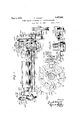
Fig. l is a front elevation-of `amachine parts being omitted; e Fig. k11 is* a detail vsectionV on the line,v
right,` metalend plates which vsupport the The second ratchetmechanism 1s` provided embodying my` invention, yparts being omitlied,
FigfZ is a planfof the samemachine ;v
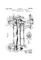
FigQB isran elevation'of the left hand end l of themachinegj i f Y Fig. 4: is an upright section on thefline,
4-4:V for nigga looking t0 the left? i Fig 5 is 'a section on ,the une, 5 5, of Fig. 2, looking in the direction of the arrow; b
Fig. y6 isa rear elevation of the righthand *on fpart of the machine;
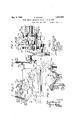
n Fig. 7 is'an elevation of the right hand end ofthemachine; r @1 e l" Fig.l8 is an upright section on the line, 8 8, of Fig. 2,'looking toward the` right; "55
Fig. 9 isa section on the line, '9'-9,` of Fig.
`7', looking inthe direction of the arrow Fig. l1() is a detail section on the' line, 1 0-10, of Fig. 2, looking towardv the left,
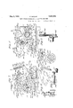
Fig;y 12 is an enlarged view kof, a combined y ratchet-fand camwheel shown rin Fig, 8v; f
l Fig. 13 is a horizontal section on the line, 13--13, of 12;`1 Y
K Figrlt is a perspectiveofa casting comprising bearings for several operating memers;v f Y Fig. 15 is :aho vizontal section onthe line,
`Iii- '15, of Fig. 7
Fig. lshows anothery form of the ratchet and cam wheel. l
` Referringto the drawings, A, A are upl principal [working parts ofthe machine. Each end-plate is `supported onpa horizontal ybase plate, A1. Each base plate, A1,is supported on a leg stand, A2.y At' eachend'o'f the machine, upright bolts,rA3, bindthe end platef'and the base: plate and the. leg stand to each other."
f AB is theroll. for feeding the sheet. In the trade this is termed the lower roll. At each.V f end, said roll hasla journal, B1, resting ini a l 95 bearing, A4, formed in ytheadjacent end Transmission ofpower to the two ratchet Y mechanisms is effected through the' main y 1trans'rtlssion,r shaft, whichis :parallel to ,1100 l I` on a fixed horizontal stub axle, C7, which is supported on the bracket, C8. VThe gear wheel, C3, is'integral witha hub,-C4,`and. a pulley, C5. pulley rotatably surround a fixed horizontal stub axle, C6, whichis supported kon the bracket, C8. A belt (notshown) applied tov the pulley, drives thepulley, whereby motion is transmitted through the gear wheels, C3, C2 andCl, to the shaft,vC, Ithe motion-of the wheel, C1, of the shaft,'G, being clockwise as viewed from the right `hand` end of the machine. i
be-described. Y t v y On lthe left hand'end of the main transmission shaft, C, is fixed an eccentric, D, to
whichis applied an eccentric strap, D1; To
that strap is applied a horizontal arm, D2, the rear end of which-is coupled to the lower end of 'a rocking arm, D3, which is pivoted on a horizontal stub shaft, D4, fixed on the outer or left hand face of the adjacent end plate, A. A block,r D7, slidable'in the slot,
D6, extends lengthwise in the rockingV arm and a pintle, D5, joins the arm, D2, and the .rocking arm, D3'. YA screw, D8.' is threaded through said block and isheld in a bea-ring,
D9, formed in the upper 'end ofthe rocking arm.- On the block,-D7 is ahorizontal stud or'wrist,lD10.'Y Y v An oscillating memberfE,y is heldV loosely VYon the, adjacentneck, B2, lof the roll, B, by `Vmeans of astrap, E1, surrounding said neck.
A link, E2, has its rear end coupled to the stud, D10, on the block,.D7. of the rocking arm. D3. The forward end vof said, link is coupled tothe member,.E, by "means of a horizontal stud. E3. on the right vhand Iside Vof the member. E. 1A pawl. E4, is mounted on a' horizontal stud, E5. vrigid on the left vhand side of the member, E. and is directed rear- Vward. A blade'. E6, is fixed o'nthe free end -4of the pawl and is 'adapted to engage ythe ratchet wheel. E10, whichis fixed on the ad- Vjacentneck'offthe roll, B. A blade spring,
E7is supported on the member, E,fand bears downward on the pawl to yieldingly press the pawl towa-rd'the ratchetwheel. 'A set screw, E8, is threaded on thevpawl in position to bear downward against abracket, E9, seat-V ed on the member, `E. By adjusting this screw on the pawl, the limit of movement'of the pawlbladetoward the ratchet wheel is Saidl gear wheel, hubY andu the main shaft, C, is continuous. Consequently the eccentric, D, is rotated continually and uniformly. Thus the arm, D2, is reciprocated continually for actuating the rocking arm, D3, and the link, E2, the oscillating member, E, and the pawl, E4. The range of oscillation of the member, E, and
Vconsequently the forward throw of the pawl,
nism, will now be described.
This mechanism is in part a duplication of the left khand or first ratchet mechanism above described.
On the main shaft, C, is fixed an eccentric, F, to which is applied an eccentric stra-p, F1, to which is applied a rearward-directed horizontal arm, F2. At the rear of said arm is an uprighty rocking arm, F3, which is pivoted on 0f the machine, the second ratchet mecha-85 The firstratchet mechanism',l that which is 'at the left-,hand end of the machine, will now a stub shaft, F4, extending rotatably` from'Y the 4adjacent end plate, A. A pintle,lF5, serves to couple the rear end of the arm, F2, to the rocking arm, F3. In the upper part of the rocking arm is a slot, F6, parallel toy the length of said' arm. In' said slot is a slidable block, F7. A screw, F8, is placed parallel to said slot and threaded through said block andhas its upper end seated in a bearing, F9. By turning said screw, said block` may be moved along said slot.
An oscillating member, G, has a strap, G1, loosely surrounding the neck, B2, of the roll, Bthe member, G, extending upward from said neck. `A link, G2, joins the oscillating member, G, :and the block, F7, the forward en d of said link being coupled to the member, G, by means of a stud,.G3,'on the member, G, while the rear end of said link is coupled to the block, F7 by means of a stud, F10, on the block, F7. A nut, F11, israpplied to the `outer end o f said stud to retain said link on the stud@ i Y A pawl, G4, has its forward end, G1, on'a stud. G5, on the right hand face of the oscillating member, G. On the other or free end of the pawl is a blade, G6, which is adapted to engage the teeth'of the ratchet wheel, G11. AY blade spring, G7, hasits forward end secured to the member, G, and has itsv rear or free end bea-ring' downward Von the upper face of the pawl, G4, for yield- 'ingly pressing'the pawl downward. An `adj usting screw, G8, extends downward through the body'ofthe pawl.k [A cam lever,'G9, isv
journaled on a stud, G10, seated on the right hand face of the member, G, forward of the stud, G5. Said arm reaches rearward into the path of the adjusting screw, G8. Said screw limits the tilting of the lever, G9, for lowering the forward end of said lever. Said forward end isr so long as to give it weight tending to tilt` said leverand cause it to bear against the screw, G8, with sufficient force to lift the pawl out of engagef ment with the ratchet wheel, G11. But the pressure exertedby the spring,, G7, is to be suflicient to normally overcome this action of the lever, G9, so thatnormally the pawl will act on the ratchet wheel during the rotation of the main shaft, C, and the consequent action of the arms, F2 and F8, and thelink, G2.v Another group of mechanism Yis associated with the cam lever, G9,for periodically depressing said lever to overcome the action of the spring, G7, and cause the lifting of the pawl, G4, out of engagement with the ratchet wheel,1G11. That controlling mechanism will now be described.
An upright triangular rocking plate, H1,
is placed forward of the cam lever, G9, and pivoted to the left hand face of the adjacent end plate, A, on astud, H6, which is fixed on the'end plate. The rear end of the plate, H1,is near the forward arm of the lever, G9. On the right hand face of the rear partof said plate is a wrist, H2, which` extends through said plate and has a shoulder, H3, bearing against said plate. On said wrist is a roller, H. On the outer end of said wrist next to the Vplate is a nut,^H4. When ing lever, H8, located at the left ofthe end of the rocking lever,
plate, A, and pivoted on the bracket, IIS), seated on the base plate, A15 A contracting coiled spring, H10, applied to thenpper Vend is an upright-slot, H11, ywhich, receives a roller, VH13, which is supported on a stud, H12, which has va shoulder,- H14, and has a shank, H15, hearing against the lefthand face of the triangular plate, H1. 'The shank, f H15, rests in a curved slot, H16, formed in the plate, H1, concentric with the stud, H6. On the right hand end'of said shank is a nut, H17. "By driving said nut forward, it and i the shoulder, H14, are'firmly pressed against n the plate, H1, whereby,` the shank, H15, vand the studare held immovably Vin. the curved H8, tends to tilt said lever rearward. In the rocking lever, H8,;
slot, H16. After loosening said nut,fthese parts may be shifted in said slot .to vary the relation between the rocking lever,-`H8, and
the plate,
H1, whereby ythe time4 ofv contact between the roller, H, and the cam lever,
is varied.
Atintervals the rocking leverH8, is forced forward, against the action ofthe springs, 'H10, by means which will now'be described.
At the level of the main shaft, C, a U-form yoke, H18, has one of its arms applied flatwise kto the left handiupright face .of the rocking lever, H8, the open part of the yoke being directed toward the shaft, C. Anaxle, H19, -extends horizontally through the-yoke and supports aroller, H20. Said roller is of sufficient lengthto permit making the part adjacent the lever, H8,cylindrical, and making the other part, H21,tapering or frustroconical. The cylindrical part of this roller is to be engaged by cam'plates, I, `mounted radially on the ratchet wheel, Il. That wheel loosely` surrounds the main transmiss1onshaft, C. v
rIhe rim of said ratchet wheel is thick enough to have radial recessesI2, in the left recesses ratchet teeth, .I4, to serve as dcscribed further on. The recesses, I2, are of uniform size and shape so that any cam plate,
.I, will fit any one of the recesses. `Each cam plate is apertured to receive a cap screw, I3, extending through saidl plate and threaded into .the body of thefwheel, I1, whereby the cam plate visfirmly secured in the recess.
Let it be remembered that the wheel, I1, is loose on the shaft, C. It has ya hub, I5, ex-
'handr'face `and to have at the right of those tended leftward. c On that hub is a circum-` y ferential channel, I6, whichreceives wrists or Y studs, I7, on a shift lever,'I8, which is piv oted by means of a stud, I10, rising from the horizontal bracket, I9, fitted around the stay rod, I11, and securedtosaid rod by means of a set screw,fI12. Thewheel, I1, is to turn clockwise, asviewed from the left of the machine. Each cam plate, I, has acam face,
13, formed to engage the roller, H20, and press it progressively forward and away V from the wheel,'I1. In said face is a depression, I14, adapted to momentarily receive the roller, H20, duringthe downward passing O f the cam plate. Pressing the roller,H20, forward causes forward tilting of the lever,.H8, for tilting the triangular plate, H1, to raise the roller, H, away from the cam lever, G9, to'v permit downward movement of the pawl G4, `to engage the ratchet wheel, G11.
- The ratchet wheel, I1, 1s turned a rela-v i ler pawl,'J1, the latter having at its free end a hook while the former has at its Vfree-end a pointadapted to engage Vthe vratchet teeth, I4, of the wheel, Il. Said. pawls extend rearward from the wheel, I1, and between the arms, 3, rising` from a hub, Arpintlef tively large upper pawlJ, and a similar low- J2, extends ythrough said arms and through said pawls. A contracting spring, S, has its ends connected to the two pawls and yieldingly draws the pawls to the ratchet wheel. The hub, J4, surrounds and is immovably secured to a rock shaft, J5, which rests in bearings, J 6 and J7, formed on the upper part yof the bracket, C8, which Yis seated on the base plate, A1, and supports the gear wheels, C2 and C3. The bearing, J7, is approximately in the plane ofthe main spur gear wheel, C1. At the right of the bearing, J7, a short upkvright rocking arm, J 8,A is fixed on the rock shaft, J5. The rear end of a horizontal pitman, J9, is coupled to the arm, J8, by means of a wrist, J 10, iiXed on said arm. The forwardl end of said pit-man receives a horizontal crank wrist, J 11, on aslide plate, J 12, seated in a channel, J13, in the disc, J15, secured to theright hand face of the main spur gear wheel, C1, by means of cap screws, J 14, eX- tending through slots, J 16, concentric to the a'Xis of said disc and the spur gear wheel,C1. The slide plate, J .12, has a longitudinal slot, J 16. A cap screw, J 17 extends through said slots Vfor binding said plate to said disc. When said screw is loosened, the plate, J l2, may be shifted en dwise for shifting the crank wrist, J11, toward or from the axial line of the wheel, C1, and the main shaft,C, to vary the length ofthethrow of the pitman, J9. The time of the throw of the pitman may be varied by turning the disc,rJ 15, on the wheel, C1, after loosening the screws, J 14.
It will now be seen that the constant rotation ofthe main spur gear wheel, Cl, will vcause the reciprocation of the pitman, J9,
whereby the rock shaft, J 5, andthe arms, J 3, arerocked and the pawls, J Yand J1, are reciprocated, the pawl, J, acting on the ratchet wheel, I1, during forward movement and the pawl, J1, acting on said ratchet wheel during rearward movement. The free ends of Y said pawls `are madewide enough to remain in engagement with theratchet teeth of the wheel, I1, during sidewise movement of that wheel by means of the shift lever, I8,already described.l VThis `same result may be accomplished by making the ratchet teeth, I4, wide enough to remain in engagement with the [pawls during the sidewise shifting of the j ratchet wheel.
When this ratchet wheel has been shifted.
so as to bring the cam blocks or plates, I, into the plane of the cylindrical part of theV roller, H20, the rotation of the cam wheel will cause the cam plates to press said roller and thel yoke, H18, and the lever, H8, outward (forward). But when the cam wheel is shift-eden the shaft, C, so as to bring the cam plates into the'plane of the slanting part, H21, of the roller, H20, the cam platescan pass the roller without making engagement yWith said roller. Under that condition, the
.cam-wheelcan turnindeinitely without tilting the lever, H8, tofree the 'cam lever, G9,
ing lever during one turn of the wheel, I1,
the intervals between said movements being equal. Any number of the cam plates may be thus placedon the wheel, Il, with any desired spaces between them. Thus the occurence of the non-folded parts of the sheet may be varied.
As a substitute for rendering the wheel, I1, inactive by tapering the roller, H20, the ratchet teeth, I4, on -the wheel, I1, maybe made only wide enough t'o come into engage-l ment with the pawls, J and J1, when the wheel is. in working position, the adjacent face of thewheel being smooth to allow the sliding of thepawls during their movements. See Fig. 16. f Y
Since, as above described, the transmission to the pawls, E4 and G4, is from the main shaft, C,it`is to be understood that the pawls move in unison, the pawl, E4, engaging its ratchet wheel at every stroke and the pawl.
son or simultaneously and the pawl, G4,
moves, it follows that the pawl, G4, also: moves faster than lthe pawl, E4, moves.
I claim as my invention, l
l.` In a machine of theV kind described, the combination with a feed roll, anism at one end of said roll for repeatedly turning said roll and a second mechanism at the other end of said roll for at times turning said roll farther than the roll is turned by the first mechanism. j
2. In a machine of the kind described, the combination with a feed roll, of a first mechanism at one end of said roll for repeatedly turning said roll and a second mechanismy at the other end of said roll for at times simulj taneously with the actionof the first mechanism turning said roll farther than the'roll is turned by the first mechanism.
3. In a machine of the kind described, the combination with a feed roll, of a first mechanism at one end of said roll for repeatedly turning said roll and a second mechanism at the other end of said rol-l for at times turning said roll farther than the roll is turned of a first mechbythe first mechanism, the second mechanism Y frequency of the action of said mechanism.
4. In a machine of the kind described, the combination with a feed roll, of a first mechanism for repeatedly partially turning said roll and a second mechanism for at times turning said roll farther than the roll is turned by the first mechanism, said second mechanism including means for varying the distance through which the roll is turned by said mechanism and for varying the frequency of the action of said second mechanism.
5. In a machine of the kind described, the combination with a feed roll, of a rst mechanism for periodically partially turning said roll, and a second mechanism for at times turning the roll farther than the roll is turned by the first mechanism, the second mechanism c including a ratchet wheel, a rocking member, a pawl hinged on the rocking member, a lever supported on the rocking member and adapted to move the pawl out of the range of the ratchet teeth, and mechanism for periodically tilting said lever, whereby the pawl is made to act on the ratchet wheel through some of the movements of the rocking member and does not so act during other movements of the roc-king member.
6. In a machine of the kind described, the combination with a feed roll, of a rst mechanism for periodically partially turning said roll, and a second mechanism for at times turning the roll farther than the roll is turned by the first mechanism, the second mechanism including a ratchet wheel, a rocking member, a pawl hinged kon the rocking member, a lever supported on the rocking member and adapted to move the pawl out of the range of the ratchet teeth, and mechanism for periodically tilting said lever, whereby the pawl is made to act on the ratchet wheel through some of the movements of the rocking member and does not so act during other movements of the rocking member, and a drive shaft in operative relation with said first mechanism and said second mechanism for driving said mechanisms.
7. In a machine of the kind described, the combination with a feed roll, of automatic mechanism for partially turning said roll, said mechanism including a ratchet whe-el and a pawl and automatic means for at regular intervals moving said pawl forward and means including a cam wheel and transmission members between said cam wheel and the pawl for during chosen intervals holding the pawl away from the ratchet wheel and said cam wheel being shiftable into and out of action.
8. In a machine of the kind described, the combination with a feed roll, of a mechanism for partially turning said roll, said mechanism including a ratchet wheel and a pawl and means for at regular intervals moving said kpawl r`forward 'and means includinga cam wheel adapted to bear a plurality of detachable cammembers and :transmission members between said cam wheel and the pawl for during chosen intervals holding the pawl away from the ratchet wheel and said cam wheel being shiftable into and out of action.
9. In a machine of the kind described, the combination with a feed roll, of a ratchet wheel, an oscillating member, means for oscillating said oscillating member, a pawl coupled to said oscillating member in position to normally engage the teeth of said ratchet wheel, means yieldingly pressing the pawl toward said wheel, a member movably supported on said oscillating member in position to be moved to engage and move said pawl away from said wheel, and means for at chosen intervals moving said movably supported member to move said pawl away from said wheel.
10. In a machine of the kind described, the combination with a feed roll, of a ratchet wheel, an oscillating member, means for oscillating said oscillating member, a pawl coupled to said oscillating member in position to normally engage the teeth of said ratchet wheel, means yieldingly pressing the pawl toward said wheel, a member movably supported on said oscillating member in position to be moved to engage and move said pawl away from said wheel, means for adjusting engagement between the pawl and said movably supported member, and means nsI for at chosen intervals moving said movably supported member to move said pawl away from said wheel.-
ll. In a machine of the kind described, the combination with a feed roll, of a ratchet wheel, an oscillating member, means for oscillating saidoscillating member, a pawl coupled tok said oscillating member in position to normally engage the teeth of said ratchet wheel, means yieldingly pressing the pawl toward said wheel, a cam lever supported on said oscillating member in position to be moved to engage and move said pawl away from said wheel, and means for at chosen intervals moving said cam lever to move said pawl away from said wheel.
12. In a machine of the kind described, the combination with a feed roll, of a ratchet wheel, an oscillating member, means for oscillating said oscillating member, a pawl coupled to said oscillating member in posi-y tion to normally engage the teeth of said ratchet wheel,means yieldingly pressing the pawl toward said wheel, a cam lever supported on said oscillating member in position to be moved to engage and move said pawl away from said wheel, means for adjusting engagement between the pawl and said cam lever, and means for at chosen intervals moving laf said cam lever to move said pawl away from said wheel. Y
In testimony whereof I have signed my name, this 4th day of February, in the year one thousand nine hundred and twentyseven.
FRANK MAXANT.
Priority Applications (1)
| Application Number | Priority Date | Filing Date | Title |
|---|---|---|---|
| US167796A US1857028A (en) | 1927-02-12 | 1927-02-12 | Sheet feeding mechanism for plaiting machines |
Applications Claiming Priority (1)
| Application Number | Priority Date | Filing Date | Title |
|---|---|---|---|
| US167796A US1857028A (en) | 1927-02-12 | 1927-02-12 | Sheet feeding mechanism for plaiting machines |
Publications (1)
| Publication Number | Publication Date |
|---|---|
| US1857028A true US1857028A (en) | 1932-05-03 |
Family
ID=22608860
Family Applications (1)
| Application Number | Title | Priority Date | Filing Date |
|---|---|---|---|
| US167796A Expired - Lifetime US1857028A (en) | 1927-02-12 | 1927-02-12 | Sheet feeding mechanism for plaiting machines |
Country Status (1)
| Country | Link |
|---|---|
| US (1) | US1857028A (en) |
-
1927
- 1927-02-12 US US167796A patent/US1857028A/en not_active Expired - Lifetime
Similar Documents
| Publication | Publication Date | Title |
|---|---|---|
| US3954258A (en) | Second fold roller mounting and adjustment means | |
| US2474160A (en) | Ductor roller adjustment and method | |
| US1235805A (en) | Feeding mechanism for webs of paper and the like. | |
| US1857028A (en) | Sheet feeding mechanism for plaiting machines | |
| CN209252573U (en) | A kind of continuously adjustable device of radial distance | |
| US2950677A (en) | Printer-slotters | |
| US2105328A (en) | Reciprocating bed motion for flat bed presses | |
| US932600A (en) | Stencil-printing machine. | |
| US1868383A (en) | Fountain roll feeding means for printing presses | |
| US649392A (en) | Device for applying glue to paper boxes. | |
| JP2597888B2 (en) | Seeding machine | |
| US995524A (en) | Multicolor-printing press. | |
| US1125995A (en) | Printing-press. | |
| US916432A (en) | Moistening mechanism for printing-presses. | |
| US363760A (en) | Inking apparatus for printing-machines | |
| US1858706A (en) | Box machine | |
| US1774499A (en) | Wiping mechanism for plate-printing machines | |
| US989385A (en) | Printing-press. | |
| US2047552A (en) | Paper folding mechanism | |
| US1210156A (en) | Inking mechanism for printing machinery. | |
| US1454439A (en) | Measuring and feeding device | |
| US68471A (en) | Improvement in peinting-presses | |
| US3030883A (en) | Engraver's automatic rotary press | |
| US667772A (en) | Throw-off attachment for printing-presses. | |
| US859837A (en) | Embossing-machine. |