US1856985A - Regenerative repeater for start-stop systems of automatic telegraphy - Google Patents
Regenerative repeater for start-stop systems of automatic telegraphy Download PDFInfo
- Publication number
- US1856985A US1856985A US453008A US45300830A US1856985A US 1856985 A US1856985 A US 1856985A US 453008 A US453008 A US 453008A US 45300830 A US45300830 A US 45300830A US 1856985 A US1856985 A US 1856985A
- Authority
- US
- United States
- Prior art keywords
- relay
- segment
- brush
- distributor
- over
- Prior art date
- Legal status (The legal status is an assumption and is not a legal conclusion. Google has not performed a legal analysis and makes no representation as to the accuracy of the status listed.)
- Expired - Lifetime
Links
Images

Classifications
-
- H—ELECTRICITY
- H04—ELECTRIC COMMUNICATION TECHNIQUE
- H04L—TRANSMISSION OF DIGITAL INFORMATION, e.g. TELEGRAPHIC COMMUNICATION
- H04L25/00—Baseband systems
- H04L25/38—Synchronous or start-stop systems, e.g. for Baudot code
- H04L25/40—Transmitting circuits; Receiving circuits
- H04L25/42—Transmitting circuits; Receiving circuits using mechanical distributors
Definitions
- This invention relates to a start-stop telegraph system and more particularly to regenerative repeaters therefor.
- repeaters may be divided into two general classes, those which provide a stronger impulse on retransmission, and those which perform that function and in addition provide a reshaping of distorted impulses on retransmission. This invention relates to the latter type of repeater.
- the main object of the present invention is to provide a start-stop apparatus employing the regenerative principle of operation.
- Repeat-er stations often function as the originating point of signalling impulses for communication therebetween and either ter minal station. lVhen used as a repeater,
- impulses are received and stored up in'a set of relays at the intermediate or repeater station to be retransmitted as regenerated impulses.
- the transmitting equipment can be substituted for the receiving portion of therepeater apparatus.
- Another object of this inven tion is to provide a regenerative repeater that may be converted into a transmitting'set.
- the receiving mantator brush In order'to' insure synchronism between the transmitting and receiving distributor, the receiving mantator brush must be rotated slightly faster than a the transmitting distributor brush so that 7 the brush at the receiving'end will reach the start segment and beprepared to receive the start impulse when it arrives. It will be obvious that in coming to rest after rotating at a hi h speed, the receiving distributor brush will undergo a certain amount of chatteringv or bouncing Consequently when the start brush vibration isconsiderable, the brush may be thrown completely out of phase with.
- the present invention aims to overcome this" difliculty by .provid-- ing an auxiliary multiple circuit for the start magnet. which circuit is entirely independent of the distributor brush for insuring the .1
- a further object of the presentlinvention is to providemeans for assuring the maintenance of synchronism in a start stop system, r
- Figure Qf is a diagrammatic illustration of the apparatus embodying the invention arranged to operate as a repeater
- Figure 3 is a diagrammatic illustration of the apparatus arranged to operate as a transmitter.
- the motor 31 drive's the main shaft 85 having a worm 36'fixedthereon in mesh with aworm gear be best understood by Referring-to Figure 1 the repeater com prises an'electric' motor 31 for operat ngthe.
- the receiving distributor 32 comprises a brush arm 40 carrying four brushes 41, 42, 43, and 44 which wipe over rings 45, 46, 47, 48, respectively, as the arm 40 rotates.
- Ring 45 comprises a rest-start segment and six code segments.
- Ring 46 is solid, ring 47 comprises three segments and ring 48 comprises four segments.
- the starting and stopping of the rotation of the arm 40 is controlled by a starting magnet 50 having an armature 51, pivoted at52, and, normally held in retracted position by a spring not shown.
- the armature is provided with a stop lug 53 which liesin the path of the arm 40 when the magnet 50 is de-energized and the armature is in retracted position. Energization of the magnet 50 attracts armature 51 so that the stop lug 53 moves out of the path of rotation of the arm 40 and the arm 40 is permitted to start rotating.
- the transmitting distributor 33' comprises a rotatable brush arm 55 carrying two brushes 56 and 57 which wipe over rings 58 and 59 respectively, the former comprising a start segment,"a plurality of code segments and a rest segment, the latter being a solid ring.
- the transmitting distributor is provided with a starting magnet .60 which has an armature 61 pivoted at 62 normally held in retracted position by a spring not shown and provided with a stop lug 63.
- the magnet controls the starting of the transmitting distributor arm 55 in the same manner that the magnet 50 controls the starting of the distributor arm 40.
- the frictional clutch for connecting the brush arms and 55 with the shaft 38 is well known in the art but will be described briefly herein.
- the friction clutch comprises two metal discs 64 and 65 which are secured to the shaft 38. Between the metal discs 64 and 65 are twofriction discs, 66 and 67 made of suitable friction material and arranged between these friction discs is the brush arm 40. As the shaft 38 rotates, the metal discs 64 and 65 rotate therewith. If the arm 40 is free to rotate, the frictional forces acting through the friction discs 66 and 67 will be sufficient to rotate the arm.
- each section comprising a short conducting segment and a portion of insulating material.
- the conducting segments are designated in the drawings by reference numerals 72 to 76, inclusive.
- Cooperating with each of the sections is a pair of brushes. These brushes are designated in the drawings by the reference numerals 77 to 86 inclusive.
- the apparatus comprises in addition to the distributors and the starting magnets, a receiving relay 87 which is responsive to the incoming impulses from the remote station over line L, a starting relay 88 which controls a multiple circuit around the brushes 41 and 42 for insuring the proper operation of the start magnet 50 in a manner to be described hereinafter, a transmitting relay 89 which controls the transmission of the impulses to a ticker or printer or to a remotestation, and a group of six polar relays 90 to 95, inclusive.
- These relays are known in the art as Potts relays, and, as is well known to persons skilledin the art, the armature of such a relay remains operated in whichever position it is thrown.
- This segment is connected over a conductor 104 with one terminal of the winding of start magnet 50, the other terminal of the Winding being connected to negative battery.
- the circuit comprising conductors 100 and 103 constitutes an auxiliary energizingcircuit' for the receiving start magnet 50, as will be described hereinafter.
- the winding of the starting relay. 88 has one of its terminals connected to ground and the other terminal connected over a conductor 105 to segments 13 and 14 of the ring 47.
- brushes 43 and 44 When brushes 43 and 44 are engaged with the segments 13 and 15, respectively, negative battery will be extended over segment 15, brush 44, brush 43, segment 13, conductor 105, winding ofrelay 88 to ground.
- Negative current flowing through the winding of relay 88 operates armature 102 into engagement with contact 101and thereby closing the auxiliary circuit including theconductors 100 and 103.
- the receiving brush 41 initially is resting on the rest-start segment of ring 45.. At this time the brushes 43 and 44 are respectively in engagement with the segments 13 and 15, and the brush 56 of the transmitting distributor is on the rest segment of the ring 58.
- a positive impulse is required. WVhen such impulse is received by relay 87, armature 96 will be, operated into engagement with its contact 97 thus extending positive battery over contact 97, armature 96, c0nductor 99, solid ring 46, brushes 42 and 41, rest-start segment of the ring 45, conductor 104 and through the winding of the receiving start magnet 50 to the negative battery.
- the magnet 50 energizes and removes its armature 51 ( Figure 1) from the path of the brush arm 40, allowing the brush arm to rotate.
- the speed of rotation of the arm is 50 adjusted that as each impulse comprising the code combination representing a character is received on the receiving relay 87, the brush 41 will be wiping over the segment on the ring 45 corresponding to the position of the impulse in the code combination.
- the polar relays 90 to 95, inclusive are energized by positive currents or negative currents depending upon the polarity of the incoming impulses, and the armatures of the polar relays are thrown to the right or left. It is to be noted that when the brush 41 moves off the rest-start segment of ring 45, the primary energizing circuit for the start magnet is broken and the magnet 50 is'deenergized, allowing its an; mature 51 to move into the path of thebrush arm 40 sothat the brush arm will be stopped.
- icircuit is established for the sending start magnet from positive battery over segment 12, brushes 44 and 43,-segment 11, GO11 ductor 107 and through the winding of magnet 60 to ground.
- Magnet 60 energizes and:
- the startsegment on ring 58 is permanently connected to positive battery. Ascordingly, when brush 56 wipes over the start segment on ring 58 a positive impulse will be extended from the start segment over brush 56, brush 57, ring 59, conductor 108 and through the winding ofthe transmitting relay -89. to ground. Positive current flowing through the winding of transmitting relay 89 moves its armature 109 into engagement with contact 110 extending a positive impulse from positive battery over. contact 110, armature 109 and overa conductor 111 to a stock ticker or.
- Vv hen brush 56 wipes over the segment 1 of ring 58, the impulse pre' viously stored in relay will be extended over brushes 56 and 57, ring 59 and conductor 108 to the transmitting relay 89,which in turn will operate its armature in accordance with the polarity of the potential to extend a corresponding impulse over the. conductor 111.
- the impulses previously stored in the polar relays 91 to 95, inclusive, are extended to the transmittingrelay 89. 3
- impulses are being stored in the polar relays 90 to and subsequently transmitted by the transmitting'dis: tributor.
- segment lot ring 45 the first impulse of the code representing the character Y 1s TSCGlVGd.
- the operation of the repeater will now be described, assuming that the character Y is to be repeated.
- the character Y consists of alternate positive and negative impulses.
- the brush 41 is resting on the rest-start segment of ring 45, and the local brush 43 is resting on segment 130i the ring 47 as shown in Figure 2. 'lVith the parts in this position, negative battery is applied to the coils of receiving relay 87 and its armature 96 is in engagement with the contact 98.
- the first impulse to be received isthe start impulse which is of positive polarity.
- the armature 96 of receiving relay 87 will therefore be thrown to the contact 97 extending posi tive battery over: conductor 99, ring 46, brushes 42 and 41, rest-start segment of ring 45, conductor 104 and through the winding of receiving start magnet 50 to negative battery.
- Start magnet 50 is energized releasing the brush arm 40 for rotation.
- Brush arm 40 as it rotates moves the brushes 41, 42, 43 and 44 over the rings 45, 46, 47 and 48, re-
- negative battery will be extended through segments 3 and 5 or" ring 45to the windings of polar relays 92 and 94 and negative battery will be extended to segments 3 and 5 of transmitting ring 58.
- positive battery will be extended through segments 4 and 6 of ring 45 to the windings of polar relays 92 and 94 and positive battery will be extended to segments 4 and 6 of the transmitting ring 58.
- the segments 1 to 6, inclusive, on the receiving ring 45 are short as compared with the segments 1 to 6, inclusive, on the transmittingring 58.
- the timing relation between the rotation ofbrush 41 and the incoming impulses is such that brush 41 will be passing over the short segments on ring 45 as the middle of each impulse is being received on the receiving relay 87.
- This relation is provided to take advantage of the fact that the middle of each impulse will probably be of the right polarity,whereas, the crossover time or change of polarity between impulses is liable to be variable.
- the repeater can be operated to retransmit the impulses as strong, well-shaped impulses.
- the repeater of Figure 2 can be converted into a transmitter by switching out the receiving equipment and switching in a trans mitter and its associated equipment. Any well-known means for performing this switching operation may be employed.
- Figure 3 shows the repeater prepared to operate as a transmitter.
- the equipment comprises a tape c011- trolled transmitter 125, a cut-off relay 126, and the commutator 34 which has already been described in connection with Figure 1.
- the tape controlled transmitter 125 is of the type wherein the contacts carried by the feelers 127 normally, that is, in their unselected condition, engage associated contacts 128 which contacts are all connected to bus bar 129, and when in their selected position engage associated contacts 130 which are all connected bus bar 131.
- Bus bar 129 is connected directly to the brush 81 of commutator and bus bar 131 is connected through winding 132 of cut-oil relay 126 to brush 79 of commutator 34.
- Brush 82 is connected to positive battery and brush 80 is connected to negative battery. Segments 73 and 74 of the commutator are so arranged that they are engaged by their respective brushes simul- Accordingly negative battery will be applied to the bus bar 131 and positive battery will be applied to bus bar 129 at,
- the contactsof the feelers 127 of the tape controlled transmitter 125 are connected to the windings of polar relays90 to inclusive. It will be apparent from this arrangement that when the feelers 127 have been positioned in accordance with perforations in the tape, those feelers which engage contacts 130 on bus'bar 131 will'extend negative battery to the windings of their associated polar relays and those feelers-which engage contacts 128 on bus bar 129, will extend positive battery to the windings of their associated polar relays. Accordingly the arma tures of the polar relays are thrown to the right or left in accordance with the perform tiens in the tape. Y
- the cut-0E relay 126 has in addition to the Winding 132, a winding 133 which is arranged to oppose the efi'ect of the winding 132 but which is ineffective to operate the established for the winding 132 providing one or more of the feelers 127 is in engagement with the contacts'130 on the bus bar 131.
- a winding 133 which is arranged to oppose the efi'ect of the winding 132 but which is ineffective to operate the established for the winding 132 providing one or more of the feelers 127 is in engagement with the contacts'130 on the bus bar 131.
- the circuit will, extend from negative battery, over low resistance ,135, brush80, segment 73, brush 79, winding 132, bus bar 131, uppermost contact 130'and feeler 127 and through the winding of the polar relay 95 to ground.
- Negativecurrent flowing through the winding 132 will operate armature 134 of relay 126 into engagement with the contact 137 thereby extending positive
- a circuit is completed through the segment 72 of the commutator 34 and through the stepping magnet 138, the circuit extending from positive battery over brush 78, segment 72, brush 77 and through the winding of magnet 138 to ground. Positive current flowing through magnet 138 energizes this magnet to step the tape in the transmitter and thus preparing it for the next selection.
- the energizing circuit for the magnet 138 is so timed that it is established after the circuits through segments 7 3'and 74 of the commutator 34 have been opened.
- This winding performs two functions, first, it prevents a start impulse from being transmitted when there is a blank space in the tape and second, applies negative battery to all of the segments of the transmitting ring 58; Both of these functions are performed by the mere switching of the armature 134 of relay 126 into engagement with contact 139. The action of winding 132 will now be described.
- segment 75 will engage brushes 83 and 84 establishing a circuit for the winding 133 of the cut-off relay 126.
- the efi'ect of energization of winding 133 will be to maintain the armature 134 of relay 126 in engagement with its contact 139.
- segments 7 3 and 74 engage their respective brushes so that negative battery will be applied through coil winding 132 to the bus bar 131 and positive battery will be applied to the bus bar 129.
- the magnetic effect of the winding 132 dominates that of winding 133 as above described and succeeds by reason of its later application so that the armature 134 of relay 126 is thrown into engagement with its contact 187.
- the segment 7 6 will engage the brushes 85 and 86 energizing the sending start magnet 60 which releases the brush arm 55 for rotation.
- the brush 56 wipes over the start segment transmittin g a positive impulse over the conductor 111 which starts the remote receiving apparatus into operation.
- the brush 56 then wipes over the segments 1 to 6, inclusive, in succession transmitting impulses over the segments to'the conductor 111, and finally the brush 56 will come to rest on the rest segment of the,
- transmitters of the tape controlled type for purposes of illustration but it is evident that other types of transmitters may be employed, such for instance as storing transmitters.
- a receiving distributor means for controlling the starting of said distributor. plurality of relays controlled by. said distributor. a transmitting distributor controlled by said relays ano a local distributor for controlling the starting or" the receiving distributor and the transmitting distributor. V a
- a re in a start-stop telegraph system, a re DC distributor, a pluralityjof relays controlled by said receiving distributor, a transmitting distributor controlled by said relays and a local distributor controlling the phase relation between the receiving distributor and the transmitting distributor.
- a receiving distributor Ina start-stop telegraph system, a receiving distributor, a magnet for controlling the starting of said distributor, said magnet being controlled by the distributor, auxiliary means for controlling said magnet and a local distributor controlling said auxiliary means.
- a receiving relay responsive to incoming impulses, a receiving distributor for distributing the impulses received by said relay, a plurality of polar relays controlled by said receiving distributor for repeating the impulses, a transmitting distributor for distributing the impulses repeated by said polar relays, an d a transmitting relay responsive to the impulses distributed by the transmitting distributor for repeating the same to a remote station.
- a receiving relay responsive toincoming impulses, aplurality of polar relays, means controlled by saidreceiving relay for distributing the incoming impulses to the polar re lays, a transmit-ting relay for transmitting the impulses to a remote point and a trans mitting distributor for distributing the impulses received by said.
- polar relays to said transmitting relay.
- a rotary distributor for controlling the starting of said distributor, an energizing cir-' cuit for said magnet controlled by the distributor and an auxiliary energizing circuit for said magnet, said auxiliary circuit being independent or said distributor.
- a rotary distributor for controlling the starting of saiddistributor, an energizing circuitfor said magnet-controlled by the distributor, an auxiliary energizing circuit for said magnet, said auxiliary circuit being independent of said distributor, a relay for controlling said auxiliary circuit and means operating in synchronism with said distributor for controlling said relay.
- a tape controlled transmitter In a start-stop telegraph system, a tape controlled transmitter, a plurality of polar relays controlled by said transmitter, a transmitting distributor and continuously operatsequence control means for controlling the operation of said tape controlled transmitter and said transmitting distributor.
- a start-stop telegraph system a plurality of tape controlled elements, a plurality of relays controlled by said elements, means itio iis
- a start-stop telegraph system a plurality of tape cont-rolled elements adapted to be positioned in accordance with perforations in a tape, a distributor for transmitting impulses over a line in accordance with the positions of the tape controlled elements, a continuously rotating commutator, means controlled by said commutator for extending a start impulse to the start segment of the distributor and additional means controlled by the commutator for preventing the transmission of a start impulse by said distributor when the tape-controlled elements are all in predetermined position.
- a start-stop telegraph system a plurality of tape controlled elements adapted to occupy one of two positions in accordance with perforations in a tape, a plurality of polar relays adapted to be operated in accordance with the positions of said tape controlled elements, a distributor for transmitting positive or negative impulses in accordance with the operation of the polar relays,
- a continuously rotating commutator said commutator controlling the starting of said distributor, a cut-oil relay having a plurality of windings controlled by said commutator, one of said windings controlling the transmission of a start impulse by the distributor and the other of said windings operating to prevent the transmission of a start impulse by the distributor when the said tape controlled elements occupy predetermined positions.
- a start-stop telegraph transmitter a plurality of tape controlled elements adapted to occupy one of two positionsin accordance with perforations in a tape, a rotary distributor for transmitting impulses over a line in accordance with the positions of the tape controlled elements, said distributor comprising a rest segment, a start segment, and a plurality of code segments, means for applying a predetermined potential to the start segment of the distributor and means for applying a potential of opposite polarity to all of the segments of the distributor under a predetermined condition.
- a start-stop telegraph system a plurality of tape-controlled elements adapted to occupy oneof two positions in accordance with perforations in a tape, a distributorfor transmitting impulses over a line in accordance with the positions occupied by the tape controlled elements, said distributor comprising a start se ment, a plurality of code segments and a rest segment, an electric relay for applying a start impulse condition to the starting segment under predetermined conditions in the tape and for applying a difi'erent impulse condition to the start segment under other predetermined conditions in the tape.
- a plurality of tape controlled elements adapted to occupy one of two positions in accordance with perforations in a tape
- a distributor for transmitting impulses over a line in accordance with the positions occupied by the tape controlled elements, said distributor comprising a start segment, a plurality of code segments and a rest segment, an electric relay for applying a start impulse to the start segment under predetermined conditions in the tape and for applying a difierent impulse to the start segment under predetermined other conditions in the tape, and continuously rotating means for controlling said relay.
- a plurality of tape controlled elements adapted to occupy one of two positions in accordance with perforations in a tape
- a distributor for transmitting impulses over a line in accordance with the positions occupied by the tape controlled elements, said distributor comprising a start segment, a plurality of code segments and a rest segment, an electric relay for applying a start impulse to the start segment under predetermined conditions in the tape and for applying a diiferent impulse to the start segment under predetermined other conditions in the tape and means for timing the operation'of the distributor and the relay and for controlling the stepping of p the tape.
- a transmitter In a start-stop telegraph system, a transmitter, a plurilaty of relays controlled by said transmitter, a distributor for transmitting positive or'negative impulses in accordance with the operation of said relays, and continuously operating sequence control means for controlling the operation of said transmitter and said distributor.
- a start-stop telegraph system a plurality of contacts'adapted to be positioned in accordance with a predetermined coding, a plurality of relays controlled by the position of said contacts, means for transmitting a code combination of impulses in accordance with the operation of said relays, and a continuously operating commutator for controllin g the starting of said last mentioned means.
- a transmitter having a plurality of contacts adapted to be positioned in accordance to a predetermined coding, a plurality of relays controlled by the position of said transmitter contacts, a transmitting distributor, and con tinuously operating sequence control means for controlling the operation of said transmitter and said distributor.
- a plurality of contacts adapted to be positioned in accordance with a predetermined coding
- said distributor comprising a start segment, a plurality of code segments and a rest segment, a relay for applying a start'impulse to said start segment under predetermined positioning of said contacts and for applying a difierent'impulse to said start segment under other predetermined positioning of said contacts.
Landscapes
- Engineering & Computer Science (AREA)
- Computer Networks & Wireless Communication (AREA)
- Signal Processing (AREA)
- Dc Machiner (AREA)
Description
May 3, 1932. R. F. DIRKES ET AL 1,355,935
STQP SYSTEMS OF AUTOMATIC TELEGRAPHY Filed May 16, 1930 REGENERATIVE'REPEATER FOR START:-
5 Sheets-Sheet 1; f
M n I 3 NM. on mm w w May 3, 1932. R. F. DIRKES ETAL REGENERATIVE REEEAI'ER FOR START-STOP SYSTEMS OF AUTOMATIC TELEGRAPH! Filed May 16, 1950 3 Sheets-Sheet 2 -& r u "3 x: k m 5* l S i n5 wfim 8% x L JS 0 e 5 w Q 5% Q mentors;
J27. ke-s cZZYfAnderaon, :5:
y 9 R. F. DIRKES ETAL 1,356,985
REGENERATIVB REPEATER FOR START-STOP SYSTEMS OF AUTOMATIC TELEGRAPH! Filed ua Te, 19:50 5 Sheets-Sheet 3 inventors.-
,Z I. flirkes ,A nderson, Jr
Gttomeg Patented May 3, 1932 iJNrrsu stares PATENT OFFICE ROBERT F. DIRKES, OF JAMAICA, NEW YORK, AND JAMES N. ANDERSON, 53., OF NORTH;
PLAINFIELD, NEW JERSEY, ,ASSIGNORS TO THE WESTERN UNION TELEGRAIH COM- PANY, OF YORK, N. Y., CORPORATION OF NEW YORK REGENERATIVE BEIEA'IER FOR START-STOP SYSTEMS OF AUTOMATIC TELEGRAPHY Application filed; May 1 9 Serial No.
This invention relates to a start-stop telegraph system and more particularly to regenerative repeaters therefor.
As is well known to those skilled in the art of telegraphy, repeaters may be divided into two general classes, those which provide a stronger impulse on retransmission, and those which perform that function and in addition provide a reshaping of distorted impulses on retransmission. This invention relates to the latter type of repeater.
The regenerative principle of operation has been applied extensively to multiplex telegraph systems but has never been applied to start-stop telegraph systems. 7
Accordingly the main object of the present invention is to provide a start-stop apparatus employing the regenerative principle of operation.
Repeat-er stations often function as the originating point of signalling impulses for communication therebetween and either ter minal station. lVhen used as a repeater,
. impulses are received and stored up in'a set of relays at the intermediate or repeater station to be retransmitted as regenerated impulses. By means of a switching arrangement, the transmitting equipment can be substituted for the receiving portion of therepeater apparatus.
Accordingly, another object of this inven tion is to providea regenerative repeater that may be converted into a transmitting'set.
In start-stop systems, difiiculty has been experienced in maintaining synchronismbe' tween the receiving distributor and thetransmitting distributor operating at a high speed due to vibration of the brushes at the stop segments when completing the circuit for the'starting magnet. As is wel'l'known, the circuit for the starting magnet extends through the brushes of the receiving distribu:
tor and start segment. In order'to' insure synchronism between the transmitting and receiving distributor, the receiving mantator brush must be rotated slightly faster than a the transmitting distributor brush so that 7 the brush at the receiving'end will reach the start segment and beprepared to receive the start impulse when it arrives. It will be obvious that in coming to rest after rotating at a hi h speed, the receiving distributor brush will undergo a certain amount of chatteringv or bouncing Consequently when the start brush vibration isconsiderable, the brush may be thrown completely out of phase with.
the incoming signal. The present invention aims to overcome this" difliculty by .provid-- ing an auxiliary multiple circuit for the start magnet. which circuit is entirely independent of the distributor brush for insuring the .1
positive energiz'ation of the starting magnet when the start impulseis received. a p
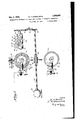
A further object of the presentlinvention, therefore, is to providemeans for assuring the maintenance of synchronism in a start stop system, r The invention-may reference to the following description-in .connection with the accompanying drawings in which r I Figurel is an elevational view showing the distributors and'c'ommutator' and the power drive therefor, I Y
Figure Qfis a diagrammatic illustration of the apparatus embodying the invention arranged to operate as a repeater,- and Figure 3 is a diagrammatic illustration of the apparatus arranged to operate as a transmitter. I
receiving distributor S2, transmitting dis tributor 38'and communtator'34 The motor 31:drive's the main shaft 85 having a worm 36'fixedthereon in mesh with aworm gear be best understood by Referring-to Figure 1 the repeater com prises an'electric' motor 31 for operat ngthe.
37 carried on shaft 38. Connected to the shaft 38 through friction clutches to be described hereinafter are the receiving distributor 32 and transmitting distributor 33. The receiving distributor 32 comprises a brush arm 40 carrying four brushes 41, 42, 43, and 44 which wipe over rings 45, 46, 47, 48, respectively, as the arm 40 rotates. Ring 45 comprises a rest-start segment and six code segments. Ring 46 is solid, ring 47 comprises three segments and ring 48 comprises four segments. The starting and stopping of the rotation of the arm 40 is controlled by a starting magnet 50 having an armature 51, pivoted at52, and, normally held in retracted position by a spring not shown. The armature is provided with a stop lug 53 which liesin the path of the arm 40 when the magnet 50 is de-energized and the armature is in retracted position. Energization of the magnet 50 attracts armature 51 so that the stop lug 53 moves out of the path of rotation of the arm 40 and the arm 40 is permitted to start rotating.
The transmitting distributor 33' comprises a rotatable brush arm 55 carrying two brushes 56 and 57 which wipe over rings 58 and 59 respectively, the former comprising a start segment,"a plurality of code segments and a rest segment, the latter being a solid ring. As in the case of the receiving distributor, the transmitting distributor is provided with a starting magnet .60 which has an armature 61 pivoted at 62 normally held in retracted position by a spring not shown and provided with a stop lug 63. The magnet controls the starting of the transmitting distributor arm 55 in the same manner that the magnet 50 controls the starting of the distributor arm 40. y
The frictional clutch for connecting the brush arms and 55 with the shaft 38 is well known in the art but will be described briefly herein. The friction clutch comprises two metal discs 64 and 65 which are secured to the shaft 38. Between the metal discs 64 and 65 are twofriction discs, 66 and 67 made of suitable friction material and arranged between these friction discs is the brush arm 40. As the shaft 38 rotates, the metal discs 64 and 65 rotate therewith. If the arm 40 is free to rotate, the frictional forces acting through the friction discs 66 and 67 will be sufficient to rotate the arm. If the magnet 50 is de-energized the lug 53 of armature 51 willprevent the rotation of'brush arm 40 but the friction clutch will be continuously operating ready to rotate the arm 40 as soon as'it is released by energization of magnet 50. Geared to the main drive shaft 35,
other and each section comprising a short conducting segment and a portion of insulating material. The conducting segments are designated in the drawings by reference numerals 72 to 76, inclusive. Cooperating with each of the sections is a pair of brushes. These brushes are designated in the drawings by the reference numerals 77 to 86 inclusive.
The arrangement of the apparatus for op eration as a regenerative repeater is shown in Figure 2 in which the distributor rings have been shown developed for the sake of clearness. As shown, the apparatus comprises in addition to the distributors and the starting magnets, a receiving relay 87 which is responsive to the incoming impulses from the remote station over line L, a starting relay 88 which controls a multiple circuit around the brushes 41 and 42 for insuring the proper operation of the start magnet 50 in a manner to be described hereinafter, a transmitting relay 89 which controls the transmission of the impulses to a ticker or printer or to a remotestation, and a group of six polar relays 90 to 95, inclusive. These relays are known in the art as Potts relays, and, as is well known to persons skilledin the art, the armature of such a relay remains operated in whichever position it is thrown.
. As impulses are received over the signalling line from the remote station by the receiving relay 87, its armature 96 vibrates between contacts 97 and 98. Contact 97 is connected to positive battery and contact 98 is connected to negative battery. The armature 96 is connected over a conductor 99 to the solid ring 46 of the receiving distributor 32. Thus the position of the armature 96 of relay 87 determines the polarity that is applied to the ring 46. Armature 96 of the relay 87 is connected over a conductor 100 to the contact 101 of the relay 88, and the armature 102 of the relay 88 isconnected over a conductor 103 with the start segment of ring 45. This segment is connected over a conductor 104 with one terminal of the winding of start magnet 50, the other terminal of the Winding being connected to negative battery. When the armature 102 of the starting relay 88 is in engagement with contact 101, the circuit comprising conductors 100 and 103 constitutes an auxiliary energizingcircuit' for the receiving start magnet 50, as will be described hereinafter.
The winding of the starting relay. 88 has one of its terminals connected to ground and the other terminal connected over a conductor 105 to segments 13 and 14 of the ring 47. When brushes 43 and 44 are engaged with the segments 13 and 15, respectively, negative battery will be extended over segment 15, brush 44, brush 43, segment 13, conductor 105, winding ofrelay 88 to ground. Negative current flowing through the winding of relay 88 operates armature 102 into engagement with contact 101and thereby closing the auxiliary circuit including theconductors 100 and 103.
lVhen the brush 44 moves off the segment 15 a circuit is established from positive battery over segment 16, brushes 44 and43, segment 13, conductor 105, and winding of relay 88 to ground. Positive current flowing through the winding of relay 88, operates armature 102 into engagement with contact 106 thereby breaking the auxiliary circuit.
The receiving brush 41 initially is resting on the rest-start segment of ring 45.. At this time the brushes 43 and 44 are respectively in engagement with the segments 13 and 15, and the brush 56 of the transmitting distributor is on the rest segment of the ring 58. To start the apparatus a positive impulse is required. WVhen such impulse is received by relay 87, armature 96 will be, operated into engagement with its contact 97 thus extending positive battery over contact 97, armature 96, c0nductor 99, solid ring 46, brushes 42 and 41, rest-start segment of the ring 45, conductor 104 and through the winding of the receiving start magnet 50 to the negative battery. The magnet 50 energizes and removes its armature 51 (Figure 1) from the path of the brush arm 40, allowing the brush arm to rotate. The speed of rotation of the arm is 50 adjusted that as each impulse comprising the code combination representing a character is received on the receiving relay 87, the brush 41 will be wiping over the segment on the ring 45 corresponding to the position of the impulse in the code combination.
As the brush 41 wipes over the succeeding isegments 1 to 6, inclusive, the polar relays 90 to 95, inclusive, are energized by positive currents or negative currents depending upon the polarity of the incoming impulses, and the armatures of the polar relays are thrown to the right or left. It is to be noted that when the brush 41 moves off the rest-start segment of ring 45, the primary energizing circuit for the start magnet is broken and the magnet 50 is'deenergized, allowing its an; mature 51 to move into the path of thebrush arm 40 sothat the brush arm will be stopped.
ing through the winding of relay 88 moves its armature 102 into engagement with contact 106 thereby breaking the auxiliary circuit for magnet 50. hen the brushes 43 and 44wipe over the segments 11 and 12, respectively, a
icircuit is established for the sending start magnet from positive battery over segment 12, brushes 44 and 43,-segment 11, GO11 ductor 107 and through the winding of magnet 60 to ground. Magnet 60 energizes and:
moves its armature 61, (Figurel) outv ofthe.
when brush4l wiped over segment 1. This provides the necessary overlap.
The startsegment on ring 58is permanently connected to positive battery. Ascordingly, when brush 56 wipes over the start segment on ring 58 a positive impulse will be extended from the start segment over brush 56, brush 57, ring 59, conductor 108 and through the winding ofthe transmitting relay -89. to ground. Positive current flowing through the winding of transmitting relay 89 moves its armature 109 into engagement with contact 110 extending a positive impulse from positive battery over. contact 110, armature 109 and overa conductor 111 to a stock ticker or. printer, Vv hen brush 56 wipes over the segment 1 of ring 58, the impulse pre' viously stored in relay will be extended over brushes 56 and 57, ring 59 and conductor 108 to the transmitting relay 89,which in turn will operate its armature in accordance with the polarity of the potential to extend a corresponding impulse over the. conductor 111. In a similar manner, as the brush 56 wipes over the segments 2, 3, 4, 5 and 6, the impulses previously stored in the polar relays, 91 to 95, inclusive, are extended to the transmittingrelay 89. 3 There is thus provided an overlap whereby impulses are being stored in the polar relays 90 to and subsequently transmitted by the transmitting'dis: tributor. I i s 3 The restsegment of the ring 58 is permanently connected to negative battery. Ac cordingly, when the brush 56reaches the rest segment a negative impulse will be transmitted over the conductor 108 and through the transmission relay 89 and over the line 111.
Itwill be. noted thatthe rest segment of the ring 58 is shorter than'the other segments in ring 58. The purpose of this proricvision is toassure the stopping of the brush.
56 each time onthe rest segment and thereby assuringthestarting of the brushes in a positive manner by actuation of the starting magnet 60. It is understood that the combined time of movement and rest of the brush 56 onthe rest segment is the same as the time required in the movement of the brush 56' made for an eight-unit code, it is of course,
obvious that the principle herein described embodiment of the invention lllustrated, provision has been spectively.
may be applied to any of the accepted forms of start-stop telegraphy. The eight units for one character combination are as follows: start, selection 1, selection 2, selection 3, selection4, selection 5, selection 6 and rest.
The operation of the repeater will now be described, assuming that the character Y is to be repeated. The character Y consists of alternate positive and negative impulses. The brush 41 is resting on the rest-start segment of ring 45, and the local brush 43 is resting on segment 130i the ring 47 as shown in Figure 2. 'lVith the parts in this position, negative battery is applied to the coils of receiving relay 87 and its armature 96 is in engagement with the contact 98. The first impulse to be received isthe start impulse which is of positive polarity. The armature 96 of receiving relay 87 will therefore be thrown to the contact 97 extending posi tive battery over: conductor 99, ring 46, brushes 42 and 41, rest-start segment of ring 45, conductor 104 and through the winding of receiving start magnet 50 to negative battery. Start magnet 50 is energized releasing the brush arm 40 for rotation. Brush arm 40 as it rotates moves the brushes 41, 42, 43 and 44 over the rings 45, 46, 47 and 48, re-
As the brush 41 wipes over the by the relay 87. This impulse is negative and moves armature 96 of relay 87 into engagement with contact 98 extending negative battery over contact 98, armature'96, conductor 99, ring 46, brush 42, brush 41, segment 1 and through the winding of polar relay 90 to ground. Negative current flowing through the winding of polar relay 90 moves its armature into engagement with contact 115 thereby extending negative battery from contact 115 over the armature of polar relay 90 to segment 1 of the transmitting ring 58.
When the brush 41 wipes over the segment 2 of ring 45 the second impulse in the code combination representing the character Y is received by relay 87. This second impulse is positive and energizes the receiving relay 87 to move its armature 96 into engagement with contact 97 extending positive battery from contact 97 over armature 96, conductor 99, ring 46, brush 42, brush 41, segment 2, winding of polar relay 91 to ground. Positive current flowing through winding of polar relay 91 causes its armature to be thrown to the left into engagement with contact 116, extending positive battery from contact 116 over the armature of relay 91 to segment 2 of the transmitter ring 58. 'In a similar manner negative battery will be extended through segments 3 and 5 or" ring 45to the windings of polar relays 92 and 94 and negative battery will be extended to segments 3 and 5 of transmitting ring 58. Also, positive" battery will be extended through segments 4 and 6 of ring 45 to the windings of polar relays 92 and 94 and positive battery will be extended to segments 4 and 6 of the transmitting ring 58.
When the brushes 43 and 44 wipe over the segments 11 and'12, respectively, positive battery is extended over these brushes and segments and over wire 107 to the transmitting start magnet 60, energizing this magnet to release the brush arm 55 of the transmitting distributor. Inasmuch as the arm 55 of the transmitting distributor starts rotating later in the cycle than the start of brush arm 40, sufiicient time is provided for operation of each polar relay 90, 91, etc. before retransmission of the impulse stored up by said relay. As the brush 56 rotates, it comes first into engagement with the start segment on ring 58, extending positive battery, which is. permanently connected to the start segment,
over brush 56. brush 57, ring 59, conductor 108 and through the winding of transmitting relay 89, operating this relay to repeat apositive start impulse over the conductor 111 leading to the local ticker or printer or to remote apparatus. The brush 56 then moves onto the segment 1 and as it wipes over the segment 1, a negative impulse is extended from negative battery over contact 115 of polar relay 90, and over the armature of relay 90, segment 1 of ring 58, brush 56, brush 57, ring 59, conductor 108 and through the winding of transmitting relay 89 to ground. Negative current flowing through winding of relay 89 operates the armature 109 into en-' gagement'with contact 112 extending a negative impulse over the line 111.
' Similarly, as. the brush 56 wipes over the segments 2 to 6, inclusive, circuits previously prepared bythe polar relays 91 to 95, inclusive, are. completed, and impulses are transmitted through the winding of relay 89 and'repeated thereby over the line 111, the polarityof these impulses depending upon taneously.
the positions of the armatures of the polar relays. The brush 56 then arrives on the rest segment of ring 58 and is stopped thereon due to the engagementof the brush arm by the armature of magnet 60. During the interval when brush 56 is in engagement with the rest segment, negative battery, which is permanently connected to the rest segment, is extended over the brush 56, brush 57, ring 59, conductor 108 and through the winding of the transmitting relay 89 and repeated by this relay over line 111.
It will be noted that in the apparatus of Figure 2, the segments 1 to 6, inclusive, on the receiving ring 45 are short as compared with the segments 1 to 6, inclusive, on the transmittingring 58. The timing relation between the rotation ofbrush 41 and the incoming impulses is such that brush 41 will be passing over the short segments on ring 45 as the middle of each impulse is being received on the receiving relay 87. This relation is provided to take advantage of the fact that the middle of each impulse will probably be of the right polarity,whereas, the crossover time or change of polarity between impulses is liable to be variable. Thus, as long as thereiis enough left of each impulse to operate receiving relay 87 and cause its armature to remain in engagement with one of its cont-acts long enough for the receiving brush 41 to pass over the receiving segment'corresponding to that impulse, the repeater can be operated to retransmit the impulses as strong, well-shaped impulses.
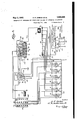
The repeater of Figure 2 can be converted into a transmitter by switching out the receiving equipment and switching in a trans mitter and its associated equipment. Any well-known means for performing this switching operation may be employed. Figure 3 shows the repeater prepared to operate as a transmitter. In place of the receiving relay 87, start relay 88 and the receiving distribntor, the equipmentcomprises a tape c011- trolled transmitter 125, a cut-off relay 126, and the commutator 34 which has already been described in connection with Figure 1.
The tape controlled transmitter 125 is of the type wherein the contacts carried by the feelers 127 normally, that is, in their unselected condition, engage associated contacts 128 which contacts are all connected to bus bar 129, and when in their selected position engage associated contacts 130 which are all connected bus bar 131. Bus bar 129 is connected directly to the brush 81 of commutator and bus bar 131 is connected through winding 132 of cut-oil relay 126 to brush 79 of commutator 34. Brush 82 is connected to positive battery and brush 80 is connected to negative battery. Segments 73 and 74 of the commutator are so arranged that they are engaged by their respective brushes simul- Accordingly negative battery will be applied to the bus bar 131 and positive battery will be applied to bus bar 129 at,
the same time. I
The contactsof the feelers 127 of the tape controlled transmitter 125 are connected to the windings of polar relays90 to inclusive. It will be apparent from this arrangement that when the feelers 127 have been positioned in accordance with perforations in the tape, those feelers which engage contacts 130 on bus'bar 131 will'extend negative battery to the windings of their associated polar relays and those feelers-which engage contacts 128 on bus bar 129, will extend positive battery to the windings of their associated polar relays. Accordingly the arma tures of the polar relays are thrown to the right or left in accordance with the perform tiens in the tape. Y
The cut-0E relay 126 has in addition to the Winding 132, a winding 133 which is arranged to oppose the efi'ect of the winding 132 but which is ineffective to operate the established for the winding 132 providing one or more of the feelers 127 is in engagement with the contacts'130 on the bus bar 131. Assuming that the uppermost feeler127 is in engagementwith itsassociated contact 130 on busbar 131, when segment 73 engages brushes 79 and 80, the circuit will, extend from negative battery, over low resistance ,135, brush80, segment 73, brush 79, winding 132, bus bar 131, uppermost contact 130'and feeler 127 and through the winding of the polar relay 95 to ground. Negativecurrent flowing through the winding 132 will operate armature 134 of relay 126 into engagement with the contact 137 thereby extending positive battery over contact 137 and armature 134 to start segment'on'ring 58.
When segment 76 engages the brushes 85 and 86, an energizing circuit is established for the sending start magnet 60, this circuit extending from positive battery over the brush 86, segment 76, brush 85, conductor 107 and through the winding of magnet 60 to ground. As will be evident from Figure 3, the position of the segment 76 on the 00111 mutator is such that this circuit is established a short time after the circuits through segments 73 and 74 are established. Energization of start magnet 60 releases the brush arm 55 in the manner already described, and,
as the brush arm rotates, the circuits pre-' 7 pared by thepolar relays 90 to 95,inclusive, arecompleted and impulses transmitted in sequence to transmitting relay 89 as described in connection with Figure 2. Since the brush 56 was initially resting on the rest segment, as in the previous case, the start impulse will be the first impulse to be transmitted and so on through the other impulses of the complete character terminating on the rest segment.
After a selection has been made in the tape controlled transmitter 125 and stored up in the bank of polar relays 90 to 95, inclusive, it
is necessary to step the perforated tape in the transmitter 125 and prepare it for the next selection. To this end a circuit is completed through the segment 72 of the commutator 34 and through the stepping magnet 138, the circuit extending from positive battery over brush 78, segment 72, brush 77 and through the winding of magnet 138 to ground. Positive current flowing through magnet 138 energizes this magnet to step the tape in the transmitter and thus preparing it for the next selection. The energizing circuit for the magnet 138 is so timed that it is established after the circuits through segments 7 3'and 74 of the commutator 34 have been opened.
I As previously described in connection with Figure 2, when the brush 56 wipes over the start segment on ring 58, a positive impulse is transmitted over the line 111 to a printer or to remote receiving apparatus. To obtain this positive impulse the armature 134 of the cut-off relay 126 must be in engagement with the contact 137 of the relay 126. This engagement is effected when winding 132 of the relay 126 is energized but in order to energize winding 132 at least one feeler 127 must be in engagementwith its associated contact on bus bar 131. It follows, therefore, that if a particular code combination does not include marking impulses, as in the case where a blank space occurs in the tape, there will be no feelers in engagement with contacts on bus bar 131, winding 132, will be de-energized, armature 134 will be in engagement with contact 139 and a negative impulse will be transmitted over the start segment through the winding of relay 89 which will repeat a negative impulse over the line 111. This negative impulse will not start the apparatus at the receiving end, but the first positive impulse transmitted over the line 111 will start that apparatus. Obviously then the apparatus at the receiving end will be out of phase with the apparatus at the transmitting end. To prevent this undesirable resub the winding 133 and its circuit including the segment 75 on the commutator are provided. This winding performs two functions, first, it prevents a start impulse from being transmitted when there is a blank space in the tape and second, applies negative battery to all of the segments of the transmitting ring 58; Both of these functions are performed by the mere switching of the armature 134 of relay 126 into engagement with contact 139. The action of winding 132 will now be described.
When a blank space occurs in the tape all of the feelers 127 are in engagement with contacts 128 of bus bar 129 and the circuit which extends from negative battery, through low resistance 135, brush 80, segment 73, brush 79 and through winding 132 to bus bar 131, is incomplete, so that winding132 remains de-energized. When the segment 75 engages the brushes'83 and 84, an energizing circuit is established for the winding 133 of the relay 126. This circuit extends from positive battery over brush 84, segment 75, brush 83 and through the winding 133 to ground. Positive current flowing through the winding 133 of the cut-off relay 126 causes the armature 134 thereof to be thrown into engagement with contact 139.
Engagement of armature 134 with contact 139 extends negative battery over contact 139 and armature 134 to the left-hand contacts of polar relays 90 to 95, inclusive, and also to the start segment on the transmitting ring 58. Consequently when the brush arm 55 is released, and brush 56 operates over the transmitting ring 58, every impulse transmitted over the line 111 will be negative. Since a positive impulse is required to start the apparatus at the receiving end the said apparatus will be prevented from starting.
In the following description of the operation of the embodiment shown in Figure 3, it will be assumed that the character Y is to be transmitted and that preceding the character Y there is a blank space in the tape. Accordingly the armature 134 of, cut-oil relay 126 is on its right-hand contact 139 and as the segment 72 of the commutator 34 moves into engagement with brushes 77 and 78 the stepping magnet 138 is energized and operates the tape-stepping mechanism to step the tape. Feelers 1, 3 and 5 will be selected and will move into engagement with contacts on the bus bar 131. Feelers 2, 4 and 6 will be unselected and will remain inengagement with contacts on bus bar 129. As the commutator 34 rotates, segment 75 will engage brushes 83 and 84 establishing a circuit for the winding 133 of the cut-off relay 126. The efi'ect of energization of winding 133 will be to maintain the armature 134 of relay 126 in engagement with its contact 139. Immediately thereafter segments 7 3 and 74 engage their respective brushes so that negative battery will be applied through coil winding 132 to the bus bar 131 and positive battery will be applied to the bus bar 129. The magnetic effect of the winding 132 dominates that of winding 133 as above described and succeeds by reason of its later application so that the armature 134 of relay 126 is thrown into engagement with its contact 187. This applies positive battery to the left-hand contacts of the polar relays to 95, inclusive, and also to the start segment'on ring 58. The windings of polar relays 90, 92 and 94 will be energized by negative current from bus bar 131 and the armatures of these relays will be thrown into engagement with the right-hand contacts. The windings of relays 91, 93 and 95 will be energized by positive current from bus bar-129 and the armatures of these relays will be thrown into engagement with left-hand contacts. Thus, the selection of the character Y is stored in the polar relays 90 to 95, inclusive.
As the connnutator 34 rotates, the segment 7 6 will engage the brushes 85 and 86 energizing the sending start magnet 60 which releases the brush arm 55 for rotation. The brush 56 wipes over the start segment transmittin g a positive impulse over the conductor 111 which starts the remote receiving apparatus into operation. The brush 56 then wipes over the segments 1 to 6, inclusive, in succession transmitting impulses over the segments to'the conductor 111, and finally the brush 56 will come to rest on the rest segment of the,
We have referred in the above description to a transmitter of the tape controlled type for purposes of illustration but it is evident that other types of transmitters may be employed, such for instance as storing transmitters.
1. In a start-stop telegraph system,-a'receivingdistributor, means responsive to incoming impulses tor starting said distributor into operation, a local distributor 'and means controlled by said local distributoroperating as an auxiliary to said starting means for con trolling the starting of the receiving distributor. I
2. In a start-stop telegraph system, a receiving distributor, means for controlling the starting of said distributor. plurality of relays controlled by. said distributor. a transmitting distributor controlled by said relays ano a local distributor for controlling the starting or" the receiving distributor and the transmitting distributor. V a
3. In a start-stop telegraph system, a re ceiving distributor, a pluralityjof relays controlled by said receiving distributor, a transmitting distributor controlled by said relays and a local distributor controlling the phase relation between the receiving distributor and the transmitting distributor.
l. Ina start-stop telegraph system, a receiving distributor, a magnet for controlling the starting of said distributor, said magnet being controlled by the distributor, auxiliary means for controlling said magnet and a local distributor controlling said auxiliary means.
5. In a start-stop telegraph system, a receiving relay responsive to incoming impulses, a receiving distributor for distributing the impulses received by said relay, a plurality of polar relays controlled by said receiving distributor for repeating the impulses, a transmitting distributor for distributing the impulses repeated by said polar relays, an d a transmitting relay responsive to the impulses distributed by the transmitting distributor for repeating the same to a remote station.
6. In a start-stop telegraph system, a receiving relay responsive toincoming impulses, aplurality of polar relays, means controlled by saidreceiving relay for distributing the incoming impulses to the polar re lays, a transmit-ting relay for transmitting the impulses to a remote point and a trans mitting distributor for distributing the impulses received by said. polar relays to said transmitting relay.
7. In a start-stop telegraph system,a rotary distributor, a magnet for controlling the starting of said distributor, an energizing cir-' cuit for said magnet controlled by the distributor and an auxiliary energizing circuit for said magnet, said auxiliary circuit being independent or said distributor.
8; ln start-stop telegraph system, a rota-ry distributor, a magnet for controlling the starting of said distributor, an energizing circuit for said magnet controlled by the distributor, an. auxiliary energizing circuit for said magnet, said auxiliary circuit being independent-of said distributor, and a local distributor operating in synchronism with said receiving distributor and controlling said auxiliary circuit.
9. In a start-stop telegraph system, a rotary distributor, a magnet for controlling the starting of saiddistributor, an energizing circuitfor said magnet-controlled by the distributor, an auxiliary energizing circuit for said magnet, said auxiliary circuit being independent of said distributor, a relay for controlling said auxiliary circuit and means operating in synchronism with said distributor for controlling said relay.
10. In a start-stop telegraph system, a tape controlled transmitter, a plurality of polar relays controlled by said transmitter, a transmitting distributor and continuously operatsequence control means for controlling the operation of said tape controlled transmitter and said transmitting distributor. I
11. In astart-stop telegraph system, a plurality of tape controlled elements, a plurality of relays controlled by said elements, means itio iis
for transmitting a code combination of impulses in accordance with the operation of said relays, and a continuously operating commutator for controlling the starting of said last mentioned means.
12. In a start-stop telegraph system, a plurality of tape cont-rolled elements adapted to be positioned in accordance with perforations in a tape, a distributor for transmitting impulses over a line in accordance with the positions of the tape controlled elements, a continuously rotating commutator, means controlled by said commutator for extending a start impulse to the start segment of the distributor and additional means controlled by the commutator for preventing the transmission of a start impulse by said distributor when the tape-controlled elements are all in predetermined position.
13. In a start-stop telegraph system, a plurality of tape controlled elements adapted to occupy one of two positions in accordance with perforations in a tape, a plurality of polar relays adapted to be operated in accordance with the positions of said tape controlled elements, a distributor for transmitting positive or negative impulses in accordance with the operation of the polar relays,
a continuously rotating commutator, said commutator controlling the starting of said distributor, a cut-oil relay having a plurality of windings controlled by said commutator, one of said windings controlling the transmission of a start impulse by the distributor and the other of said windings operating to prevent the transmission of a start impulse by the distributor when the said tape controlled elements occupy predetermined positions.
14. In a start-stop telegraph transmitter, a plurality of tape controlled elements adapted to occupy one of two positionsin accordance with perforations in a tape, a rotary distributor for transmitting impulses over a line in accordance with the positions of the tape controlled elements, said distributor comprising a rest segment, a start segment, and a plurality of code segments, means for applying a predetermined potential to the start segment of the distributor and means for applying a potential of opposite polarity to all of the segments of the distributor under a predetermined condition.
15. In a start-stop telegraph system, a plurality of tape-controlled elements adapted to occupy oneof two positions in accordance with perforations in a tape, a distributorfor transmitting impulses over a line in accordance with the positions occupied by the tape controlled elements, said distributor comprising a start se ment, a plurality of code segments and a rest segment, an electric relay for applying a start impulse condition to the starting segment under predetermined conditions in the tape and for applying a difi'erent impulse condition to the start segment under other predetermined conditions in the tape.
16. In a start-stop telegraph system, a plurality of tape controlled elements adapted to occupy one of two positions in accordance with perforations in a tape, a distributor for transmitting impulses over a line in accordance with the positions occupied by the tape controlled elements, said distributor comprising a start segment, a plurality of code segments and a rest segment, an electric relay for applying a start impulse to the start segment under predetermined conditions in the tape and for applying a difierent impulse to the start segment under predetermined other conditions in the tape, and continuously rotating means for controlling said relay.
17. In a start-stop telegraph system, a plurality of tape controlled elements adapted to occupy one of two positions in accordance with perforations in a tape, a distributor for transmitting impulses over a line in accordance with the positions occupied by the tape controlled elements, said distributor comprising a start segment, a plurality of code segments and a rest segment, an electric relay for applying a start impulse to the start segment under predetermined conditions in the tape and for applying a diiferent impulse to the start segment under predetermined other conditions in the tape and means for timing the operation'of the distributor and the relay and for controlling the stepping of p the tape.
18.'In a start-stop telegraph system, a transmitter, a plurilaty of relays controlled by said transmitter, a distributor for transmitting positive or'negative impulses in accordance with the operation of said relays, and continuously operating sequence control means for controlling the operation of said transmitter and said distributor.
19. In a start-stop telegraph system, a plurality of contacts'adapted to be positioned in accordance with a predetermined coding, a plurality of relays controlled by the position of said contacts, means for transmitting a code combination of impulses in accordance with the operation of said relays, and a continuously operating commutator for controllin g the starting of said last mentioned means.
20. In a start-stop telegraph system, a transmitter having a plurality of contacts adapted to be positioned in accordance to a predetermined coding, a plurality of relays controlled by the position of said transmitter contacts, a transmitting distributor, and con tinuously operating sequence control means for controlling the operation of said transmitter and said distributor.
21. In a start-stop telegraph system, a plurality of contacts adapted to be positioned in accordance with a predetermined coding,
a line in accordance with the positions .00- cupied by said contacts, said distributor comprising a start segment, a plurality of code segments and a rest segment, a relay for applying a start'impulse to said start segment under predetermined positioning of said contacts and for applying a difierent'impulse to said start segment under other predetermined positioning of said contacts.
In testimony whereof we affix our signa- ROBERT F. DIRKES.
JAMES NANDERSON, JR.
Priority Applications (1)
| Application Number | Priority Date | Filing Date | Title |
|---|---|---|---|
| US453008A US1856985A (en) | 1930-05-16 | 1930-05-16 | Regenerative repeater for start-stop systems of automatic telegraphy |
Applications Claiming Priority (1)
| Application Number | Priority Date | Filing Date | Title |
|---|---|---|---|
| US453008A US1856985A (en) | 1930-05-16 | 1930-05-16 | Regenerative repeater for start-stop systems of automatic telegraphy |
Publications (1)
| Publication Number | Publication Date |
|---|---|
| US1856985A true US1856985A (en) | 1932-05-03 |
Family
ID=23798863
Family Applications (1)
| Application Number | Title | Priority Date | Filing Date |
|---|---|---|---|
| US453008A Expired - Lifetime US1856985A (en) | 1930-05-16 | 1930-05-16 | Regenerative repeater for start-stop systems of automatic telegraphy |
Country Status (1)
| Country | Link |
|---|---|
| US (1) | US1856985A (en) |
-
1930
- 1930-05-16 US US453008A patent/US1856985A/en not_active Expired - Lifetime
Similar Documents
| Publication | Publication Date | Title |
|---|---|---|
| US2235755A (en) | Error checking telegraph system | |
| US2116549A (en) | Telegraph system | |
| US1856985A (en) | Regenerative repeater for start-stop systems of automatic telegraphy | |
| US2193810A (en) | Telegraph exchange system | |
| US2264052A (en) | Automatic quotation system | |
| US2584997A (en) | Message timing device | |
| US2248583A (en) | Code translating mechanism | |
| US2336910A (en) | Telegraph transmitter | |
| US1601941A (en) | Submarine telegraph system | |
| USRE19321E (en) | Selector | |
| US1874664A (en) | Multiplex telegraphy | |
| US1881453A (en) | Telegraph printer exchange system | |
| US1917195A (en) | Extended channel system | |
| US2418928A (en) | Telegraph system and apparatus for selective single or double channel operation | |
| US1245507A (en) | Telegraph system. | |
| US1560704A (en) | Printing telegraphy | |
| US1553304A (en) | Printing telegraphy | |
| US2327075A (en) | Signal storage in telegraph printer systems | |
| US1362607A (en) | Telegraph system | |
| US2379253A (en) | Regenerative repeating system | |
| US1851956A (en) | Method of and apparatus for signaling in high speed telegraph systems | |
| US1179741A (en) | Automatic telephone system. | |
| US1400493A (en) | Telegraph system | |
| US1927699A (en) | Telegraph system | |
| US2396638A (en) | Code translator |