US1856981A - Coal distributor - Google Patents
Coal distributor Download PDFInfo
- Publication number
- US1856981A US1856981A US585566A US58556632A US1856981A US 1856981 A US1856981 A US 1856981A US 585566 A US585566 A US 585566A US 58556632 A US58556632 A US 58556632A US 1856981 A US1856981 A US 1856981A
- Authority
- US
- United States
- Prior art keywords
- coal
- hopper
- cylinder
- plate
- secured
- Prior art date
- Legal status (The legal status is an assumption and is not a legal conclusion. Google has not performed a legal analysis and makes no representation as to the accuracy of the status listed.)
- Expired - Lifetime
Links
- 239000003245 coal Substances 0.000 title description 43
- 238000007599 discharging Methods 0.000 description 2
- 230000003405 preventing effect Effects 0.000 description 2
- 238000010276 construction Methods 0.000 description 1
- 230000008878 coupling Effects 0.000 description 1
- 238000010168 coupling process Methods 0.000 description 1
- 238000005859 coupling reaction Methods 0.000 description 1
- 230000035876 healing Effects 0.000 description 1
- 230000000717 retained effect Effects 0.000 description 1
- 230000035939 shock Effects 0.000 description 1
- 238000003466 welding Methods 0.000 description 1
Images
Classifications
-
- B—PERFORMING OPERATIONS; TRANSPORTING
- B65—CONVEYING; PACKING; STORING; HANDLING THIN OR FILAMENTARY MATERIAL
- B65G—TRANSPORT OR STORAGE DEVICES, e.g. CONVEYORS FOR LOADING OR TIPPING, SHOP CONVEYOR SYSTEMS OR PNEUMATIC TUBE CONVEYORS
- B65G31/00—Mechanical throwing machines for articles or solid materials
- B65G31/04—Mechanical throwing machines for articles or solid materials comprising discs, drums, or like rotary impellers
Definitions
- This invention relates to an improved centrifugal coal distributor and has for an object to provide an improved coal distribution device which will cooperate with acoal a chute for uniformly distributing the coal over a given area.
- a further object of this invention is to provide an improved coal distributor which is useful both in coal yards or bins, having a n: large area as well as in holes of ships or in coal cars.
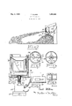
- Figure 1 is an elevational view showing this invention in operation.
- Figure 2 is a sectional view through the distributor mechanism per se.
- Figure 3 is a top plan view of this invention.
- Figure 4 is a sectional view on lined- 1: of Figure '2.
- Figure 5 is an enlarged detail view of the side of the hopper.
- Figure 6 is a section on line 66 of Figure 2.
- the receiving cylinder or hopper for receiving the coal from a coal chute 1 1, the coal chute 11 restingou one side 12 of thewcoal bin.
- An inner-conical rim 13 is provided in the cylinder 10, being affixed thereto by any suitable meansas by welding 1%,the rim 13'h aying an orifice r15 centrally thereof.
- Supported below the orifice 15 is acoal receiving-plate l6, a-Web firising therefrom atone side thereof assisting supporting both the plate 16 and the rim 13, the plate 16 being affixed to the inside of the hopper'in any suitable manner.
- the bottomyof the hopper 10 is formed in a Webb as at 18 and is supported on a bearing 19 on the shaft '20 of an electric motor 21, the motor 21 being enclosed in a housing 22 and lined on a webbed support or legs :23.
- the legs 23 maybe placed either the bottom of a coal bin-or embedded a coal pile 2% when in operation, as :shown in Figure 1 T he shaft is preferably separable, the two sections thereof being joined by a coupling 25 and pins 26.
- the top of the shaft 20 projects through the bottom of the cylinder and rotatably supports a hopper :27 within the cylinder 10, a suitable healing 28 being formed between the bottoms of hopper 27 and ofcylinder 110..
- the rotatable hopper .27 has flaring sides 29, which flare outwardly :so as to prevent any substantial amount of :coal escaping between the-edges of hopper27 and the inside of cylinder 10, it being observed that the webbed bottom of cylinder 10 allow such minor amounts that do escape there/between to fall below.
- wiping blades 30 the bottom edge being flared as at 3.1, are socured to the bottom of hopper27 soas'towipe any coal oh the webs 18, i i
- the hopper '27 is divided into a plurality of compartments 32 and '33, any suitable numher being provided although only two have been shown in the present form.
- the compartments 32 and 33 are divided by a wall 4: and 35, the tops of the walls 34 and 35 each being bent as at 36 and 37, the bend being in the direction that the cylinder is to rotate. Adjacent each wall 34 and 35 an opening 88 is formed for each compartment provided in the hopper 27 .At alevel corresponding to the openings 38, an opening 39 is formed in the side of the cylinder 10.
- the coal from the chute 11 drops onto rim 13 of the cylinder 10 and passes through the orifice 15 onto plate 16.
- the coal then piles up on blade 16 against the web 17 and then falls off from the side opposite the web into a hopper 27.
- the hopper 27 is rotated by the motor 21 in a clockwise direction as observed in Figure 3 so that as the coal falls off the plate 16 it falls in one or the other of the compartments of the hopper 27, the bent edges 36 and 37 of walls 34 and 35,never being in a position to become jammed by coal getting between the same and the bottom of plate 16 due to the fact that the coal is discharged from the plate 16 into the hopper 27 on one side only, theweb 17 prevent-- ing any coal from discharging on the opposite side.
- the rim 13, web 17 and plate 16 also serve to prevent any great shock as the coal drops into the hopper 27.
- a ratch 42 is formed about the bottom of cylinder 10 and a spring secured arm 43 afiixed to housing 22 is adapted to mesh therewith, the arm 43 being hinged to the housing 22 as by a spring hinge 44.
- the arm 43 is retained in the position shown, thereby holding its end in mesh with the ratch 42 preventing the cylinder 10 from rotating.
- the arm 43 is rotated about its hinge 44 against the action of the spring thereon, allowing its end to disengage from the ratch 42 whereby the cylinder 10 may be rotated to face the opening 39 in proper position and the arm 43 is again placed in mesh with ratch 42.
- a centrifugal coal distributor for coal bins or the like comprising a receiving cylinder, an orificed rim secured therein, a plate secured to said cylinder below the orifice of said rim, a web projecting upwardly on one side of said plate, a rotatable hopper within said cylinder below said plate, walls dividing said hopper into a plurality of compartments, the top edges of said walls being bent in the direction said hopper is rotated, each compartment having an opening in the side thereof adjacent said dividing wall, said cylinder having an opening in the same plane with said openings in said hopper compartments, and means for rotating and supporting said hopper within said cylinder.
- a centrifugal coal distributor for coal bins or the like comprising a receiving cylinder, an orificed rim secured therein, a plate secured to said cylinder below the orifice of said rim, a web projecting upwardly on one side of said plate, a rotatable hopper within said cylinder belowv said plate, walls dividing said hopper into a plurality of compartments, the top edges of said walls being bent in the direction said hopper is rotated, each compartment having an opening in the side thereof adjacent said dividing wall, said cylinder having an opening in the same plane with said openings in said hopper compartments, means for rotating and supporting said hopper within said cylinder, a ratch formed on said cylinder, and an arm adapted to mesh with said ratch to releasably hold said cylinder against rotation, said arm being secured on said supporting means.
- a centrifugal coal distributor for coal bins or the like comprising a receiving cylinder, an orificed rim secured therein, a plate secured to said cylinder below the orifice of said rim, a web projecting upwardly on one side of said plate, a rotatable hopper within said cylinder below said plate, walls dividing said hopper into a plurality of compartments, the top edges of said walls being bent in the direction said hopper is rotated, each compartment having an opening in the side thereof adjacent said dividing wall, said!
- a centrifugal coal distributor for coal bins or the like comprising a receiving cylinder, an orificed rim secured therein, a plate secured to said cylinder below the orifice of said rim, a web projecting upwardly on one side of said plate, a rotatable hopper within said cylinder below said plate, walls dividing said hopper into a plurality of compartments, the top edges of said walls being bent in the direction said hopper is rotated, each compartment having an opening in the side thereof adjacent said dividing wall, said cylinder having an opening in the same plane with said openings in said hopper comparti ments, a Webbed bottom for said cylinder, wiping blades secured to the bottom of said rotating hopper, whereby the rotation of said hopper will keep the bottom of said cylinder free of coal, said supporting and rotating means.
Landscapes
- Engineering & Computer Science (AREA)
- Mechanical Engineering (AREA)
- Solid Fuels And Fuel-Associated Substances (AREA)
Description
' May 3, 1932. h T. WILKES 1,856,981
COAL DI STRIBUTOR Fiied Jan. 8, 1932 34; I U |\\\:5\0 q\\- \\v 1 i 6.
gin w nter Patented May 3, 1932 UNITED STATES 'TRAUIB WILKES, OF NEW YORK, N. Y.
COAL DISTRIBUTOR lppfication filed January 8, 1932. Serial No. 585,566.
This invention relates to an improved centrifugal coal distributor and has for an object to provide an improved coal distribution device which will cooperate with acoal a chute for uniformly distributing the coal over a given area.
A further object of this invention is to provide an improved coal distributor which is useful both in coal yards or bins, having a n: large area as well as in holes of ships or in coal cars.
Yet a further object of this invention is to provide a- =centrifugal coal distributor which may be ope-rated to distribute the coal in the desired directions which is easily portable and may be placed on the top of a coal pile beneath a coal discharging chute to distribute the coal at a distancetherefrom.
With the foregoing and other objects in 3 view, as will hereinafter become apparent, this invention comprises the constructions, combinations and arrangement of parts hereinafter set forth, disclosed and shown on the accompanying drawings. In the drawings,
Figure 1 is an elevational view showing this invention in operation.
Figure 2 is a sectional view through the distributor mechanism per se.
Figure 3 is a top plan view of this invention.
Figure 4 is a sectional view on lined- 1: of Figure '2.
Figure 5 is an enlarged detail view of the side of the hopper, and
Figure 6 is a section on line 66 of Figure 2.
There is shown IO'the receiving cylinder or hopper for receiving the coal from a coal chute 1 1, the coal chute 11 restingou one side 12 of thewcoal bin. An inner-conical rim 13 is provided in the cylinder 10, being affixed thereto by any suitable meansas by welding 1%,the rim 13'h aying an orifice r15 centrally thereof. Supported below the orifice 15 is acoal receiving-plate l6, a-Web firising therefrom atone side thereof assisting supporting both the plate 16 and the rim 13, the plate 16 being affixed to the inside of the hopper'in any suitable manner.
The bottomyof the hopper 10 is formed in a Webb as at 18 and is supported on a bearing 19 on the shaft '20 of an electric motor 21, the motor 21 being enclosed in a housing 22 and lined on a webbed support or legs :23. The legs 23 maybe placed either the bottom of a coal bin-or embedded a coal pile 2% when in operation, as :shown in Figure 1 T he shaft is preferably separable, the two sections thereof being joined by a coupling 25 and pins 26. The top of the shaft 20 projects through the bottom of the cylinder and rotatably supports a hopper :27 within the cylinder 10, a suitable healing 28 being formed between the bottoms of hopper 27 and ofcylinder 110.. The rotatable hopper .27 has flaring sides 29, which flare outwardly :so as to prevent any substantial amount of :coal escaping between the-edges of hopper27 and the inside of cylinder 10, it being observed that the webbed bottom of cylinder 10 allow such minor amounts that do escape there/between to fall below. To assure that no such "escape -'coal should should remain on the webbed bottom 18, wiping blades 30, the bottom edge being flared as at 3.1, are socured to the bottom of hopper27 soas'towipe any coal oh the webs 18, i i
The hopper '27 is divided into a plurality of compartments 32 and '33, any suitable numher being provided although only two have been shown in the present form. The compartments 32 and 33 are divided by a wall 4: and 35, the tops of the walls 34 and 35 each being bent as at 36 and 37, the bend being in the direction that the cylinder is to rotate. Adjacent each wall 34 and 35 an opening 88 is formed for each compartment provided in the hopper 27 .At alevel corresponding to the openings 38, an opening 39 is formed in the side of the cylinder 10.
In operation, the coal from the chute 11 drops onto rim 13 of the cylinder 10 and passes through the orifice 15 onto plate 16. The coal then piles up on blade 16 against the web 17 and then falls off from the side opposite the web into a hopper 27. The hopper 27 is rotated by the motor 21 in a clockwise direction as observed in Figure 3 so that as the coal falls off the plate 16 it falls in one or the other of the compartments of the hopper 27, the bent edges 36 and 37 of walls 34 and 35,never being in a position to become jammed by coal getting between the same and the bottom of plate 16 due to the fact that the coal is discharged from the plate 16 into the hopper 27 on one side only, theweb 17 prevent-- ing any coal from discharging on the opposite side. The rim 13, web 17 and plate 16 also serve to prevent any great shock as the coal drops into the hopper 27.
As the hopper 27 rotates centrifugal force operates to move the coal outwardly from the sides thereof tending to cause the coal to pass out of openings 38 in the sides of hopper 27. Each time the opening 38 is in alignment with opening 39 in the side of cylinder 10, coal in that compartment will pass through the opening 39 in a stream as at 40, centrifugal force carrying this stream over to the opposite side of the hopper, the distance that it is carried depending on the speed at which the motor is operated, the operation of the motor being controlled by an appropriate switch connected with a power supply conduit 41. A ratch 42 is formed about the bottom of cylinder 10 and a spring secured arm 43 afiixed to housing 22 is adapted to mesh therewith, the arm 43 being hinged to the housing 22 as by a spring hinge 44. Ordinarily the arm 43 is retained in the position shown, thereby holding its end in mesh with the ratch 42 preventing the cylinder 10 from rotating. When it is desired to change the direction that the coal is being distributed, the arm 43 is rotated about its hinge 44 against the action of the spring thereon, allowing its end to disengage from the ratch 42 whereby the cylinder 10 may be rotated to face the opening 39 in proper position and the arm 43 is again placed in mesh with ratch 42.
The novel features and the operation of this device will be apparent from the foregoing description. While the device has been shown and the structure described in detail. it is obvious that this is not to be considered limited to the exact form disclosed and that changes may be made therein within the scope of what is claimed without departing from the spirit of the invention.
Having thus set forth and disclosed the nature of this invention, what is claimed is:
1. A centrifugal coal distributor for coal bins or the like comprising a receiving cylinder, an orificed rim secured therein, a plate secured to said cylinder below the orifice of said rim, a web projecting upwardly on one side of said plate, a rotatable hopper within said cylinder below said plate, walls dividing said hopper into a plurality of compartments, the top edges of said walls being bent in the direction said hopper is rotated, each compartment having an opening in the side thereof adjacent said dividing wall, said cylinder having an opening in the same plane with said openings in said hopper compartments, and means for rotating and supporting said hopper within said cylinder.
2. A centrifugal coal distributor for coal bins or the like comprising a receiving cylinder, an orificed rim secured therein, a plate secured to said cylinder below the orifice of said rim, a web projecting upwardly on one side of said plate, a rotatable hopper within said cylinder belowv said plate, walls dividing said hopper into a plurality of compartments, the top edges of said walls being bent in the direction said hopper is rotated, each compartment having an opening in the side thereof adjacent said dividing wall, said cylinder having an opening in the same plane with said openings in said hopper compartments, means for rotating and supporting said hopper within said cylinder, a ratch formed on said cylinder, and an arm adapted to mesh with said ratch to releasably hold said cylinder against rotation, said arm being secured on said supporting means.
3. A centrifugal coal distributor for coal bins or the like comprising a receiving cylinder, an orificed rim secured therein, a plate secured to said cylinder below the orifice of said rim, a web projecting upwardly on one side of said plate, a rotatable hopper within said cylinder below said plate, walls dividing said hopper into a plurality of compartments, the top edges of said walls being bent in the direction said hopper is rotated, each compartment having an opening in the side thereof adjacent said dividing wall, said! cylinder having an opening in the same plane with said openings in said hopper compartments, a webbed bottom for said cylinder, and wiping blades secured to the bottom of said rotating hopper, whereby the rotation of said hopper will keep the bottom of said cylinder free of coal.
4. A centrifugal coal distributor for coal bins or the like comprising a receiving cylinder, an orificed rim secured therein, a plate secured to said cylinder below the orifice of said rim, a web projecting upwardly on one side of said plate, a rotatable hopper within said cylinder below said plate, walls dividing said hopper into a plurality of compartments, the top edges of said walls being bent in the direction said hopper is rotated, each compartment having an opening in the side thereof adjacent said dividing wall, said cylinder having an opening in the same plane with said openings in said hopper comparti ments, a Webbed bottom for said cylinder, wiping blades secured to the bottom of said rotating hopper, whereby the rotation of said hopper will keep the bottom of said cylinder free of coal, said supporting and rotating means. comprising a Web support, a motor secured thereon, and a shaft projecting upwardly from said motor through the bottom of said cylinder and secured to said hopper, said shaft being separable.
In testimony whereof I afiix my signature.
TRAUB WILKES.
Priority Applications (1)
| Application Number | Priority Date | Filing Date | Title |
|---|---|---|---|
| US585566A US1856981A (en) | 1932-01-08 | 1932-01-08 | Coal distributor |
Applications Claiming Priority (1)
| Application Number | Priority Date | Filing Date | Title |
|---|---|---|---|
| US585566A US1856981A (en) | 1932-01-08 | 1932-01-08 | Coal distributor |
Publications (1)
| Publication Number | Publication Date |
|---|---|
| US1856981A true US1856981A (en) | 1932-05-03 |
Family
ID=24342012
Family Applications (1)
| Application Number | Title | Priority Date | Filing Date |
|---|---|---|---|
| US585566A Expired - Lifetime US1856981A (en) | 1932-01-08 | 1932-01-08 | Coal distributor |
Country Status (1)
| Country | Link |
|---|---|
| US (1) | US1856981A (en) |
-
1932
- 1932-01-08 US US585566A patent/US1856981A/en not_active Expired - Lifetime
Similar Documents
| Publication | Publication Date | Title |
|---|---|---|
| US3656697A (en) | Tire pulverizer | |
| US271138A (en) | Necic | |
| US1965033A (en) | Garbage reducing machine | |
| US2114557A (en) | Ice slinger | |
| US1856981A (en) | Coal distributor | |
| US3282591A (en) | Material spreader | |
| US1840602A (en) | Fertilizer and lime spreader | |
| US2297382A (en) | Bag filling machine | |
| JP2777775B2 (en) | Garbage processing equipment | |
| US1731956A (en) | Pulverizing machine | |
| US1134220A (en) | Feed-mixing machine. | |
| US1010062A (en) | Pulverizing-mill. | |
| US2873920A (en) | Crusher | |
| US2810558A (en) | Concrete mixers | |
| US1030042A (en) | Apparatus for separating refuse from coal. | |
| US1643423A (en) | Material-dispensing means for poisoning machines | |
| US1185182A (en) | Moistening device for abrasive wheels. | |
| US844842A (en) | Combined feeding, cleaning, and elevating apparatus. | |
| JPH0579364U (en) | Automatic ice machine | |
| US841273A (en) | Concrete-mixing machine. | |
| US1547802A (en) | Stucco-applying device | |
| US2670883A (en) | Spreader and seeder apparatus | |
| US1086129A (en) | Coal breaker and cleaner. | |
| US1351622A (en) | Ice-cream freezer | |
| US1941603A (en) | Coal breaker |