US1856956A - Projecting machine - Google Patents
Projecting machine Download PDFInfo
- Publication number
- US1856956A US1856956A US428800A US42880030A US1856956A US 1856956 A US1856956 A US 1856956A US 428800 A US428800 A US 428800A US 42880030 A US42880030 A US 42880030A US 1856956 A US1856956 A US 1856956A
- Authority
- US
- United States
- Prior art keywords
- plate
- bolt
- barrel
- projecting
- characters
- Prior art date
- Legal status (The legal status is an assumption and is not a legal conclusion. Google has not performed a legal analysis and makes no representation as to the accuracy of the status listed.)
- Expired - Lifetime
Links
- 238000010276 construction Methods 0.000 description 2
- 238000005192 partition Methods 0.000 description 2
- 229940000425 combination drug Drugs 0.000 description 1
Images
Classifications
-
- G—PHYSICS
- G03—PHOTOGRAPHY; CINEMATOGRAPHY; ANALOGOUS TECHNIQUES USING WAVES OTHER THAN OPTICAL WAVES; ELECTROGRAPHY; HOLOGRAPHY
- G03B—APPARATUS OR ARRANGEMENTS FOR TAKING PHOTOGRAPHS OR FOR PROJECTING OR VIEWING THEM; APPARATUS OR ARRANGEMENTS EMPLOYING ANALOGOUS TECHNIQUES USING WAVES OTHER THAN OPTICAL WAVES; ACCESSORIES THEREFOR
- G03B21/00—Projectors or projection-type viewers; Accessories therefor
Definitions
- This invention relates to a device for projecting letters, figures and designs upon blank cardboard or the like so that the letters, characters or designs can'be easily and quickly sketched or otherwise marked on the surface, thereby eliminating the sketching in ofthe letters, etc., in the usual manner and permitting beginners as well as experienced operators to accurately place the letters, etc. on a surface in the minimum amount of time.
- Figure 2 is a top plan view. 7
- Figure 3 is a section on line 33 of Figure 2.
- Figure 4 is a section on line. 1-4 of Figure 3.
- Figure 6 is a sectional view vation of the' film holder.
- Figure 8 is a view showing the parts with a bottom plan view of the departly in elethe projector in horizontal position.
- the numeral 1 indicates s the base of the apparatus and the numera 2 a rod having one end threaded in the base.
- a tubular rod 3 telescopes the rod 2 and is held in adjusted position thereon by the set screw 4.
- a sleeve 5 is slidably arranged on the rod 3 and is heldin adjusted position by the set screw 6.
- a horizontal rod 7 has one end threaded in the sleeve 5 and the body 8 of the projecting device A is 1 adapted to be fastened to the outer end of this rod 7 either in a horizontal position'or a vertical position.
- the rod 7 When the device is to be held in a vertical the rays of light from the lamp the barrel and registerin with position, the rod 7 has its threaded outer end passed through a hole 9 in one side of the body and fastened thereto by a nut 10. When the device is to beheld in a horizontal position, the threaded end of the rod is passed through a hole'in an angle bracket 11 on the body and fastened to the bracket by the nut 10.
- This latter arrangement is shown in Figure 8.
- the upper end of the body 8 is closed by a cap 12 which carries the lamp socket 13, the lamp being shown at 14, it being understood that the socket is connected with'a suitable source of electrical supply.
- a partition 15 is located in the lower end of the body and has ahole 16 therein through which pass.
- a plate 17 is held in spaced relation rom the lower end of the body bythe strips 19 and this plate has a small hole 20 in its center through which the .rays of light passing through the holes 16 pass.
- a second plate 21 is connected with the plate 17 for swinging movement by the bolt 22 having the spring 23 thereon for-preventing free movement of the plate 21, the bolt passing through the two plates adjacent the edges thereof.
- a barrel 24 has one end connected with the plate 21 at the center thereof and said plate 21 has a hole 25. therein located at the axis of e hole 20 when the plate 21-is in operative position.
- the usual lens barrel26 is carried by the barrel 24.
- a bolt 27 is slidably supported by the plate 17 by passing through a slot 28 in the plate adjacentone edge thereof, the bolt carrying the nut29 and a washer 30, with a spring 31 on the bolt for causing the washer to clamp the plate 17 between itself and the nut 29, so -that-the bolt is frictionally held against slid-- ing movement on the plate 17.
- a nut 32 on the bolt is provided for tensioning the spring.
- the character carrying member or film is shown at 33 and has a hole in its center to fit which are-to be projected, these characters,
- the characters can be placed in two annular rows on the member 33, so that when the bolt is in one position, the characters of one row will be brought in proecting position between the openings 20 and by rotating the member and by moving the bolt to its other position, the characters of the other row will be brought intoprojecting position by rotating the member.
- the character or the like can be easily and quickly sketched or otherwise stripsextending from the perforated end of the body, a plate fastened to the outer ends of the strips and having a central perforation therein and a slotadjacent one edge thereof, a bolt slidably arranged in the slot, spring means for frictionall holding the bolt in adjusted position, a member rotatably and removably arranged on the bolt and carrying annular rows of characters or the like to be projected, a barrel carrying plate pivoted adjacent one edge to the first. plate, the rotatably supported member extending between the two'plates and a'lens carrying barrel carried by the barrel of the plate.
- a character in either row' can be brought into projecting position by adjusting the bolt 27 in the slot 28 and the barrel carrying plate 21 can be swung out of the way to permit a new member 33 to be substituted for the old one, as the plate 21 is' formed witha notch 21' for'receiving the nut 34,.so that by removing-the nut, said plate 21 is free to swing on its pivot.
- the size of the characters may be varied by adjusting the distance between the lens and the sheet by raising or lowering the device and then fastening it in adjusted posi-v tion by the set screws 4 and 6.
- a projecting device of the class described comprising a body having an opening at one end thereof, a lamp in the body, a perforated plate spaced from that end of the body which is formed with the opening, a barrel carrying plate pivoted to the first plate, means for rotatably connecting a member carrying the matter to be projected to the first plate and means whereby the pivotal point of said member can be adjusted toward and away from the perforation in the plate.
- a projecting device of the class de-- scribed comprising a hollow body having an opening in one end thereof, a cap closing the other end, a lamp socket carried by the cap,
Landscapes
- Physics & Mathematics (AREA)
- General Physics & Mathematics (AREA)
- Illuminated Signs And Luminous Advertising (AREA)
Description
y 1932- H. B. JORDAN 1,856,956
PROJECTING MACHINE Original Filed Feb. 15, 1930 2 SheetsSheet -l INVENTOR ATTORNEY 5 1227x795. (707mm,
y 1932- H. B. JORDAN 1,856,956
PROJECTING MACHINE Original Filed Feb. 15, 1950 2 Sheets-Sheet 2 Janiaiz,
INVENTOR ATTORNEY Patented May 3, 1932 FATE NTW OFFICE.
This invention relates to a device for projecting letters, figures and designs upon blank cardboard or the like so that the letters, characters or designs can'be easily and quickly sketched or otherwise marked on the surface, thereby eliminating the sketching in ofthe letters, etc., in the usual manner and permitting beginners as well as experienced operators to accurately place the letters, etc. on a surface in the minimum amount of time.
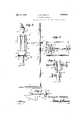
This invention also consists in certain other features of construction and in the combination and arrangement of the several parts, to be hereinafter fully described, illustrated in the accompanying drawings and specifically pointed out in the" appended In describing the invention in detail, reference will be had to the accompanying drawings wherein like characters denote like or corresponding parts throughout the several views, and in which Figure 1 is an elevation of the device.
Figure 2 is a top plan view. 7
Figure 3 is a section on line 33 of Figure 2. a
Figure 4 is a section on line. 1-4 of Figure 3.
Figure 5 is vice. I
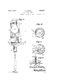
Figure 6 is a sectional view vation of the' film holder.
*Figure 7 is a sectional view through the upright.
Figure 8 is a view showing the parts with a bottom plan view of the departly in elethe projector in horizontal position.
In these views, the numeral 1 indicat s the base of the apparatus and the numera 2 a rod having one end threaded in the base. A tubular rod 3 telescopes the rod 2 and is held in adjusted position thereon by the set screw 4. A sleeve 5 is slidably arranged on the rod 3 and is heldin adjusted position by the set screw 6. A horizontal rod 7 has one end threaded in the sleeve 5 and the body 8 of the projecting device A is 1 adapted to be fastened to the outer end of this rod 7 either in a horizontal position'or a vertical position.
When the device is to be held in a vertical the rays of light from the lamp the barrel and registerin with position, the rod 7 has its threaded outer end passed through a hole 9 in one side of the body and fastened thereto by a nut 10. When the device is to beheld in a horizontal position, the threaded end of the rod is passed through a hole'in an angle bracket 11 on the body and fastened to the bracket by the nut 10. This latter arrangement is shown in Figure 8. The upper end of the body 8 is closed by a cap 12 which carries the lamp socket 13, the lamp being shown at 14, it being understood that the socket is connected with'a suitable source of electrical supply. .A partition 15 is located in the lower end of the body and has ahole 16 therein through which pass. A
A bolt 27 is slidably supported by the plate 17 by passing through a slot 28 in the plate adjacentone edge thereof, the bolt carrying the nut29 and a washer 30, with a spring 31 on the bolt for causing the washer to clamp the plate 17 between itself and the nut 29, so -that-the bolt is frictionally held against slid-- ing movement on the plate 17. A nut 32 on the bolt is provided for tensioning the spring.
.The character carrying member or film is shown at 33 and has a hole in its center to fit which are-to be projected, these characters,
-over the lower end of the bolt 27 and said of course, being transparent. By having .the bolt 27 slidably arranged, the characters can be placed in two annular rows on the member 33, so that when the bolt is in one position, the characters of one row will be brought in proecting position between the openings 20 and by rotating the member and by moving the bolt to its other position, the characters of the other row will be brought intoprojecting position by rotating the member.
From the \foregoing it will be seen that when thelamp is lighted, the rays of light 7, will pass through the opening 16 in the partition and through the openings 20 and 25 in the plates 17 and 21 and then through the barrels and the lenses carried by the barrel 26 and thus the character opposite the openings 20 and 25 will beprojected on to a sheet or the like placed on the b so 1, as shown in- Figure 3. Thus the character or the like can be easily and quickly sketched or otherwise stripsextending from the perforated end of the body, a plate fastened to the outer ends of the strips and having a central perforation therein and a slotadjacent one edge thereof, a bolt slidably arranged in the slot, spring means for frictionall holding the bolt in adjusted position, a member rotatably and removably arranged on the bolt and carrying annular rows of characters or the like to be projected, a barrel carrying plate pivoted adjacent one edge to the first. plate, the rotatably supported member extending between the two'plates and a'lens carrying barrel carried by the barrel of the plate.
In testimony whereof I afiix my signature.
HENRY B. JORDAN.
drawn on the sheet. To bring a new character into projecting position, it is simply neces-' sary to turn the member '33 and other members can be readily substituted for said member when desired by removing the screw 34.
As before stated, a character in either row' can be brought into projecting position by adjusting the bolt 27 in the slot 28 and the barrel carrying plate 21 can be swung out of the way to permit a new member 33 to be substituted for the old one, as the plate 21 is' formed witha notch 21' for'receiving the nut 34,.so that by removing-the nut, said plate 21 is free to swing on its pivot.
The size of the characters may be varied by adjusting the distance between the lens and the sheet by raising or lowering the device and then fastening it in adjusted posi-v tion by the set screws 4 and 6.
It isthought from the foregoing description that the advantages and novel features of the inzvhtion will be readily apparent.
It is to be understood that changes may be made in the construction and in the combina tion and arrangement of the several parts, provided that such changes fall within the l I scope of the appended claims.
What I'claim is j 1. A projecting device of the class described comprising a body having an opening at one end thereof, a lamp in the body, a perforated plate spaced from that end of the body which is formed with the opening, a barrel carrying plate pivoted to the first plate, means for rotatably connecting a member carrying the matter to be projected to the first plate and means whereby the pivotal point of said member can be adjusted toward and away from the perforation in the plate.
2. A projecting device of the class de-- scribed comprising a hollow body having an opening in one end thereof, a cap closing the other end, a lamp socket carried by the cap,
Priority Applications (1)
| Application Number | Priority Date | Filing Date | Title |
|---|---|---|---|
| US428800A US1856956A (en) | 1930-02-15 | 1930-02-15 | Projecting machine |
Applications Claiming Priority (1)
| Application Number | Priority Date | Filing Date | Title |
|---|---|---|---|
| US428800A US1856956A (en) | 1930-02-15 | 1930-02-15 | Projecting machine |
Publications (1)
| Publication Number | Publication Date |
|---|---|
| US1856956A true US1856956A (en) | 1932-05-03 |
Family
ID=23700449
Family Applications (1)
| Application Number | Title | Priority Date | Filing Date |
|---|---|---|---|
| US428800A Expired - Lifetime US1856956A (en) | 1930-02-15 | 1930-02-15 | Projecting machine |
Country Status (1)
| Country | Link |
|---|---|
| US (1) | US1856956A (en) |
Cited By (5)
| Publication number | Priority date | Publication date | Assignee | Title |
|---|---|---|---|---|
| US2573546A (en) * | 1949-10-11 | 1951-10-30 | Frank D Costenbader | Eye testing instrument |
| US2846921A (en) * | 1956-07-16 | 1958-08-12 | Glass | Device for selectively forming various pictorial representations and for projecting same on a viewer |
| US2957695A (en) * | 1956-05-22 | 1960-10-25 | Arizpe Harmodio De Valle | Target projection apparatus |
| US5477283A (en) * | 1993-05-24 | 1995-12-19 | Casey; Alan F. | Image projecting device |
| US6206524B1 (en) * | 1997-03-07 | 2001-03-27 | Daniel Jacob | Lensless transparency shadowgraph |
-
1930
- 1930-02-15 US US428800A patent/US1856956A/en not_active Expired - Lifetime
Cited By (5)
| Publication number | Priority date | Publication date | Assignee | Title |
|---|---|---|---|---|
| US2573546A (en) * | 1949-10-11 | 1951-10-30 | Frank D Costenbader | Eye testing instrument |
| US2957695A (en) * | 1956-05-22 | 1960-10-25 | Arizpe Harmodio De Valle | Target projection apparatus |
| US2846921A (en) * | 1956-07-16 | 1958-08-12 | Glass | Device for selectively forming various pictorial representations and for projecting same on a viewer |
| US5477283A (en) * | 1993-05-24 | 1995-12-19 | Casey; Alan F. | Image projecting device |
| US6206524B1 (en) * | 1997-03-07 | 2001-03-27 | Daniel Jacob | Lensless transparency shadowgraph |
Similar Documents
| Publication | Publication Date | Title |
|---|---|---|
| US1856956A (en) | Projecting machine | |
| US2059361A (en) | Color screen holder | |
| US2341223A (en) | Advertising projection | |
| US1388110A (en) | Punch-centering device | |
| US2295210A (en) | Illuminated platen | |
| US3242581A (en) | Vertex refractionometer with marking device | |
| US1712431A (en) | Design generation | |
| US2159614A (en) | Image projection cabinet | |
| US2935797A (en) | Apparatus for displaying the properties of light | |
| US1373491A (en) | Picture-projector | |
| US2293597A (en) | Magnifying device | |
| US2194818A (en) | Signaling device | |
| US2388837A (en) | Print making machine | |
| US1920183A (en) | Microscopic projector | |
| US1958275A (en) | Lens testing instrument | |
| US1296432A (en) | Retouching-frame. | |
| US1983108A (en) | Reflecting device | |
| US2205965A (en) | Apparatus for exercising the eyes | |
| US992222A (en) | Protector. | |
| US1570498A (en) | Film-printing machine | |
| US1355397A (en) | Optical instrument | |
| SU4850A1 (en) | Music stand for typewriter | |
| US1141801A (en) | Display-sign for store-windows. | |
| US2256424A (en) | Projector | |
| US895034A (en) | Attachment for photograhic-printing apparatus. |