US1856940A - Apparatus for the production of ornamental chains, so called snake chains - Google Patents
Apparatus for the production of ornamental chains, so called snake chains Download PDFInfo
- Publication number
- US1856940A US1856940A US474982A US47498230A US1856940A US 1856940 A US1856940 A US 1856940A US 474982 A US474982 A US 474982A US 47498230 A US47498230 A US 47498230A US 1856940 A US1856940 A US 1856940A
- Authority
- US
- United States
- Prior art keywords
- link
- matrix
- chains
- casing
- feed
- Prior art date
- Legal status (The legal status is an assumption and is not a legal conclusion. Google has not performed a legal analysis and makes no representation as to the accuracy of the status listed.)
- Expired - Lifetime
Links
- 241000270295 Serpentes Species 0.000 title description 7
- 238000004519 manufacturing process Methods 0.000 title description 4
- 239000011159 matrix material Substances 0.000 description 39
- 239000002184 metal Substances 0.000 description 8
- 238000000034 method Methods 0.000 description 4
- 241001527902 Aratus Species 0.000 description 1
- 241000905957 Channa melasoma Species 0.000 description 1
- 208000027697 autoimmune lymphoproliferative syndrome due to CTLA4 haploinsuffiency Diseases 0.000 description 1
- 238000006073 displacement reaction Methods 0.000 description 1
- 235000015250 liver sausages Nutrition 0.000 description 1
- 238000003825 pressing Methods 0.000 description 1
Images

Classifications
-
- B—PERFORMING OPERATIONS; TRANSPORTING
- B21—MECHANICAL METAL-WORKING WITHOUT ESSENTIALLY REMOVING MATERIAL; PUNCHING METAL
- B21L—MAKING METAL CHAINS
- B21L11/00—Making chains or chain links of special shape
- B21L11/005—Making ornamental chains
Definitions
- JOSEF AL1TERA AND KARL SCHOFER, or 'rFonznEm, GERMANY J APPARATUS ron THE rnonoorron or ORNAMENTAL SNAKE cn'AINs- Ap 'aratus have become known for the manu acturing of so called snake chains.
- These chains are composed of two kinds of links, namely the casing links, vhich .form
- the method according to the invention differs from the known methods forproducing chains of-this type in that two groups of tools act alternately so that the chain is made in two-cycle operation.
- ig. 2 being a side elevation of Fig. 1.
- Fig. 3 shows the second group of tools in to plan view.
- ig. 4 being a side elevation of Fig. 3.
- Fig. 5 shows the stamped blank of a connecting link in plan View.
- Fi 6 shows the stamped blank of the casing hnk in plan view.
- Fig. 7 is a section on line 7-7 of Fig. 9.
- Fig. 8 is a section on line 8-8 of Fig. 10.
- Fig. 9 is a top plan view of a connecting link in finished shape.
- Fig. 10 is-a top plan view of a casing link in finished shape.
- Fig. 11 is a sectionfon line 11-11 :of Fig. 12.
- Fig. 12 shows in-top plan View the two links inserted one within the other.
- Both the connecting links as also the casing links are stamped in known manner from sheet metal strips.
- the connecting link is effected in the first cycle in and that of the casing link in the second cycle.
- the group of tools cooperating infl the first'cycle consists of the matrix plate first groi1p of tools Accordingto the method I covered by the invention the stampingof theplate a. and 4) is in its extreme front position, the 'matrix hole a is situated exactly below the slums, so eA L n Application filed Au ust 1s, 1980, Serial lfio. 474,982, and in Germany August 17, 1929.
- a sheet metal strip a is fedover the matrix .5 plate a. In the extreme rear position of the matrix. plate a (Figs. 1 and 2) thematrix holea issituated exactly under the die d, which then stamps the connecting link out of the sheet metal strip win the first cycle.
- the matrix plate a After the completion of this first cycle the matrix plate a is shifted into its extreme front position (Figs. 3 and 4), carrying along the connecting link in the matrix hole a Through this displacement the matrix hole (11 ch with the .bore' a of the matrix plate comes to lie, exactly over the hole 0 of the feed arm 0.
- the connecting link is pushed by the feed ram 2' out .of the matrix hole (1 into the bore. (1 of them matrix plate andinto' the hole 0, of the feed armc.
- the armss By the pressing of the fiat connecting link intot'he bore a of the matrix plate thearms are bent up so that the connecting link assumes the shape of a tripod. 7 In thisshape it is in the .hole c of the feed.
- feed arms I) and a, as also of the stamping dies d, g and feed rams e, k, i are preferably effected from one and t e same cam shaft.
- a third ram adapted to force from Below the connecting link out of said connecting link feeding arm into said casing link feeding arm carrying the casing link ejected from said matrix plate by said second ram and thereby to connect the connecting link with the casing link, a chain forming matrix under said casing link feeding arm, and a fourth ramadapted to eject the pair of connected links out of said casing link feeding arm into said chain forming matrix.
- a movable connecting link feeding arm -'a casing link feeding arm oppositely ,movable to said connecting link feeding arm, a matrix plate having a connecting link matrix hole and a casing link matrix hole shiftable transversely to and adapted to cooperate with said feedin arms, a chain'forming matrix under one of sai feeding arms, a group of tools one of which is adapted, when said feeding arms are the one above the other and said matrix plateis in pulled back position, to stamp a connecting link from a sheet metal strip and to feed this stamped blank or connecting link into the connecting link hole in said matrix plate, two oppositely moving rams of said group of tools adapted to force a previously stamped connecting link together with a casing link previously stamped from a second sheet metal strip fed over said matrix plate into said casing link feeding arm, and a second group of tools adapted, when said feeding arms have been pulled back and said, matrix plate is in its pushed forward 081- tion, to force a stamped connecting link rom said matrix plate into saidj'connect
Landscapes
- Engineering & Computer Science (AREA)
- Mechanical Engineering (AREA)
- Press Drives And Press Lines (AREA)
Description
y 1932- J. ALVERA ET AL 1,856,940
APPARATUS FOR THE PRODUCTION OF ORNAMENTAL CHAINS, so CALLED SNAKE CHAINS Filed Aug. 13, 1930 2 Sheets-Sheet 1 m drw May? 1932- J ALVERA ET AL ,940
APPARATUS FOR THE PRODUCTION OF ORNAMFIN'IAL CHAINS, SO CALLED SNAKE CHAINS Ell Patented May 3, 19 32 ,ji -aaw UNITED STATES} PATE T arms,
JOSEF AL1TERA AND KARL SCHOFER, or 'rFonznEm, GERMANY J APPARATUS ron THE rnonoorron or ORNAMENTAL SNAKE cn'AINs- Ap 'aratus have become known for the manu acturing of so called snake chains.
, These chains are composed of two kinds of links, namely the casing links, vhich .form
the outer sides, and the conne ting links, which connect the casing links.
The method according to the invention differs from the known methods forproducing chains of-this type in that two groups of tools act alternately so that the chain is made in two-cycle operation.
The new method is illustrated by way of example in the accompanying di3awings in which a Fi 1 shows the to p an view. v a
ig. 2 being a side elevation of Fig. 1.
Fig. 3 shows the second group of tools in to plan view. v
ig. 4 being a side elevation of Fig. 3.
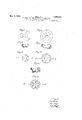
Fig. 5 shows the stamped blank of a connecting link in plan View.
Fi 6 shows the stamped blank of the casing hnk in plan view.
Fig. 7 is a section on line 7-7 of Fig. 9.
Fig. 8 .is a section on line 8-8 of Fig. 10.
Fig. 9 is a top plan view of a connecting link in finished shape.
Fig. 10 is-a top plan view of a casing link in finished shape.
Fig. 11 is a sectionfon line 11-11 :of Fig. 12.
Fig. 12 shows in-top plan View the two links inserted one within the other.
Both the connecting links as also the casing links are stamped in known manner from sheet metal strips.
connecting link is effected in the first cycle in and that of the casing link in the second cycle. .The group of tools cooperating infl the first'cycle consists of the matrix plate first groi1p of tools Accordingto the method I covered by the invention the stampingof theplate a. and 4) is in its extreme front position, the 'matrix hole a is situated exactly below the slums, so eA L n Application filed Au ust 1s, 1980, Serial lfio. 474,982, and in Germany August 17, 1929.
The roduction and feeding of the connecting lin s, which have three arms slightly enlarged at their ends, is effected in the followingmanner:
A sheet metal strip a: is fedover the matrix .5 plate a. In the extreme rear position of the matrix. plate a (Figs. 1 and 2) thematrix holea issituated exactly under the die d, which then stamps the connecting link out of the sheet metal strip win the first cycle.
After the completion of this first cycle the matrix plate a is shifted into its extreme front position (Figs. 3 and 4), carrying along the connecting link in the matrix hole a Through this displacement the matrix hole (11 ch with the .bore' a of the matrix plate comes to lie, exactly over the hole 0 of the feed arm 0. During the second cyclethe connecting link is pushed by the feed ram 2' out .of the matrix hole (1 into the bore. (1 of them matrix plate andinto' the hole 0, of the feed armc. By the pressing of the fiat connecting link intot'he bore a of the matrix plate thearms are bent up so that the connecting link assumes the shape of a tripod. 7 In thisshape it is in the .hole c of the feed.
arm a at the end of the second cycle. Only. a i
during the following cycle, which must-be also regarded as a first cycle because the next connecting link is stamped out of the sheetinetal strip 00, the. connecting of the conncctin g link with a casing link is effected by push .ing the" former intothe hole 6 of the feed arm I) by means of the-feed ram "f, into which hole the casing link is also pushed during this cycle by means of the feed ram e. I
The production and feeding ofthe casing link, which consists of a circular rim provided with three spokes, is effected in the .following manner: f
.\ sheet metal strip is fed over the matrix When the matrix plate a (Figs.'3
die 9, which stamps the casing link-from the sheet metal strip-y only duringthe second cycle.
On the completion of this second cycle the matrix plate a shifts into its rear extreme position :(Figs. 1 and 2), taking back the casing link lying in the matrix 'hole a 10.
:from the opposite side by means of the ram link is pushed by means of the feed ram 0 out of the bore a; of the matrix, the circular rim being bent up into the bore a, of the matrix plate-and further-into the hole 72 in which the connecting link is pushed at the same time f in such a manner that the free arms of this connecting. hnk engage between the three spokes of the casing link and aresecurely hooked thereon by the enlarged ends of the arms. 7
' After the completion of the first cycle the two feed arms 6 and emove apart from the position shown in Figs. 1 and 2 into that shown in Figs. 3 and 4. Thus the hole 6 of the feed arm I), in which a connected pair of links is located, comes over the coneshaped enlargement of a hole k of-a chain forming matrix is, into which it is pushed by means ofva ram h during'the second cycle of the machine. The connection of thepair of links with the length of chain m in the chain forming matrix I: effected in known manner.
In the two cycles of the device forming the entire chain producing operation, the following occurs ateach cycle:
In the first cycle, in which the two feed arms I) and c are situated the one above the other and the matrix plate a is in its extreme rear posit-ion, a connecting link is stamped, asecond connect-in link already in' the feeding arm '0 is pushe from 'belowby means of the ram f intothe feed arm I) and at the same time connected to form a pair of links with the casing link fed from above into the arm 6 by means of the ram e.
Inthe second cycle, before the commencement of which the arms 6 and a have moved a'partand the matrix plate a has passed into its extreme front position, a casing link is stamped, a connecting link alreadyin the matrix plate a is pushed by means of the ram i into the feed arm a an the pair of links already in the feed arm 6 is fed intothe 'chai'n forming matrix In by means -of the ram h.
Ilhe movements of the matrix plate a, the
feed arms I) and a, as also of the stamping dies d, g and feed rams e, k, i are preferably effected from one and t e same cam shaft. 1, We claim:
out of said plate into said casing link feeding arm when said plate is in its extreme rear osition, a third ram adapted to force from Below the connecting link out of said connecting link feeding arm into said casing link feeding arm carrying the casing link ejected from said matrix plate by said second ram and thereby to connect the connecting link with the casing link, a chain forming matrix under said casing link feeding arm, and a fourth ramadapted to eject the pair of connected links out of said casing link feeding arm into said chain forming matrix. 2. In a snake chain making machine a movable connecting link feeding arm,-'a casing link feeding arm oppositely ,movable to said connecting link feeding arm, a matrix plate having a connecting link matrix hole and a casing link matrix hole shiftable transversely to and adapted to cooperate with said feedin arms,a chain'forming matrix under one of sai feeding arms, a group of tools one of which is adapted, when said feeding arms are the one above the other and said matrix plateis in pulled back position, to stamp a connecting link from a sheet metal strip and to feed this stamped blank or connecting link into the connecting link hole in said matrix plate, two oppositely moving rams of said group of tools adapted to force a previously stamped connecting link together with a casing link previously stamped from a second sheet metal strip fed over said matrix plate into said casing link feeding arm, and a second group of tools adapted, when said feeding arms have been pulled back and said, matrix plate is in its pushed forward 081- tion, to force a stamped connecting link rom said matrix plate into saidj'connecting link feed arm, the arms of the casing being bentup, to stamp a casing link from the second strip of sheet metal and to force this stamped ,out casing link into the casing link hole in said matrix plate and to eject the previously formed pair of links from said casingilink arm and feed this pairof elements into said chain forming matrix. I
In testimony whereof we afiix our signatures.
J OSEF ALVERA. KARE SCHOFER.
1. In a snake chain making machine a con-; nectrng link feedin arm, a casing lmk feeding arm, a shiftabl e' matrix plate for both the connecting links and the casing links, a ram' adapted to force a'stamped connecting; link out of said plate into said connecting lgnk feeding.- arm when said plate is'in its xtreme forward position, a second feeding ram adapted to force the stamped casing link
Applications Claiming Priority (1)
| Application Number | Priority Date | Filing Date | Title |
|---|---|---|---|
| DE1856940X | 1929-08-17 |
Publications (1)
| Publication Number | Publication Date |
|---|---|
| US1856940A true US1856940A (en) | 1932-05-03 |
Family
ID=7746271
Family Applications (1)
| Application Number | Title | Priority Date | Filing Date |
|---|---|---|---|
| US474982A Expired - Lifetime US1856940A (en) | 1929-08-17 | 1930-08-13 | Apparatus for the production of ornamental chains, so called snake chains |
Country Status (1)
| Country | Link |
|---|---|
| US (1) | US1856940A (en) |
Cited By (1)
| Publication number | Priority date | Publication date | Assignee | Title |
|---|---|---|---|---|
| US2650469A (en) * | 1948-09-24 | 1953-09-01 | Marquardt Max | Manufacture of flexible chains |
-
1930
- 1930-08-13 US US474982A patent/US1856940A/en not_active Expired - Lifetime
Cited By (1)
| Publication number | Priority date | Publication date | Assignee | Title |
|---|---|---|---|---|
| US2650469A (en) * | 1948-09-24 | 1953-09-01 | Marquardt Max | Manufacture of flexible chains |
Similar Documents
| Publication | Publication Date | Title |
|---|---|---|
| US3774435A (en) | Method and apparatus for making bearings | |
| US1850679A (en) | Process and apparatus for forming bushings | |
| US1856940A (en) | Apparatus for the production of ornamental chains, so called snake chains | |
| US2183287A (en) | Horizontal redraw press | |
| US2069511A (en) | Upsetting mechanism | |
| US2231286A (en) | Method and apparatus for forming and attaching slide fastener elements | |
| US2447499A (en) | Brush-stem forming machine | |
| US1724486A (en) | Method and apparatus for forming radiators | |
| US1309938A (en) | Method for making bullets | |
| US1181703A (en) | Process of forging crank-shafts and similar articles. | |
| US1138639A (en) | Stovepipe-forming machine. | |
| US2361546A (en) | Apparatus for making nuts | |
| US1163933A (en) | Die. | |
| US1546393A (en) | Machine for making articles having connected links | |
| US1617547A (en) | Dies | |
| US1929862A (en) | Finger grip mechanism | |
| US1920809A (en) | Method of producing box or container parts having alpha curved bottom | |
| US1693959A (en) | Automatic-machine work transferrer | |
| US1987966A (en) | Tag-feeding and forming machine | |
| US1556528A (en) | Apparatus amd | |
| US2016238A (en) | Button manufacture | |
| US1130253A (en) | Machine for making bead chains. | |
| US1157175A (en) | Chain-link and the process of making and assembling same. | |
| US749730A (en) | Wire-working machine | |
| US1810716A (en) | Apparatus for making chain |