US1856923A - Device for mounting glass, mirrors, etc. - Google Patents
Device for mounting glass, mirrors, etc. Download PDFInfo
- Publication number
- US1856923A US1856923A US312417A US31241728A US1856923A US 1856923 A US1856923 A US 1856923A US 312417 A US312417 A US 312417A US 31241728 A US31241728 A US 31241728A US 1856923 A US1856923 A US 1856923A
- Authority
- US
- United States
- Prior art keywords
- mirror
- glass
- door
- button
- support
- Prior art date
- Legal status (The legal status is an assumption and is not a legal conclusion. Google has not performed a legal analysis and makes no representation as to the accuracy of the status listed.)
- Expired - Lifetime
Links
- 239000011521 glass Substances 0.000 title description 21
- 229910052751 metal Inorganic materials 0.000 description 4
- 239000002184 metal Substances 0.000 description 4
- 230000008602 contraction Effects 0.000 description 2
- 239000000463 material Substances 0.000 description 2
- BQCADISMDOOEFD-UHFFFAOYSA-N Silver Chemical compound [Ag] BQCADISMDOOEFD-UHFFFAOYSA-N 0.000 description 1
- 238000009825 accumulation Methods 0.000 description 1
- 238000010276 construction Methods 0.000 description 1
- 230000037431 insertion Effects 0.000 description 1
- 238000003780 insertion Methods 0.000 description 1
- 230000001681 protective effect Effects 0.000 description 1
- 229910052709 silver Inorganic materials 0.000 description 1
- 239000004332 silver Substances 0.000 description 1
Images
Classifications
-
- A—HUMAN NECESSITIES
- A47—FURNITURE; DOMESTIC ARTICLES OR APPLIANCES; COFFEE MILLS; SPICE MILLS; SUCTION CLEANERS IN GENERAL
- A47G—HOUSEHOLD OR TABLE EQUIPMENT
- A47G1/00—Mirrors; Picture frames or the like, e.g. provided with heating, lighting or ventilating means
- A47G1/16—Devices for hanging or supporting pictures, mirrors, or the like
- A47G1/20—Picture hooks; X-hooks
- A47G1/21—Picture hooks; X-hooks with clamping action
- A47G1/215—Mirror clamps
-
- Y—GENERAL TAGGING OF NEW TECHNOLOGICAL DEVELOPMENTS; GENERAL TAGGING OF CROSS-SECTIONAL TECHNOLOGIES SPANNING OVER SEVERAL SECTIONS OF THE IPC; TECHNICAL SUBJECTS COVERED BY FORMER USPC CROSS-REFERENCE ART COLLECTIONS [XRACs] AND DIGESTS
- Y10—TECHNICAL SUBJECTS COVERED BY FORMER USPC
- Y10S—TECHNICAL SUBJECTS COVERED BY FORMER USPC CROSS-REFERENCE ART COLLECTIONS [XRACs] AND DIGESTS
- Y10S16/00—Miscellaneous hardware, e.g. bushing, carpet fastener, caster, door closer, panel hanger, attachable or adjunct handle, hinge, window sash balance
- Y10S16/04—Mirror mount
Definitions
- My invention relates to improvement in devices for mounting glass, mirrors, etc. and devices therefor.
- my invention provide a mounting for a mirror adapted to support same, to provide air space between a mirror and the article upon which it is mounted, to provide means whereby mirrors of any desired shape or out line may be readily mounted, also to provide for expansion and contraction of the mirror or mounting without danger of breakage.
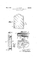
- Fig. 1 shows the front of a cabinet door.
- Fig. 2 is a side view of the cabi net.
- Fig. 3 is a cross section of a portion of the door showing the mirror and means for holding it in place and taken on the line 3, 3, of Fig. 1, and
- Fig. 4 is an enlarged view on the line 4, 4, of Fig. 3.
- Fig. 5 is a detail.
- A is the cabinet proper
- B is a door mounted on the cabinet proper by the hinge C.
- D is a mirror.
- the door B as shown consists of two metal plates having oppositely extending flanges telescoped together as shown in Fig. 3.
- E is a button having a screw threaded opening into which the screw Gr is adapted to engage.
- This button E as shown is cylindrical, although it may be of any desired shape either rectangular or may be an elongated button or of any fanciful shape.
- the button is provided with a slot extending across the button below the head and so arranged and of such form that it may extend over opposite surfaces of the mirror D.
- the slot in the button E is arranged so that the outer portion of the slot is beveled to correspond with the bevel on the mirror D, while the lower portion of the slot is arranged parallel to the lower side of the mirror D.
- This slot is preferably of such size that sufficient space is afforded to permit the insertion of the edge of the mirror and also a strip or pad J of felt or similar material forming a cushion against which the mirror is held by the head of the button E as clearly shown in Fig. 3.
- K is a plate of soft metal such as lead or other suitable material which is placed between the mirror and the adjacent portions of the button E as a protective for the mirror.
- H is a cup shaped washer arranged on the innerside of-the outer portion of the door B and as shown is spot welded at I to the inner side of the outer shell of the door B.
- the button E passes through'an opening in the shell of the door B and is held by the screw G, the head of which rests on the cup shaped washer H.
- This construction as will be seen-provides a mounting which, while fixedly holding the mirror in place, is sufiiciently resilient by reason ofthe cup shaped washer Hand the cushion J .to allow for jars to, or expansion and contraction of, either the mirror or the door, or metal parts of the door, without damage to themirror and at the same time provides for a ready circulationof air between the door and the back of the mirror thereby preventing the accumulation of moisture with the consequent damage to the silver backing of the mirror.
- a glass or mirror mounting fixture composed of a button, an opening arranged in the side of the button adapted to receive a glass or mirror, said opening having walls so arranged as to be substantially parallel with the sides of the glass or mirror adjacent to the walls and resilient means fixedly attached to and holding said button in place on a mirror support.
- a glass or mirror mounting fixture composed of a member having a slot in one side thereof into which a glass or mirror edge may be placed, said slot having one I side adapted to engage andregister with the surface of a mirror or glass and the opposite side of-said slot being arranged on the opposite side of a glass or mirroigand resilient means fixedly attached to and holding said *member in placeon a glass or mirror support.
- a support for glass, mirror or similar articles consisting of a foundation to which the article is to be attached, a member having a slot inione side thereof adapted to enclose a portion of the article on top edge and un derside, and resilient means for holding said member in place on the support whereby the article is held fixed to the support.
- a support for glass, mirroror similar articles consisting of a foundation to which the article is to be attached, a member having a slot in one side thereof adapted toenclose a portion of the article on top edge and underside, means arranged to provide a space between the support and the mirror and resilient means for holding said member in place on the support whereby the article is held fixed to the support.
- a support for glass, mirror or similar articles consisting of a foundation to which the article is to be attached, a member having a slot in one side thereof adapted to enclose a portion of the article on top edge-and underside, a cushion arranged to provide a spacebetween the support'andthe mirror'and resilient means for .holding said member in place on the support whereby the article is held fixed to the support.
- a glass or mirror mounting fixture composed of a button, an opening arranged in the side of the button adapted to receive a glass or mirror, means for resiliently holding said button in place on a mirror support, and a protecting cushion member between the glass or mirror and the button.
- a glassnor mirror mounting fixture composedio'f-a'button, an opening arranged in the side "of the button adapted to receive :a glass or mirror, means for resiliently holding said button in place on a mirror support, and a protecting'cushion member of a softer metal than the button between the glass or mirror and the button.
- a door having openings therethrough, a mirror, clip members extending through the openings in'thedoor from the back and having fingers engaging the mirror, and resilient cushion means fixedly attached to and reacting against the door-back and serving to exert thrust on the clip members behind the door to thereby clamp the 'mirror by the cllirp fingers snugly but yieldably against the c oor.
- a door having openings therethrough, a mirror, clip members having fingers extending'through the openings and 'engaging the mirror, cushion means fixedly at tached to and reacting against the door-back and against parts of the clip members, respectively, to snugly but yieldably clamp the mirror on the door by the clip member fingers, and a flanged cover plate detachably mounted on the :door-back and arranged to enclose the parts of the :clip members projecting backwardly from the door.
- a support for a glass, mirror, or a similar article consisting of a foundation to which the article is to be attached, an attaching device consisting of a body portion having means for overlapping the face of the article to be attached to the foundation, a shank portion provided with an opening, a screw threaded member adapted to engage said opening, resilientmeans fixedly secured to the foundation to engage with said member to resiliently hold an article in a fixed position on the foundation.
- a door having openings therethrough, a mirror, clip members extending through the openings in the door from the back and havingffingers engaging the mirror, and resilient cushion means fixedly secured to and reacting against the door-back to exert thrust on the clip members and means for adjusting the length of-said clip members.
Landscapes
- Rear-View Mirror Devices That Are Mounted On The Exterior Of The Vehicle (AREA)
Description
May 3, 1932. H. H. MILLER DEVICE FOR MOUNTING GLASS, MIRRORS, ETC
Filed Oct. 15, 1928 Patented May 3, 1932 UNITED STATES PATENT-OFFICE.
HARLEY n. MILLER, or MIDDLETOWN, OHIO, ASSIGNOB TO THE MIAMI cABINnr COMPANY, A conronArIoN or OHIO DEVICE FOR MOUNTING GLASS, MIRRORS, are.
Application filed October 15,1928. Serial No. 312,417.
My invention relates to improvement in devices for mounting glass, mirrors, etc. and devices therefor.
By my invention I provide a mounting for a mirror adapted to support same, to provide air space between a mirror and the article upon which it is mounted, to provide means whereby mirrors of any desired shape or out line may be readily mounted, also to provide for expansion and contraction of the mirror or mounting without danger of breakage.
In the drawings Fig. 1 shows the front of a cabinet door. Fig. 2 is a side view of the cabi net. Fig. 3 is a cross section of a portion of the door showing the mirror and means for holding it in place and taken on the line 3, 3, of Fig. 1, and Fig. 4 is an enlarged view on the line 4, 4, of Fig. 3. Fig. 5 is a detail.
In the drawings in which like letters refer to like parts, A is the cabinet proper, B is a door mounted on the cabinet proper by the hinge C. D is a mirror. The door B as shown consists of two metal plates having oppositely extending flanges telescoped together as shown in Fig. 3. E is a button having a screw threaded opening into which the screw Gr is adapted to engage. This button E as shown is cylindrical, although it may be of any desired shape either rectangular or may be an elongated button or of any fanciful shape. The button is provided with a slot extending across the button below the head and so arranged and of such form that it may extend over opposite surfaces of the mirror D. As
shown, the slot in the button E is arranged so that the outer portion of the slot is beveled to correspond with the bevel on the mirror D, while the lower portion of the slot is arranged parallel to the lower side of the mirror D. This slot is preferably of such size that sufficient space is afforded to permit the insertion of the edge of the mirror and also a strip or pad J of felt or similar material forming a cushion against which the mirror is held by the head of the button E as clearly shown in Fig. 3. K is a plate of soft metal such as lead or other suitable material which is placed between the mirror and the adjacent portions of the button E as a protective for the mirror. H is a cup shaped washer arranged on the innerside of-the outer portion of the door B and as shown is spot welded at I to the inner side of the outer shell of the door B. The button E passes through'an opening in the shell of the door B and is held by the screw G, the head of which rests on the cup shaped washer H. I
This construction as will be seen-provides a mounting which, while fixedly holding the mirror in place, is sufiiciently resilient by reason ofthe cup shaped washer Hand the cushion J .to allow for jars to, or expansion and contraction of, either the mirror or the door, or metal parts of the door, without damage to themirror and at the same time provides for a ready circulationof air between the door and the back of the mirror thereby preventing the accumulation of moisture with the consequent damage to the silver backing of the mirror.
, Claims: 7
1. A glass or mirror mounting fixture composed of a button, an opening arranged in the side of the button adapted to receive a glass or mirror, said opening having walls so arranged as to be substantially parallel with the sides of the glass or mirror adjacent to the walls and resilient means fixedly attached to and holding said button in place on a mirror support. 2. A glass or mirror mounting fixture composed of a member having a slot in one side thereof into which a glass or mirror edge may be placed, said slot having one I side adapted to engage andregister with the surface of a mirror or glass and the opposite side of-said slot being arranged on the opposite side of a glass or mirroigand resilient means fixedly attached to and holding said *member in placeon a glass or mirror support. V 3. A support for glass, mirror or similar articles consisting of a foundation to which the article is to be attached, a member having a slot inione side thereof adapted to enclose a portion of the article on top edge and un derside, and resilient means for holding said member in place on the support whereby the article is held fixed to the support.
- 4. A support for glass, mirroror similar articles consisting of a foundation to which the article is to be attached, a member having a slot in one side thereof adapted toenclose a portion of the article on top edge and underside, means arranged to provide a space between the support and the mirror and resilient means for holding said member in place on the support whereby the article is held fixed to the support.
5. A support for glass, mirror or similar articles consisting of a foundation to which the article is to be attached, a member having a slot in one side thereof adapted to enclose a portion of the article on top edge-and underside, a cushion arranged to provide a spacebetween the support'andthe mirror'and resilient means for .holding said member in place on the support whereby the article is held fixed to the support.
:6. A glass or mirror mounting fixture composed of a button, an opening arranged in the side of the button adapted to receive a glass or mirror, means for resiliently holding said button in place on a mirror support, and a protecting cushion member between the glass or mirror and the button.
7. A glassnor mirror mounting fixture composedio'f-a'button, an opening arranged in the side "of the button adapted to receive :a glass or mirror, means for resiliently holding said button in place on a mirror support, and a protecting'cushion member of a softer metal than the button between the glass or mirror and the button.
8. A door having openings therethrough, a mirror, clip members extending through the openings in'thedoor from the back and having fingers engaging the mirror, and resilient cushion means fixedly attached to and reacting against the door-back and serving to exert thrust on the clip members behind the door to thereby clamp the 'mirror by the cllirp fingers snugly but yieldably against the c oor.
9. A door having openings therethrough, a mirror, clip members having fingers extending'through the openings and 'engaging the mirror, cushion means fixedly at tached to and reacting against the door-back and against parts of the clip members, respectively, to snugly but yieldably clamp the mirror on the door by the clip member fingers, and a flanged cover plate detachably mounted on the :door-back and arranged to enclose the parts of the :clip members projecting backwardly from the door.
10. A support for a glass, mirror, or a similar article consisting of a foundation to which the article is to be attached, an attaching device consisting of a body portion having means for overlapping the face of the article to be attached to the foundation, a shank portion provided with an opening, a screw threaded member adapted to engage said opening, resilientmeans fixedly secured to the foundation to engage with said member to resiliently hold an article in a fixed position on the foundation.
11. A door having openings therethrough, a mirror, clip members extending through the openings in the door from the back and havingffingers engaging the mirror, and resilient cushion means fixedly secured to and reacting against the door-back to exert thrust on the clip members and means for adjusting the length of-said clip members.
Priority Applications (1)
| Application Number | Priority Date | Filing Date | Title |
|---|---|---|---|
| US312417A US1856923A (en) | 1928-10-15 | 1928-10-15 | Device for mounting glass, mirrors, etc. |
Applications Claiming Priority (1)
| Application Number | Priority Date | Filing Date | Title |
|---|---|---|---|
| US312417A US1856923A (en) | 1928-10-15 | 1928-10-15 | Device for mounting glass, mirrors, etc. |
Publications (1)
| Publication Number | Publication Date |
|---|---|
| US1856923A true US1856923A (en) | 1932-05-03 |
Family
ID=23211338
Family Applications (1)
| Application Number | Title | Priority Date | Filing Date |
|---|---|---|---|
| US312417A Expired - Lifetime US1856923A (en) | 1928-10-15 | 1928-10-15 | Device for mounting glass, mirrors, etc. |
Country Status (1)
| Country | Link |
|---|---|
| US (1) | US1856923A (en) |
Cited By (2)
| Publication number | Priority date | Publication date | Assignee | Title |
|---|---|---|---|---|
| US4394000A (en) * | 1981-01-02 | 1983-07-19 | Kurtz Thomas D | Metal mirror mounting clip |
| US4724643A (en) * | 1986-07-29 | 1988-02-16 | Tenn-Tex Plastics, Inc. | Retainer clip with resilient pad |
-
1928
- 1928-10-15 US US312417A patent/US1856923A/en not_active Expired - Lifetime
Cited By (2)
| Publication number | Priority date | Publication date | Assignee | Title |
|---|---|---|---|---|
| US4394000A (en) * | 1981-01-02 | 1983-07-19 | Kurtz Thomas D | Metal mirror mounting clip |
| US4724643A (en) * | 1986-07-29 | 1988-02-16 | Tenn-Tex Plastics, Inc. | Retainer clip with resilient pad |
Similar Documents
| Publication | Publication Date | Title |
|---|---|---|
| US6829863B2 (en) | Door jamb protector | |
| IT1107686B (en) | REFINEMENT IN THE OPHTHALMIC SUPPLIER PACKAGES | |
| US2710694A (en) | Combination holder and closure for containers | |
| DE59901719D1 (en) | BRACKET FOR AT LEAST ONE COMPACT DISK | |
| NL7602178A (en) | DEVICE FOR SQUIPPING MOP AND THE LIKE. | |
| US1856923A (en) | Device for mounting glass, mirrors, etc. | |
| DE3483238D1 (en) | DEVICE FOR CONTROLLING THE STAND. | |
| US1863633A (en) | Name plate | |
| US2143608A (en) | Frame | |
| US3482796A (en) | Toilet paper holder | |
| IT1066640B (en) | IMPROVEMENT IN THE APPLIANCES AND PROCEDURES FOR BENDING GLASS SHEETS | |
| IT1075183B (en) | IMPROVEMENT IN THE APPLIANCES FOR SUPPORTING AND CONVEYING GLASS SHEETS | |
| US2881544A (en) | Picture supporting means | |
| US2748513A (en) | Label holder for filing cabinet drawers | |
| NL7805648A (en) | DEVICE FOR THE MOVEMENT OF HOLDERS. | |
| US2031068A (en) | Refrigerator door | |
| US1649891A (en) | Vanity case | |
| JPS52136493A (en) | Device for attaching polishing buff or the like | |
| DK153689D0 (en) | DEVICE FOR LOGO OR MARKING DETAILS AT THE APPLIANCE CABINET OR CAR CAR BODY | |
| NL7903812A (en) | HOLDERS FOR BEVERAGES AND THE LIKE. | |
| DE3575600D1 (en) | GASKET STRIP FRAME FOR FURNITURE LIKE REFRIGERATORS AND THE LIKE. | |
| IT8060471V0 (en) | GLASSES AND FRAME WITH DEVICE FOR EYE EDGES. | |
| US1581658A (en) | Shelf support | |
| US1421392A (en) | Combination comb case | |
| IT1086127B (en) | BASE PLATE AND ADJUSTMENT PLATE FOR A HINGE ARM FOR FURNITURE SURROUNDING THE BASE PLATE |