US1856921A - Hat form - Google Patents
Hat form Download PDFInfo
- Publication number
- US1856921A US1856921A US417369A US41736929A US1856921A US 1856921 A US1856921 A US 1856921A US 417369 A US417369 A US 417369A US 41736929 A US41736929 A US 41736929A US 1856921 A US1856921 A US 1856921A
- Authority
- US
- United States
- Prior art keywords
- hat
- members
- crossed
- hat form
- loop
- Prior art date
- Legal status (The legal status is an assumption and is not a legal conclusion. Google has not performed a legal analysis and makes no representation as to the accuracy of the status listed.)
- Expired - Lifetime
Links
- 238000010276 construction Methods 0.000 description 2
Images
Classifications
-
- A—HUMAN NECESSITIES
- A42—HEADWEAR
- A42B—HATS; HEAD COVERINGS
- A42B1/00—Hats; Caps; Hoods
- A42B1/002—External devices or supports adapted to retain the shape of hats, caps or hoods
Definitions
- This invention relates to hat forms, and more particularly to forms utilized for retaining the shape of a hat.
- a hat form which when applied to the interior of a hat will cause the hat to conform to its original shape; to provide means by which the hat form may be hung up; to provide a hat form which will permit the same to be partially collapsed when not in use, to provide a hat form which may be expanded or contracted to fit hats of various sizes; to secure simplicity of construction, and to obtain other advantages and results as may be brought out in the following description.
- Figure 1 is a front elevation of a hat form in an expanded position
- Figure 2 is a view looking upward from the underside of Figure 1, and
- Figure 3 is a similar view to Fig. 2, and with the crossed members contracted.
- each of the crossed members 5, 6 preferably are turned inwardly toward each other and overlap, thus providing overlapping end portions 7, 7 for one of said crossed members 5, and overlapping end portions 8, 8 of the member 6. It will be observed that these overlapping portions 7 7 and 8, 8 cross each other, and such crossing is at a point midwaybetween the legs of the U-shaped members. At this point of crossing the several portions of the crossed members are secured together by suitable pivoting means, such as a rivet 9. Likewise, where the U- shaped members cross at the curved part of the said members, the same are likewise pivotally secured together by suitable pivoting means, such as a rivet 10.
- pivots 9 and 10 are preferably in substantial alignment so that the said members may be 50 swung readily upon those pivots about a common axis.
- one of said crossed members is smaller in diameter than the other member and pivoted next the inside surface of the other member, both at the curved part thereof, and at the crossed member. This construction will therefore enable the smaller member 6 to be rotated into registration with the outer member 5 so as to lie entirely within the same, as shown in Figure 3.
- the members 5, 6 When the device is to be used in a hat, the members 5, 6 are swung on their pivots 9 and 10 to stand substantially at right angles'to each other at which time it can be inserted in a hat, and hold the hat distended so to conform to its original shape. 7
- the crossed members 5 and 6 have been shown providing overlapping portions 7 7 and 8, 8, the portions of each member having a restricted longitudinal freedom of movement so as to permit the legs of each U-shaped member to spread a limited amount as shown in dotted lines in Figure 1.
- the overlapping portions are each provided with longitudinal slots 11 through which the pivoting rivet 9 is passed. The length of these slots will obviously determine the amount of the expansion which the U-shaped members are allowed.
- members of spring material the same can be normally expanded as shown by the dotted lines of Figure 1, and yet may be pressed inwardly so the legs will swing towards each other when the form is applied to a hat of smaller dimension.
- a hook 12 pivotally carried from a suitable part of the form.
- a loop 13 is pivoted fiatwise with respect to one of the overlapping portions 7 of the outer crossed member 5.
- This loop is shown as made from a short piece of strip material with the overlapping ends thereof secured by a rivet 14 which acts as a pivot.
- the loop forms a bearing for the hinged portion of the hook 12 which can therefore swing in a plane at right angles to the plane of the loop.
- the outer end of the hook provides a suitable crook or loop 15 by which the same can be caught on a nail or other supporting device.
- the double pivotal attachment of the hook 6 to the crossed members enables the form to be hung at any desired angle to meet the requirements or desires of the person utilizing the same.
- WVhileJitis preferableto hang the form, it nevertheless can be likewise placed 10 in an upright position.
- the Crossed he t 11enot e a atlfiatianappropriate distance from the pivoting of the hook thereto, such that the crook or loop 15 can be swung around and engaged in said 15 notch thus securing the parts together when not. in use. as clearly shown in Figure 3.
- a device as characterized, a hat form comprising crossed members, means for pivoting said crossed members together, and 25 means for hanging the form up from one of its crossed members, one of said members being rotatable to. be positioned within the other, said hanging means cooperating. with the folded members for retaining the same 351, in folded position.
Landscapes
- Sewing Machines And Sewing (AREA)
Description
y 1932- M. LOWENTHAL ET AL 3 5 HAT FORM Filed Dec. 30, 1929 v -lg m Emma bow Milton, Lowenihai Jaco Kwlz/z'n/ fibair Wen/3 Patented May 3, 1932 UNITED STATES PATENT OFFICE MILTON LOWENTHAL AND JACOB KALVIN, OF NEW YORK, N. Y.
HAT FORM Application filed December 30, 1929. Serial No. 417,369.
This invention relates to hat forms, and more particularly to forms utilized for retaining the shape of a hat.
Among the principal objects of the lnvention are: to provide a hat form which when applied to the interior of a hat will cause the hat to conform to its original shape; to provide means by which the hat form may be hung up; to provide a hat form which will permit the same to be partially collapsed when not in use, to provide a hat form which may be expanded or contracted to fit hats of various sizes; to secure simplicity of construction, and to obtain other advantages and results as may be brought out in the following description.
In the drawings:
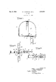
Figure 1 is a front elevation of a hat form in an expanded position;
Figure 2 is a view looking upward from the underside of Figure 1, and
Figure 3 is a similar view to Fig. 2, and with the crossed members contracted.
Description In the specific embodiment of the invention illustrated in said drawings, we have shown a hat form comprising a pair of crossed members 5, preferably of a spring strip material bent into U-shape.
The ends of each of the crossed members 5, 6 preferably are turned inwardly toward each other and overlap, thus providing overlapping end portions 7, 7 for one of said crossed members 5, and overlapping end portions 8, 8 of the member 6. It will be observed that these overlapping portions 7 7 and 8, 8 cross each other, and such crossing is at a point midwaybetween the legs of the U-shaped members. At this point of crossing the several portions of the crossed members are secured together by suitable pivoting means, such as a rivet 9. Likewise, where the U- shaped members cross at the curved part of the said members, the same are likewise pivotally secured together by suitable pivoting means, such as a rivet 10. The axes of these pivots 9 and 10 are preferably in substantial alignment so that the said members may be 50 swung readily upon those pivots about a common axis. Furthermore, one of said crossed members is smaller in diameter than the other member and pivoted next the inside surface of the other member, both at the curved part thereof, and at the crossed member. This construction will therefore enable the smaller member 6 to be rotated into registration with the outer member 5 so as to lie entirely within the same, as shown in Figure 3.
When the device is to be used in a hat, the members 5, 6 are swung on their pivots 9 and 10 to stand substantially at right angles'to each other at which time it can be inserted in a hat, and hold the hat distended so to conform to its original shape. 7
In order that the devicemay be utilized in hats of different sizes, the crossed members 5 and 6 have been shown providing overlapping portions 7 7 and 8, 8, the portions of each member having a restricted longitudinal freedom of movement so as to permit the legs of each U-shaped member to spread a limited amount as shown in dotted lines in Figure 1. As one means for accomplishing this purpose the overlapping portions are each provided with longitudinal slots 11 through which the pivoting rivet 9 is passed. The length of these slots will obviously determine the amount of the expansion which the U-shaped members are allowed. By utilizing members of spring material, the same can be normally expanded as shown by the dotted lines of Figure 1, and yet may be pressed inwardly so the legs will swing towards each other when the form is applied to a hat of smaller dimension.
In order that the form may be hung up with or without a hat applied thereto, we have shown a hook 12 pivotally carried from a suitable part of the form. As herein shown, a loop 13 is pivoted fiatwise with respect to one of the overlapping portions 7 of the outer crossed member 5. This loop is shown as made from a short piece of strip material with the overlapping ends thereof secured by a rivet 14 which acts as a pivot. The loop forms a bearing for the hinged portion of the hook 12 which can therefore swing in a plane at right angles to the plane of the loop. The outer end of the hook provides a suitable crook or loop 15 by which the same can be caught on a nail or other supporting device.
The double pivotal attachment of the hook 6 to the crossed members enables the form to be hung at any desired angle to meet the requirements or desires of the person utilizing the same. WVhileJitis preferableto hang the form, it nevertheless can be likewise placed 10 in an upright position. Preferably the Crossed he t 11enot e a atlfiatianappropriate distance from the pivoting of the hook thereto, such that the crook or loop 15 can be swung around and engaged in said 15 notch thus securing the parts together when not. in use. as clearly shown in Figure 3. Therefore, when the device is in aclosed position it may then be placed ona shelf or other fiat surface taking minimum space the e We claim 1 In, a device as characterized, a hat form comprising crossed members, means for pivoting said crossed members together, and 25 means for hanging the form up from one of its crossed members, one of said members being rotatable to. be positioned within the other, said hanging means cooperating. with the folded members for retaining the same 351, in folded position.
MILTON; LOWENTHLAL. AC K L I R
Priority Applications (1)
| Application Number | Priority Date | Filing Date | Title |
|---|---|---|---|
| US417369A US1856921A (en) | 1929-12-30 | 1929-12-30 | Hat form |
Applications Claiming Priority (1)
| Application Number | Priority Date | Filing Date | Title |
|---|---|---|---|
| US417369A US1856921A (en) | 1929-12-30 | 1929-12-30 | Hat form |
Publications (1)
| Publication Number | Publication Date |
|---|---|
| US1856921A true US1856921A (en) | 1932-05-03 |
Family
ID=23653732
Family Applications (1)
| Application Number | Title | Priority Date | Filing Date |
|---|---|---|---|
| US417369A Expired - Lifetime US1856921A (en) | 1929-12-30 | 1929-12-30 | Hat form |
Country Status (1)
| Country | Link |
|---|---|
| US (1) | US1856921A (en) |
Cited By (6)
| Publication number | Priority date | Publication date | Assignee | Title |
|---|---|---|---|---|
| US2713444A (en) * | 1954-05-11 | 1955-07-19 | Dombrowski Eugene Joseph | Hat stretcher |
| US3036698A (en) * | 1960-08-16 | 1962-05-29 | Container Corp | Hat holder |
| US4438693A (en) * | 1982-11-15 | 1984-03-27 | R. Jennings Manufacturing Company, Inc. | Silk screen printing onto the front panel of a cap |
| USRE32731E (en) * | 1982-11-15 | 1988-08-16 | R. Jennings Manufacturing Co., Inc. | Silk screen printing onto the front panel of a cap |
| US5014614A (en) * | 1989-06-30 | 1991-05-14 | Thieme Gaylord G | Cap printing device and method |
| US11974622B1 (en) * | 2022-03-10 | 2024-05-07 | Timothy N Caveny | Hat form |
-
1929
- 1929-12-30 US US417369A patent/US1856921A/en not_active Expired - Lifetime
Cited By (6)
| Publication number | Priority date | Publication date | Assignee | Title |
|---|---|---|---|---|
| US2713444A (en) * | 1954-05-11 | 1955-07-19 | Dombrowski Eugene Joseph | Hat stretcher |
| US3036698A (en) * | 1960-08-16 | 1962-05-29 | Container Corp | Hat holder |
| US4438693A (en) * | 1982-11-15 | 1984-03-27 | R. Jennings Manufacturing Company, Inc. | Silk screen printing onto the front panel of a cap |
| USRE32731E (en) * | 1982-11-15 | 1988-08-16 | R. Jennings Manufacturing Co., Inc. | Silk screen printing onto the front panel of a cap |
| US5014614A (en) * | 1989-06-30 | 1991-05-14 | Thieme Gaylord G | Cap printing device and method |
| US11974622B1 (en) * | 2022-03-10 | 2024-05-07 | Timothy N Caveny | Hat form |
Similar Documents
| Publication | Publication Date | Title |
|---|---|---|
| US2232249A (en) | Garment hanger | |
| US1856921A (en) | Hat form | |
| US1501807A (en) | Hat-supporting hook | |
| US2137700A (en) | Garment hanger | |
| US2509754A (en) | Garment hanger | |
| US2573622A (en) | Garment hanger of the folding type | |
| US2209864A (en) | Garment hanger | |
| US2957669A (en) | Collapsible garment stand | |
| US2513980A (en) | Coat hanger | |
| US1955995A (en) | Collapsible garment hanger | |
| US2295736A (en) | Foldable rack | |
| US2720718A (en) | Map and blueprint holder | |
| US1682626A (en) | Garment hanger | |
| US1458114A (en) | Garment hanger | |
| US2119934A (en) | Garment hanger | |
| US1700666A (en) | Embroidery frame | |
| US2259692A (en) | Automatic self-adjusting trousers hanger and creaser | |
| US325394A (en) | Reel for holding wire in the coil | |
| US1616870A (en) | Clothes hanger | |
| US2303095A (en) | Garment supporting and display device | |
| US2789703A (en) | Costumer | |
| US2782969A (en) | Folding garment hanger | |
| US1836935A (en) | Foldable wardrobe appliance | |
| US1783709A (en) | Garment hanger | |
| US1573649A (en) | Garment hanger |