US1856919A - Iceless cooler - Google Patents
Iceless cooler Download PDFInfo
- Publication number
- US1856919A US1856919A US459389A US45938930A US1856919A US 1856919 A US1856919 A US 1856919A US 459389 A US459389 A US 459389A US 45938930 A US45938930 A US 45938930A US 1856919 A US1856919 A US 1856919A
- Authority
- US
- United States
- Prior art keywords
- carrier
- cooler
- casing
- motor
- shaft
- Prior art date
- Legal status (The legal status is an assumption and is not a legal conclusion. Google has not performed a legal analysis and makes no representation as to the accuracy of the status listed.)
- Expired - Lifetime
Links
- 239000000428 dust Substances 0.000 description 2
- 230000005484 gravity Effects 0.000 description 2
- 230000000284 resting effect Effects 0.000 description 2
- 239000000969 carrier Substances 0.000 description 1
- 238000001816 cooling Methods 0.000 description 1
- 230000001419 dependent effect Effects 0.000 description 1
- 230000000994 depressogenic effect Effects 0.000 description 1
- 238000009408 flooring Methods 0.000 description 1
- 238000009434 installation Methods 0.000 description 1
Images

Classifications
-
- F—MECHANICAL ENGINEERING; LIGHTING; HEATING; WEAPONS; BLASTING
- F25—REFRIGERATION OR COOLING; COMBINED HEATING AND REFRIGERATION SYSTEMS; HEAT PUMP SYSTEMS; MANUFACTURE OR STORAGE OF ICE; LIQUEFACTION SOLIDIFICATION OF GASES
- F25D—REFRIGERATORS; COLD ROOMS; ICE-BOXES; COOLING OR FREEZING APPARATUS NOT OTHERWISE PROVIDED FOR
- F25D9/00—Devices not associated with refrigerating machinery and not covered by groups F25D1/00 - F25D7/00; Combinations of devices covered by two or more of the groups F25D1/00 - F25D7/00
Definitions
- This invention relatesto improvements in refrigerating apparatus for domestic use and more particularly to an iceless cooler of that type adapted to be positioned below the sur- I face of the earth and dependent upon the earth temperature for its cooling properties.
- Coolers of this class comprise carriers or dumb waiters that are raised and lowered to receive and deliver their contents and frequently parts are broken or damaged through carelessness or accident in operation.
- present cooler provides an automatic governor that regulates or controls the speed of the carrier upon its return to its normal po- 1: sition after each delivery.
- the cooler is adapted for either manual operation or to be driven by a motor. Means for supplying fresh air to the cooler each time it makes a delivery are provided.
- the cooler is compact in'assembly and not complicated in structure so that installation in a very small space, such as in a corner of a pantry or kitchen, is possible.
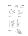
- Fig. 2 is an enlarged fragmentary sectional view of the carrier.
- Fig. 3 is a similar view of the lower end of the cooler showing how it is imbedded in the earth and provided with air supply means.
- Fig. 4 is an enlarged fragmentary sectional detail view of the cooler illustrating the governor for controlling the descent of the carr1er.
- Fig. 5 is a cross sectional view taken on the line 55 of Fig. 2.
- Fig. 6 is an enlarged vertical sectional view of Fig. 5.
- Fig. 7 is a fragmentary view of the cooler provided with a motor.
- Fig. 8 is a side view of Fig. 7.
- the cooler comprises the carrier that is 1930. Serial No. 459,389.
- Raising and lowering the carrier in its casing causes air to be drawn into and forced out of the casing.
- Raising and lowering mechanism for the carrier are provided above the ground.
- the reference numeral 1 denotes the flooring of a basement or house resting upon the surface of the ground 2. Extending snugly through an opening in the floor and into the ground is the cylindrical casing 3 having the contracted lower termination 4 forming an air well. Surrounding the upper end of the casing and resting upon the floor is the dust collar 5 integral with the annular band 6 that snugly encompasses the casing and receives the cover 7. An air pipe 8 tapped into the air Well 4 of the casing extends upwardly through the floor 1 and terminates in the intake head 9 provided with a screen for exeluding dust and dirt from the pipe.
- the carrier Received within that portion of the casing 3 above the air Well is the carrier having the base 10 encompassed by the ring 11, similar to a piston ring, which meets the inner face of the casing and, as the carrier is raised and lowered, causes a suction to draw in air or expel the same through the air pipe 8.
- Three rods 12 secured to the carrier base l0 extend perpendicularly to the yoke ring 13 at the upper end of the carrier to which said rods are secured, said yoke ring having a diametrical cross bar 14, the upper end of the carrier receiving, together with the said band 6, the cover 7.
- the carrier includes a plurality of trays 16 for receiving the food, each tray comprising a bottom and an integral annular body wall formed with a top inwardly curved flange 17 formed with three notches 18 to provide clearance for the hooks 19 carried by the rods 12, the space between the notches corresponding 9.. to that between the hooks in a horizontal plane so that the three books may be passed simultaneously through the three notches and the tray then turned slightly to cause the hooks to engage with the flange 17, as shown in Fig.
- Each tray (i, and support the tray.
- a plurality of trays are provided spaced apart in the carrier.
- Each tray is adjustable horizontally to permit engagement with and release from its hooks, and removable.
- One end of a cable extends through a perforation in the cover 7 and is secured to the cross bar 14, said cable extending up through a cable guide 21, carried by the support post 22 that rests upon the floor and is secured to the ceiling 23, and over the sheave 24 to the spool 25.
- the sheave is supported at one end of the arm 26 adjustably secured to the post 22.
- the shaft 27 of the spool is journaled in and extends through the housing 28 secured to the post 22, said shaft 27 having fast thereupon, within said housing, a non-circular disc 29 which is received concentrically within the worm gear 30, said gear and disc fitting loosely to each other so that normally the disc may rotate freely with respect to the gear.
- the bore in the worm gear is formed with a notch 31 and in the space between the flat edge 32 of the disc and the wall of the bore a dog 33 is arranged and-kept yieldingly in frictional engagement with the wall of the bore by the spring 34 secured to the fiat edge 32.
- This gear is in mesh with the worm 35 mounted for rotation inside the housing 28, one end 36 of the worm shaft extending beyond the housing and carrying a bushing 37 encompassed by a clamping ring 38 secured to the housing, said ring carrying the set screw 39 whereby said ring 38 may be clamped, in the manner of a brake, against the buslr ing to retard the rotation thereof together with the shaft 36.
- the clamping ring 38 may be of any type, such as a split ring with its ends engaged by the screw 39 so that tightening the screw will force one end of the ring frietionally against the bushing to act as a brake.
- the shaft 27 at one end is provided with the handle 40 by means of which it may be rotated to wind the cable upon the spool 25 and raise the carrier, with the trays, out of the casing 3. In this movement the shaft 27 is rotated in a direction to turn the disc 29 independently of the worm 35.
- the carrier comprising the base 10, rods 12, ring 13 and trays 16
- the trays may be manually filled or unloaded and the carrier then returned to the casing.
- This movement takes place when the handle 40 is released, with the brake off.
- the weight of the carrier will unwind the cable from the spool and rotate the shaft 27 in a direction to rotate the worm gear and the worm
- the latter will serve as a governor to check an otherwise too rapid descent of the carrier into the casing. This governor feature we vents damage to the carrier or its contents.
- the cable passing through the center of the cover 7 will automatically apply the same to the casing as the carrier descends.
- the shaft of the spool 25 is connected to the shaft of a motor 41 that is supported by bracket 42 fastened to the post 22.
- a switch box -13 that carries a switch for turning on the motor.
- the long lever 44 Connected to this switch is the long lever 44 that extends obliquely downward and when the .arm is depressed manually it throws the switch to-start the motor.
- the free end of the arm 44 is now in the path of movement of the carrier which, w-hen raised bythe motor, will strike said armand raise same and so automatically open the switchand shut off the motor.
- the brake isa-pplied before the motor is started sothat return ofthe carrier to the casing 3 through gravity after themotor has stopped prevented. VV hen the carrier is to be returned the brake. is released and the weight of the carrier will reverse the motor and permit the carrier to lower at moderate speed.
- hat is claimed is In an iceless cooler, a casing adapted to be positioned beneath the surface of the earth, a carrieraadapted. for movement into. and out of said casing, said carrier being adapted to move into said casing through gravity after each removal therefrom, a spool, a cable con necting said carrier to said spool and adapted to he wound upon the latter to raise said carrier,.-a.motor for said spool, a worm gear loose upon the motor shaft, means connecting said worm gear and motor shaft for causing them to move together when said motor shaft moves in one direction, a worm in mesh with said worm gear, anda brakefor said worm.
Landscapes
- Engineering & Computer Science (AREA)
- Chemical & Material Sciences (AREA)
- Combustion & Propulsion (AREA)
- Physics & Mathematics (AREA)
- Mechanical Engineering (AREA)
- Thermal Sciences (AREA)
- General Engineering & Computer Science (AREA)
- Transmission Devices (AREA)
Description
May 3, 1932. LANDEN 1,856,919
ICELESS COOLER Filed June 5, 1930 2 Sheets-Sheet 1 a. (LA
B. LANDEN ICELES S COOLER May 3, 1932.
Filed June 5, 1930 2 Sheets-Sheet 2 Patented May 3, 1932 assen PATET BERNARD LANDEN, F OAKLAND, NEBRASKA ICELESS COOLER Application filed June 5,
This invention relatesto improvements in refrigerating apparatus for domestic use and more particularly to an iceless cooler of that type adapted to be positioned below the sur- I face of the earth and dependent upon the earth temperature for its cooling properties.
Coolers of this class comprise carriers or dumb waiters that are raised and lowered to receive and deliver their contents and frequently parts are broken or damaged through carelessness or accident in operation. The
present cooler provides an automatic governor that regulates or controls the speed of the carrier upon its return to its normal po- 1: sition after each delivery. I
The cooler is adapted for either manual operation or to be driven by a motor. Means for supplying fresh air to the cooler each time it makes a delivery are provided. The cooler is compact in'assembly and not complicated in structure so that installation in a very small space, such as in a corner of a pantry or kitchen, is possible.
More specifically the invention consists in the combination and arrangement of parts to be hereinafter fully described, pointed out in the claim and illustrated in the accompanying drawings which form a part of this application for patent and in which- Fig. l'is a view of the complete cooler in elevation illustratingits application.
Fig. 2 is an enlarged fragmentary sectional view of the carrier.
Fig. 3 is a similar view of the lower end of the cooler showing how it is imbedded in the earth and provided with air supply means.
Fig. 4 is an enlarged fragmentary sectional detail view of the cooler illustrating the governor for controlling the descent of the carr1er.
Fig. 5 is a cross sectional view taken on the line 55 of Fig. 2.
Fig. 6 is an enlarged vertical sectional view of Fig. 5.
Fig. 7 is a fragmentary view of the cooler provided with a motor.
Fig. 8 is a side view of Fig. 7.
Like reference characters denote corresponding parts throughout the several views.
The cooler comprises the carrier that is 1930. Serial No. 459,389.
disposed normally beneath the surface of the earth in a casing, the lower end of the casing being supplied with air furnished by a pipe leading from a point above the surface of the ground. Raising and lowering the carrier in its casing causes air to be drawn into and forced out of the casing. Raising and lowering mechanism for the carrier are provided above the ground.
The reference numeral 1 denotes the flooring of a basement or house resting upon the surface of the ground 2. Extending snugly through an opening in the floor and into the ground is the cylindrical casing 3 having the contracted lower termination 4 forming an air well. Surrounding the upper end of the casing and resting upon the floor is the dust collar 5 integral with the annular band 6 that snugly encompasses the casing and receives the cover 7. An air pipe 8 tapped into the air Well 4 of the casing extends upwardly through the floor 1 and terminates in the intake head 9 provided with a screen for exeluding dust and dirt from the pipe.
Received within that portion of the casing 3 above the air Well is the carrier having the base 10 encompassed by the ring 11, similar to a piston ring, which meets the inner face of the casing and, as the carrier is raised and lowered, causes a suction to draw in air or expel the same through the air pipe 8.
Three rods 12 secured to the carrier base l0 extend perpendicularly to the yoke ring 13 at the upper end of the carrier to which said rods are secured, said yoke ring having a diametrical cross bar 14, the upper end of the carrier receiving, together with the said band 6, the cover 7.
The carrier includes a plurality of trays 16 for receiving the food, each tray comprising a bottom and an integral annular body wall formed with a top inwardly curved flange 17 formed with three notches 18 to provide clearance for the hooks 19 carried by the rods 12, the space between the notches corresponding 9.. to that between the hooks in a horizontal plane so that the three books may be passed simultaneously through the three notches and the tray then turned slightly to cause the hooks to engage with the flange 17, as shown in Fig.
(i, and support the tray. A plurality of trays are provided spaced apart in the carrier. Each tray is adjustable horizontally to permit engagement with and release from its hooks, and removable.
One end of a cable extends through a perforation in the cover 7 and is secured to the cross bar 14, said cable extending up through a cable guide 21, carried by the support post 22 that rests upon the floor and is secured to the ceiling 23, and over the sheave 24 to the spool 25. The sheaveis supported at one end of the arm 26 adjustably secured to the post 22.
Referring now to Figs. 1 to 6 inclusive, the shaft 27 of the spool is journaled in and extends through the housing 28 secured to the post 22, said shaft 27 having fast thereupon, within said housing, a non-circular disc 29 which is received concentrically within the worm gear 30, said gear and disc fitting loosely to each other so that normally the disc may rotate freely with respect to the gear.
The bore in the worm gear is formed with a notch 31 and in the space between the flat edge 32 of the disc and the wall of the bore a dog 33 is arranged and-kept yieldingly in frictional engagement with the wall of the bore by the spring 34 secured to the fiat edge 32. When the shaft and disc rotate in one direc tion they will rotate independently of the worm gear as the dog will pass over the notch 31. When the direction of rotation is reversed, however, the dog will enter the notch 31 and cause rotation of the worm gear. This gear is in mesh with the worm 35 mounted for rotation inside the housing 28, one end 36 of the worm shaft extending beyond the housing and carrying a bushing 37 encompassed by a clamping ring 38 secured to the housing, said ring carrying the set screw 39 whereby said ring 38 may be clamped, in the manner of a brake, against the buslr ing to retard the rotation thereof together with the shaft 36. The clamping ring 38 may be of any type, such as a split ring with its ends engaged by the screw 39 so that tightening the screw will force one end of the ring frietionally against the bushing to act as a brake.
The shaft 27 at one end is provided with the handle 40 by means of which it may be rotated to wind the cable upon the spool 25 and raise the carrier, with the trays, out of the casing 3. In this movement the shaft 27 is rotated in a direction to turn the disc 29 independently of the worm 35. When the carrier, comprising the base 10, rods 12, ring 13 and trays 16, is raised out of the casing the trays may be manually filled or unloaded and the carrier then returned to the casing. This movement takes place when the handle 40 is released, with the brake off. The weight of the carrier will unwind the cable from the spool and rotate the shaft 27 in a direction to rotate the worm gear and the worm The latter will serve as a governor to check an otherwise too rapid descent of the carrier into the casing. This governor feature we vents damage to the carrier or its contents. The cable passing through the center of the cover 7 will automatically apply the same to the casing as the carrier descends.
Referring now to Figs. 7 and 8, the shaft of the spool 25 is connected to the shaft of a motor 41 that is supported by bracket 42 fastened to the post 22. Mounted to the inner end of the cable guide 21 is a switch box -13 that carries a switch for turning on the motor. Connected to this switch is the long lever 44 that extends obliquely downward and when the .arm is depressed manually it throws the switch to-start the motor. The free end of the arm 44 is now in the path of movement of the carrier which, w-hen raised bythe motor, will strike said armand raise same and so automatically open the switchand shut off the motor. The brake isa-pplied before the motor is started sothat return ofthe carrier to the casing 3 through gravity after themotor has stopped prevented. VV hen the carrier is to be returned the brake. is released and the weight of the carrier will reverse the motor and permit the carrier to lower at moderate speed.
hat is claimed is In an iceless cooler, a casing adapted to be positioned beneath the surface of the earth, a carrieraadapted. for movement into. and out of said casing, said carrier being adapted to move into said casing through gravity after each removal therefrom, a spool, a cable con necting said carrier to said spool and adapted to he wound upon the latter to raise said carrier,.-a.motor for said spool, a worm gear loose upon the motor shaft, means connecting said worm gear and motor shaft for causing them to move together when said motor shaft moves in one direction, a worm in mesh with said worm gear, anda brakefor said worm.
In testimony that I claim the foregoing as my own I have hereto aflixed my signature.
' BERNARD L'ANDEN.
Priority Applications (1)
| Application Number | Priority Date | Filing Date | Title |
|---|---|---|---|
| US459389A US1856919A (en) | 1930-06-05 | 1930-06-05 | Iceless cooler |
Applications Claiming Priority (1)
| Application Number | Priority Date | Filing Date | Title |
|---|---|---|---|
| US459389A US1856919A (en) | 1930-06-05 | 1930-06-05 | Iceless cooler |
Publications (1)
| Publication Number | Publication Date |
|---|---|
| US1856919A true US1856919A (en) | 1932-05-03 |
Family
ID=23824573
Family Applications (1)
| Application Number | Title | Priority Date | Filing Date |
|---|---|---|---|
| US459389A Expired - Lifetime US1856919A (en) | 1930-06-05 | 1930-06-05 | Iceless cooler |
Country Status (1)
| Country | Link |
|---|---|
| US (1) | US1856919A (en) |
-
1930
- 1930-06-05 US US459389A patent/US1856919A/en not_active Expired - Lifetime
Similar Documents
| Publication | Publication Date | Title |
|---|---|---|
| US2278581A (en) | Attic ventilator | |
| US3033049A (en) | Fan drive and mounting | |
| US7188633B2 (en) | Retrofit motor and control for patio umbrellas | |
| US3958116A (en) | Luminaire ring lowering mechanism | |
| US2563260A (en) | Inclined elevator | |
| US2612831A (en) | Ventilating fan and mounting therefor | |
| CN107934826A (en) | A kind of room finish instrument lifting device | |
| US1856919A (en) | Iceless cooler | |
| CN104444885A (en) | Balanced lifting device | |
| US1396489A (en) | Aerial apparatus | |
| US2239848A (en) | Air conditioning apparatus | |
| US2187448A (en) | Material spreading machine | |
| US2337863A (en) | Attic ventilator | |
| US1371149A (en) | Flexible-wall construction | |
| US2314109A (en) | Automatic poultry feeder | |
| US833504A (en) | Aeronautic toy. | |
| US2282305A (en) | Aerial advertising apparatus | |
| US2001714A (en) | Rotatable top stove | |
| US2071527A (en) | Rewinding device for motion picture films | |
| US832800A (en) | Amusement device. | |
| US269180A (en) | Lewis collee | |
| US872050A (en) | Fire-escape. | |
| US1681637A (en) | Aircraft landing and housing device | |
| US1341242A (en) | Fire-escape | |
| JP3037193U (en) | Poster hanging device |