US1856913A - Wardrobe trunk - Google Patents
Wardrobe trunk Download PDFInfo
- Publication number
- US1856913A US1856913A US403797A US40379729A US1856913A US 1856913 A US1856913 A US 1856913A US 403797 A US403797 A US 403797A US 40379729 A US40379729 A US 40379729A US 1856913 A US1856913 A US 1856913A
- Authority
- US
- United States
- Prior art keywords
- drawer
- drawers
- trunk
- master
- locking
- Prior art date
- Legal status (The legal status is an assumption and is not a legal conclusion. Google has not performed a legal analysis and makes no representation as to the accuracy of the status listed.)
- Expired - Lifetime
Links
- XEEYBQQBJWHFJM-UHFFFAOYSA-N Iron Chemical compound [Fe] XEEYBQQBJWHFJM-UHFFFAOYSA-N 0.000 description 2
- 238000010276 construction Methods 0.000 description 2
- 238000009434 installation Methods 0.000 description 1
- 229910052742 iron Inorganic materials 0.000 description 1
- 239000002184 metal Substances 0.000 description 1
- 229910052751 metal Inorganic materials 0.000 description 1
Images
Classifications
-
- E—FIXED CONSTRUCTIONS
- E05—LOCKS; KEYS; WINDOW OR DOOR FITTINGS; SAFES
- E05B—LOCKS; ACCESSORIES THEREFOR; HANDCUFFS
- E05B65/00—Locks or fastenings for special use
- E05B65/46—Locks or fastenings for special use for drawers
- E05B65/462—Locks or fastenings for special use for drawers for two or more drawers
- E05B65/467—Locking bars secured in front of the drawers
Definitions
- This invention relates to wardrobe trunks, and has for one of its objects to provide a wardrobe trunk that is equipped with an efficient drawer locking mechanism, which permits the user or owner to look all of the drawers or only one particular drawer when the trunk is opened, and which is of such design that the parts of said locking mechanism'cannot become lost or misplaced.
- Another object is to provide a drawer looking mechanism for wardrobe trunks, that is inexpensive to construct, easy to install and repair and of such design that it does not cut down the carrying capacity or storage space of the drawers.
- Still another object is to provide a drawer locking mechanism for wardrobe trunks that is of rugged construction, easy to operate and of such design that it absolutely eliminates the possibility of the drawers shifting or moving when the trunk is in transit.
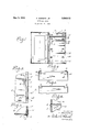
- Figure 1 of the drawings is a front elevational view of a wardrobe trunk embodying my invention, showing the trunk open.
- Figure 2 is a fragmentary front elevational view of the. drawer section of the trunk, illustrating one of the locking bars in its operative position.
- Figure 3 is a horizontal sectional view, taken on the line 3-3 of Figure 2'.
- Figure 4 is a bottom plan view of the master drawer.
- Figure 5 is a front elevational view of the drawer located directly underneath the master drawer.
- Figure 6 is a vertical sectional view, taken on the line 66 of Figure 2'.
- :0 designatesthe drawer section or drawer compartment of a wardrobe trunk, that is equipped with a plurality of drawers ari ranged in superimposedrelation.
- a drawer locking mechanism consisting of a key-controlled lock 1 associated with one drawer of the trunk, which I will refer'to as the master drawer A, and one or more looking members 2 associated with the remaining drawers B in such a way that the user can easily shift said locking member or looking members 2 into a position to co-act with the hey-controlled master drawer A.
- the key-controlled drawer preferably consists of the top drawer of the trunk, and two locking members 2 are preferablyprovided for the remaining drawers B, although this particular arrangement of elements is not essential to the successful operation of my invention.
- the locking members 2 are permanently mounted on the drawer section w of the trunk and are arranged at the front side of said drawer section so they will be easily accessible for installation and repair. As shown in the drawings, particularly Figure 3, the locking members 2 are pivotally mounted in such a way that they can be swung inwardly into overlapping relation with thedrawers B, or can be swung outwardly into the dotted line position shown in Figure 3, so as to not interfere with the opening and closing of the v drawers B.
- the key-controlled drawer or master drawer A co-acts with the locking members 2 to prevent saidmembers from shifting, or moving into an inoperative position to release the drawers B, but when the locking members 2 are arranged in their inoperative position, as shown in broken lines in Figure 3, the drawers B can be opened or closed at the will of the user, even though the master drawer A is locked.”
- This is a very desirable characteristic of a wardrobe trunk, as it permits the user or owner of the trunk to keep one drawer in the locked condition, when the trunk is open, and still have access to the other drawers, without resorting to the use of a keyeach time it is desired to open one of the drawersB.
- each of the locking members 2 consists of a flat metal bar arranged vertically at the front edge of one of the side walls :10 of the drawer section of the trunk and permanently mounted on same by means of a plurality of hinges 3, one leaf of each of said hinges being permanently riveted or otherwise connected to the locking member 2, and the other leaf of the hinge being set in a recess in the side wall as under the valance iron :20", which is usually attached to the side wall of the drawer section at the front edge of same, as shown clearly in Figure 3.
- each member 2 is bent inwardly or offset slightly, as shown in Figure 2, and the master drawer A has attached to the front edge of the bottom of same a plurality of retaining devices 4;, which are of such construction that when the locking members are in their operative position and the master drawer A is closed, as shown in Figure 2, the retaining devices 4 on said master drawer will lap over the upper end portions of the locking members 2, and thus effectively prevent said locking members from being swung outwardly into a position to release the drawers B.
- the retaining devices 4 herein illustrated are of substantially channel shape in horizontal section and are provided with integral attaching plates 4 that are connected by rivets l or in any other suitable way, to the bottom of the master drawer A.
- the top edge of the front wall of said drawer B is provided with notches 5, as shown in Figure 5, that are arranged in alignment with the depending retaining devices l on the master drawer, said notches 5 being large enough so that the retaining devices 4 will clear the edges of said notches, if said notched drawer is pulled forwardly when the master drawer A is in its locked position.
- the user desires to .keep all of the drawers of the trunk in a locked condition when the trunk is open, the user moves the locking members 2 into their operative position in overlapping relationship with the drawers B, as shown in full lines in Figures 2 and 3, and then closes the master drawer A and looks it by manipulating the lock 1 on said master drawer. So long as the drawer A remains locked, it is impossible to open any one of the drawers B, due, of course, to the fact that the retaining devices 4 on the master drawer co-act with the locking members 2 to retain said locking members in their operative position.
- the locking members 2 are mounted at the front side of the drawer section of the trunk permits said members to be installed easily; it also overcomes the necessity of tearing the drawer section of the trunk apart in the event it becomes necessary to repair the drawer locking mechanism or replace any of the parts of same, and it overcomes the necessity of making the drawers small enoughto provide a clearance between the drawers and the vertical walls of the drawer section for the parts of the drawer locking mechanism, thereby enabling the full storage space or the carrying capacity of the drawers to be utilized; such a drawer looking mechanism is inexpensive to construct; it is easy to operate as the coacting parts of same are permanently mounted on the trunk,
- the locking members 2 are of sufficiently rugged design, and are mounted on the drawer section 2 of the trunk in such a way that they form a highly efiicient looking means for the drawers B when the trunk is open, and also eliminate the possibility of said drawers shifting or moving when the trunk is in transit.
- a wardrobe trunk having a drawer section equipped with a plurality of drawers arranged in superimposed relation, a keycontrolled lock for the top drawer, a locking means for the drawers beneath the top drawer, consisting of a rigid bar pivotally connected to the front edge of one side wall of the drawer section and adapted to be moved into overlapping relationship with the drawers it controls, the upper end portion of said locking bar being offset, and a retaining member on the top drawer that is adapted to co-act with the offset portion of said locking bar to hold said bar in its operative position.
- a wardrobe trunk having a drawer section equipped with a key-controlled master drawer and a plurality of other drawers arranged in superimposed relation, a shiftable locking member for said other drawers permanently mounted on said drawer section at the front edge of one of the side walls of same, a depending retaining device on the master drawer that is adapted to overlap the upper end portion of said locking member and hold it against movement, and a notch in the drawer located directly underneath the master drawer that provides a clearance for the retaining device on the master drawer.
- a wardrobe trunk having a drawer section provided with a plurality of drawers arranged in superimposed relation, a keycontrolled lock for the top drawer, locking members for the drawers beneath the top drawer connected by hinges to the front edge portions of the side walls of the drawer section and adapted to be moved into and out of overlapping relationship with the drawers which they control, and means on the top drawer that moves automatically into operative relationship with said locking members to hold them against movement when said top drawer is moved into its closed position and said locking members are in their looking position.
- a wardrobe trunk having a drawer section provided with a plurality of drawers arranged in superimposed relation, a keycontrolled lock for the top drawer, verti- Cally-disposed locking bars pivotally mounted on the side walls of the wardrobe section at the front edges of same and adapted to be moved into overlapping relationship with the drawers which they control, offset portions at the upper ends of said locking bars depending retaining devices on the top drawer that are adapted to overlap the offset upper end portions of said bars, and notches in the top edge of the front wall of the drawer located directly beneath the top drawer, arranged in alignment with said retainlng devices, for the purpose described.
Landscapes
- Drawers Of Furniture (AREA)
Description
y 3, 1932- F. HERKERT, JR 1,856,913
WARDROBE TRUNK Filed Oct. 31, 1929 5y WM Patented May 3, 1932 UNITED STATES PA'rE'r @FFICE,
WARDROBE 'rRUNK Application filed October 31, 1929. Serial No. 403,797.
This invention relates to wardrobe trunks, and has for one of its objects to provide a wardrobe trunk that is equipped with an efficient drawer locking mechanism, which permits the user or owner to look all of the drawers or only one particular drawer when the trunk is opened, and which is of such design that the parts of said locking mechanism'cannot become lost or misplaced.
i Another object is to provide a drawer looking mechanism for wardrobe trunks, that is inexpensive to construct, easy to install and repair and of such design that it does not cut down the carrying capacity or storage space of the drawers.
And still another object is to provide a drawer locking mechanism for wardrobe trunks that is of rugged construction, easy to operate and of such design that it absolutely eliminates the possibility of the drawers shifting or moving when the trunk is in transit.
Figure 1 of the drawings is a front elevational view of a wardrobe trunk embodying my invention, showing the trunk open.
Figure 2 is a fragmentary front elevational view of the. drawer section of the trunk, illustrating one of the locking bars in its operative position.
Figure 3 is a horizontal sectional view, taken on the line 3-3 of Figure 2'.
Figure 4 is a bottom plan view of the master drawer.
Figure 5 is a front elevational view of the drawer located directly underneath the master drawer; and
Figure 6 is a vertical sectional view, taken on the line 66 of Figure 2'.
In the accompanying drawings which illustrate the preferred form of my invention, :0 designatesthe drawer section or drawer compartment of a wardrobe trunk, that is equipped with a plurality of drawers ari ranged in superimposedrelation. In order that the user or owner may look all of the drawers, or may look only one drawer when the trunk is open, I have equipped the trunk with a drawer locking mechanism consisting of a key-controlled lock 1 associated with one drawer of the trunk, which I will refer'to as the master drawer A, and one or more looking members 2 associated with the remaining drawers B in such a way that the user can easily shift said locking member or looking members 2 into a position to co-act with the hey-controlled master drawer A. to securely look all of the drawers of the trunk, or can arrange said locking member or members 2 in such a position that they will not interfere with the opening and closing ofthe drawers B 0 when the drawer A is locked. The key-controlled drawer preferably consists of the top drawer of the trunk, and two locking members 2 are preferablyprovided for the remaining drawers B, although this particular arrangement of elements is not essential to the successful operation of my invention.
The locking members 2 are permanently mounted on the drawer section w of the trunk and are arranged at the front side of said drawer section so they will be easily accessible for installation and repair. As shown in the drawings, particularly Figure 3, the locking members 2 are pivotally mounted in such a way that they can be swung inwardly into overlapping relation with thedrawers B, or can be swung outwardly into the dotted line position shown in Figure 3, so as to not interfere with the opening and closing of the v drawers B. When the locking members 2 are in their operative position, or in overlapping relationship with the drawers B, as shown in full lines inFigure 3, the key-controlled drawer or master drawer A co-acts with the locking members 2 to prevent saidmembers from shifting, or moving into an inoperative position to release the drawers B, but when the locking members 2 are arranged in their inoperative position, as shown in broken lines in Figure 3, the drawers B can be opened or closed at the will of the user, even though the master drawer A is locked." This is a very desirable characteristic of a wardrobe trunk, as it permits the user or owner of the trunk to keep one drawer in the locked condition, when the trunk is open, and still have access to the other drawers, without resorting to the use of a keyeach time it is desired to open one of the drawersB.
It isimmateriah so far as my broad idea is 100 concerned, how the locking members 2 are mounted on the drawer section m of the trunk, so long as they are permanently mounted on said section at the front side of same and are capable of being arranged in one position to hold the drawers B against movement into their open position, and are capable of being moved into a different position, so as to not interfere with the opening and closing of said drawers B. It is also immaterial, so far as my broad idea is concerned, how the locking members 2 are designed to coact with the master drawer A, so long as said master drawer will serve as a means that effectively prevents an unauthorized person from moving the looking members 2 into their inactive or inoperative positionat a time when said locking members are arranged to secure or hold the drawers B in their closed position. In the form of my invention herein shown each of the locking members 2 consists of a flat metal bar arranged vertically at the front edge of one of the side walls :10 of the drawer section of the trunk and permanently mounted on same by means of a plurality of hinges 3, one leaf of each of said hinges being permanently riveted or otherwise connected to the locking member 2, and the other leaf of the hinge being set in a recess in the side wall as under the valance iron :20", which is usually attached to the side wall of the drawer section at the front edge of same, as shown clearly in Figure 3. The upper end portion of each member 2 is bent inwardly or offset slightly, as shown in Figure 2, and the master drawer A has attached to the front edge of the bottom of same a plurality of retaining devices 4;, which are of such construction that when the locking members are in their operative position and the master drawer A is closed, as shown in Figure 2, the retaining devices 4 on said master drawer will lap over the upper end portions of the locking members 2, and thus effectively prevent said locking members from being swung outwardly into a position to release the drawers B. The retaining devices 4 herein illustrated are of substantially channel shape in horizontal section and are provided with integral attaching plates 4 that are connected by rivets l or in any other suitable way, to the bottom of the master drawer A. In order that the drawer B located directly underneath the master drawer A may be opened or closed, without disturbing the master drawer, the top edge of the front wall of said drawer B is provided with notches 5, as shown in Figure 5, that are arranged in alignment with the depending retaining devices l on the master drawer, said notches 5 being large enough so that the retaining devices 4 will clear the edges of said notches, if said notched drawer is pulled forwardly when the master drawer A is in its locked position.
If the user desires to .keep all of the drawers of the trunk in a locked condition when the trunk is open, the user moves the locking members 2 into their operative position in overlapping relationship with the drawers B, as shown in full lines in Figures 2 and 3, and then closes the master drawer A and looks it by manipulating the lock 1 on said master drawer. So long as the drawer A remains locked, it is impossible to open any one of the drawers B, due, of course, to the fact that the retaining devices 4 on the master drawer co-act with the locking members 2 to retain said locking members in their operative position. To release any one of the drawers B it is necessary to first unlock and open the master drawer A, and then swing the locking members 2 outwardly into such a position that they do not overlap or interfere with the opening or closing of the drawers B. If the user desires to retain one drawer of the trunk in a locked condition and still be able to open and close the other drawers without the necessity of resorting to the use of a key each time one of said other drawers is opened and closed, the locking members 2 are arranged in their inoperative position, shown in broken lines in Figure 3, before the master drawer A is locked.
The fact that the locking members 2 are mounted at the front side of the drawer section of the trunk permits said members to be installed easily; it also overcomes the necessity of tearing the drawer section of the trunk apart in the event it becomes necessary to repair the drawer locking mechanism or replace any of the parts of same, and it overcomes the necessity of making the drawers small enoughto provide a clearance between the drawers and the vertical walls of the drawer section for the parts of the drawer locking mechanism, thereby enabling the full storage space or the carrying capacity of the drawers to be utilized; such a drawer looking mechanism is inexpensive to construct; it is easy to operate as the coacting parts of same are permanently mounted on the trunk,
and there is no liability of any of the parts of said locking mechanismbecoming lost or misplaced. The locking members 2 are of sufficiently rugged design, and are mounted on the drawer section 2 of the trunk in such a way that they form a highly efiicient looking means for the drawers B when the trunk is open, and also eliminate the possibility of said drawers shifting or moving when the trunk is in transit. The above-described desirable characteristics of my trunk, coupled with the fact that the user can look all of the drawers with a single key, or can keep the master drawer in a locked condition and still be able to open and close any of the drawers B without resorting to theuse of a key, makes my trunk a decided improvement on the various makes of wardrobe trunks now in general use.
Having thus described my invention, what I claim as new and desire to secure by Letters Patent is:
1. A wardrobe trunk having a drawer section equipped with a plurality of drawers arranged in superimposed relation, a keycontrolled lock for the top drawer, a locking means for the drawers beneath the top drawer, consisting of a rigid bar pivotally connected to the front edge of one side wall of the drawer section and adapted to be moved into overlapping relationship with the drawers it controls, the upper end portion of said locking bar being offset, and a retaining member on the top drawer that is adapted to co-act with the offset portion of said locking bar to hold said bar in its operative position.
2. A wardrobe trunk having a drawer section equipped with a key-controlled master drawer and a plurality of other drawers arranged in superimposed relation, a shiftable locking member for said other drawers permanently mounted on said drawer section at the front edge of one of the side walls of same, a depending retaining device on the master drawer that is adapted to overlap the upper end portion of said locking member and hold it against movement, and a notch in the drawer located directly underneath the master drawer that provides a clearance for the retaining device on the master drawer.
3. A wardrobe trunk having a drawer section provided with a plurality of drawers arranged in superimposed relation, a keycontrolled lock for the top drawer, locking members for the drawers beneath the top drawer connected by hinges to the front edge portions of the side walls of the drawer section and adapted to be moved into and out of overlapping relationship with the drawers which they control, and means on the top drawer that moves automatically into operative relationship with said locking members to hold them against movement when said top drawer is moved into its closed position and said locking members are in their looking position.
4. A wardrobe trunk having a drawer section provided with a plurality of drawers arranged in superimposed relation, a keycontrolled lock for the top drawer, verti- Cally-disposed locking bars pivotally mounted on the side walls of the wardrobe section at the front edges of same and adapted to be moved into overlapping relationship with the drawers which they control, offset portions at the upper ends of said locking bars depending retaining devices on the top drawer that are adapted to overlap the offset upper end portions of said bars, and notches in the top edge of the front wall of the drawer located directly beneath the top drawer, arranged in alignment with said retainlng devices, for the purpose described.
FREDERICK HERKERT, J R.
Priority Applications (1)
| Application Number | Priority Date | Filing Date | Title |
|---|---|---|---|
| US403797A US1856913A (en) | 1929-10-31 | 1929-10-31 | Wardrobe trunk |
Applications Claiming Priority (1)
| Application Number | Priority Date | Filing Date | Title |
|---|---|---|---|
| US403797A US1856913A (en) | 1929-10-31 | 1929-10-31 | Wardrobe trunk |
Publications (1)
| Publication Number | Publication Date |
|---|---|
| US1856913A true US1856913A (en) | 1932-05-03 |
Family
ID=23597033
Family Applications (1)
| Application Number | Title | Priority Date | Filing Date |
|---|---|---|---|
| US403797A Expired - Lifetime US1856913A (en) | 1929-10-31 | 1929-10-31 | Wardrobe trunk |
Country Status (1)
| Country | Link |
|---|---|
| US (1) | US1856913A (en) |
Cited By (2)
| Publication number | Priority date | Publication date | Assignee | Title |
|---|---|---|---|---|
| US3902603A (en) * | 1974-07-01 | 1975-09-02 | Banner Metals | Retainer bar assembly for mail carrying rack |
| US20060022560A1 (en) * | 2004-07-28 | 2006-02-02 | Kevin Ashby | Filing cabinet with a locking system |
-
1929
- 1929-10-31 US US403797A patent/US1856913A/en not_active Expired - Lifetime
Cited By (2)
| Publication number | Priority date | Publication date | Assignee | Title |
|---|---|---|---|---|
| US3902603A (en) * | 1974-07-01 | 1975-09-02 | Banner Metals | Retainer bar assembly for mail carrying rack |
| US20060022560A1 (en) * | 2004-07-28 | 2006-02-02 | Kevin Ashby | Filing cabinet with a locking system |
Similar Documents
| Publication | Publication Date | Title |
|---|---|---|
| US3888558A (en) | Lock and interlock mechanism | |
| US2793927A (en) | Drawer locking mechanism | |
| US1436925A (en) | Lock for safety-deposit vaults and the like | |
| US1762477A (en) | Mail box | |
| US1856913A (en) | Wardrobe trunk | |
| US1955525A (en) | Group locker control | |
| US2163356A (en) | Delivery shutter | |
| US2130302A (en) | Cabinet door latch | |
| US1644215A (en) | Sectional-box mechanism | |
| US1613731A (en) | Wardrobe trunk | |
| US1607099A (en) | Locker | |
| US1366451A (en) | Latching device for trunk-drawers | |
| US1410995A (en) | Combination drawbolt and lock | |
| US1307253A (en) | Switch and coil-box lock | |
| US1702385A (en) | Assigrnob to dtjbabilt steel lockeb | |
| US1684513A (en) | Mail box | |
| US2728624A (en) | Cabinet structures | |
| US566135A (en) | Automatic lock-cabinet | |
| US495911A (en) | Combination-lock | |
| US2071732A (en) | Door latching mechanism | |
| US1966272A (en) | Lock | |
| KR200450284Y1 (en) | Double Lock Box | |
| US1387818A (en) | Safety-deposit appliance | |
| US1414162A (en) | Tray fastener for wardrobe trunks | |
| JP5682034B2 (en) | Locker lock |