US1856908A - Burial vault - Google Patents
Burial vault Download PDFInfo
- Publication number
- US1856908A US1856908A US440926A US44092630A US1856908A US 1856908 A US1856908 A US 1856908A US 440926 A US440926 A US 440926A US 44092630 A US44092630 A US 44092630A US 1856908 A US1856908 A US 1856908A
- Authority
- US
- United States
- Prior art keywords
- component
- vault
- lining
- lid
- bottom component
- Prior art date
- Legal status (The legal status is an assumption and is not a legal conclusion. Google has not performed a legal analysis and makes no representation as to the accuracy of the status listed.)
- Expired - Lifetime
Links
- 238000009933 burial Methods 0.000 title description 12
- 239000002184 metal Substances 0.000 description 11
- 229910052751 metal Inorganic materials 0.000 description 11
- 239000007767 bonding agent Substances 0.000 description 8
- 230000015572 biosynthetic process Effects 0.000 description 6
- 239000000463 material Substances 0.000 description 3
- 238000007789 sealing Methods 0.000 description 3
- 238000010276 construction Methods 0.000 description 2
- 230000035515 penetration Effects 0.000 description 2
- RYGMFSIKBFXOCR-UHFFFAOYSA-N Copper Chemical compound [Cu] RYGMFSIKBFXOCR-UHFFFAOYSA-N 0.000 description 1
- 208000024780 Urticaria Diseases 0.000 description 1
- 239000004568 cement Substances 0.000 description 1
- 229910052802 copper Inorganic materials 0.000 description 1
- 239000010949 copper Substances 0.000 description 1
- -1 for example Substances 0.000 description 1
- 239000007788 liquid Substances 0.000 description 1
- 238000000034 method Methods 0.000 description 1
- 230000008520 organization Effects 0.000 description 1
- 238000002360 preparation method Methods 0.000 description 1
- 239000007787 solid Substances 0.000 description 1
Images
Classifications
-
- E—FIXED CONSTRUCTIONS
- E04—BUILDING
- E04H—BUILDINGS OR LIKE STRUCTURES FOR PARTICULAR PURPOSES; SWIMMING OR SPLASH BATHS OR POOLS; MASTS; FENCING; TENTS OR CANOPIES, IN GENERAL
- E04H13/00—Monuments; Tombs; Burial vaults; Columbaria
Definitions
- This invention relates to vburial vaults, and has more particular reference to box-like burial vaults of concrete comprising bottom and lid components with linings of sheet metal.
- rlhe main objects of my invention are to insure, in connection with a. vault vof the specific type referred to, perfect bonding as between the metallic linings and the concrete l0 of the bottom and lid components; and to predetermine, incident to placement of the lid component on the bottom component after lowering of the burial casket at the time of interment, hermetic sealing of the vault without necessitating the aid of special securing devices or of special tools.
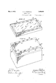
- FIG. 1 is a perspective view of the lid component in inverted position of my improved vault.
- Fig. Il is a similar view of the bottom component with the metallic lining thereof lifted partly out to better show the details of its construction.
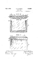
- Fig. III is a cross-sectional view of the lid component turned upside down.
- Fig. IV is a corresponding cross-sectional view of the bottom component.
- Fig. V is an end elevation of the vault with the lid component in place on the bottom component, a corner of the organization having been broken away and shown in section to illustrate how a hermetical seal is formed between the two components in accordance with the present improvement.
- my novel burial vault comprises a main or bottom component 10 of rectangular boislilre conc figuration, and a lid component 11, both constructed from concrete or the like.
- the main or bottom component 10 of the vault is provided with an inner surfacing or, lining 12 of non-corroding sheet metal, for example, copper, said lining being preferably separately made in the form of an insert with soldered or welded corner joints.
- the lining 12 has a lateral flange 13 that extends over the top edge of the bottom component 10. It willrfurther be noted that marginal portions of the flange 5 13 are downturned, as at 14, to slightly over- 1930. Serial No. 440,926.
- the lid component 11 is of solid concrete construction, and has, in its under face, a continuous perimetric recession 16 formed jointly through marginally reducing the thickness, and by a band 17 of stout metal inset around Vits perimeter.
- the lid component 11 is provided with a lining 18 of non-corroding sheet metal which 'covers its entire under surface including the vrecess 16.
- the lining 18 is preferably preformed and secured by interposition of a bonding agent'19. It is important to 'note that the lining 18 is turned up at the edges into the form of a flange 20, which,'.
- the bottom component 10 is placed in the open grave in preparation to receive the burial casket, and the lid placed alongsidethe grave and its perimetrio recesslf is filled with a slow hardening cem- Ventitious plastic, as Vshown at 22 in Fig. IH. After lowering ⁇ of the ,casketl into the bottom component 10 incident to interment,
- vthe lid component 11- is placedfright side up, upon Said componentsection 10, as shown in Fig. V, wherefrom it will be seen that theV depression 16 of the lid 'component 11 engages over the top .edge ⁇ of the bottom'component 10.
- the plastic cement 22 is compressed and oozes out from the juncture both interiorly and exteriorly of the vault, with formation of sealing Welts all around, as indicated at 23, 24 in Fig. V.
- the burial vault of my invention has all the advantages inherent to concrete, as regards strength and permanency, combined with the hermetic tightness of the sheet metal; both the concrete and the Ymetal being effectively sealed along the plane of juncture between the lid and bottom components 11, 10 by the cementitious bonding material previously applied to the perimetric recess in said lid component.
- the described method of sealing moreover greatly facilitates interment and obviates undue prolon gation of the ceremony.
- a burial vault of masonry comprising a box-like bottom component With a lining of non-corroding sheet metal having a flange to extend over the top edge of the bottom component and secured by an interposed film of cementitious bonding material, said flange being perforated for penetration by the bonding agent with attendant formation of retaining keys; and a lid component having a perimetric recess in its under face adapted to be filled with a slow-hardening cementitious plastic and to engage over the top edge of the bottom component, With formation of a hermetical seal all around When the lid component is placed in position on the bottom component incident to interment, said lid component being also provided with a lining of non-corroding sheet metal having key openings along the bottom of the perimetric recesses aforementioned.
- a burial vault of masonry comprisinga box-like bottom component with a lining of non-corroding sheet metal having a flange to extend over the top edge of the bottom component and secured by an interposed film of cementitious bonding material, said flange being perforated for penetration bythe bonding agent With attendant formation of retaining keys; and a lid component With a perimetric recess in its under face adapted to be filled with a slow-hardening cementitious 'plastic and to engage'over the top edge of the bottom component, with formation of a hermetical seal all around when the lid component is placed in position on the bottom component incident to interment, said lid component being also provided' With a lining of non-corroding sheet metal having openings in the flange of the lining of the bottom component.
Landscapes
- Engineering & Computer Science (AREA)
- Architecture (AREA)
- Civil Engineering (AREA)
- Structural Engineering (AREA)
- Casings For Electric Apparatus (AREA)
Description
May 3, 1932. R. D. coGswELL 1,856,908
BURIAL VAULT I Filed April 2, 1950 \2 Sheets-Sheet l' immuun W1 TNESSES IN VEN T MM 3mm@ 00g azz,
ATTORNEYS.
Patented May 3, 1.932
RICHARD* D. COGSWELL, OF MILLBOURNE, PENNSYLVANIA BURIAL VAULT Application filed April 2,
This invention relates to vburial vaults, and has more particular reference to box-like burial vaults of concrete comprising bottom and lid components with linings of sheet metal.
rlhe main objects of my invention are to insure, in connection with a. vault vof the specific type referred to, perfect bonding as between the metallic linings and the concrete l0 of the bottom and lid components; and to predetermine, incident to placement of the lid component on the bottom component after lowering of the burial casket at the time of interment, hermetic sealing of the vault without necessitating the aid of special securing devices or of special tools.
Referring to the attached drawings, Fig. lf
is a perspective view of the lid component in inverted position of my improved vault.
Fig. Il is a similar view of the bottom component with the metallic lining thereof lifted partly out to better show the details of its construction.
Fig. III is a cross-sectional view of the lid component turned upside down.
Fig. IV is a corresponding cross-sectional view of the bottom component; and,
Fig. V is an end elevation of the vault with the lid component in place on the bottom component, a corner of the organization having been broken away and shown in section to illustrate how a hermetical seal is formed between the two components in accordance with the present improvement.
As delineated in these illustrations, my novel burial vault comprises a main or bottom component 10 of rectangular boislilre conc figuration, and a lid component 11, both constructed from concrete or the like. The main or bottom component 10 of the vault is provided with an inner surfacing or, lining 12 of non-corroding sheet metal, for example, copper, said lining being preferably separately made in the form of an insert with soldered or welded corner joints. As shown in Figs. II and IV, the lining 12 has a lateral flange 13 that extends over the top edge of the bottom component 10. It willrfurther be noted that marginal portions of the flange 5 13 are downturned, as at 14, to slightly over- 1930. Serial No. 440,926.
lap the outside wall surfaces of the bottom component 10, said flange being formed at intervals with openings 15. Before assembling, I apply to the insides and to the top edOes of the bottom component 10, a layer .i
of a bonding agent such as molten tar or pitch, and then insert the lining 12 under sufl'icient pressure to insure compacting ofV the bonding agent 12 into the form of a continuous homogeneous film. Attendant upon this operation it will be apparent that some of the bonding agent Will ooze up through the openings 15 inthe flange 13 of the linin v12, with resultant formation of keys which lelectively assist in the retainme'nt of said lining within the component 10.
The lid component 11 is of solid concrete construction, and has, in its under face, a continuous perimetric recession 16 formed jointly through marginally reducing the thickness, and by a band 17 of stout metal inset around Vits perimeter. Like the bottom component `10, the lid component 11 is provided with a lining 18 of non-corroding sheet metal which 'covers its entire under surface including the vrecess 16. Here again, the lining 18 is preferably preformed and secured by interposition of a bonding agent'19. It is important to 'note that the lining 18 is turned up at the edges into the form of a flange 20, which,'.
in practice, is soldered or welded fast to the metallic band 17;fand, in addition, said li -V ing is provided within the'rec'ess 16 with a series of key openings 21 to correspond with the openings 15 in the flange 13 of the lining 12 in the bottom component 10 of the vault.
Y In the use of the vault, the bottom component 10 is placed in the open grave in preparation to receive the burial casket, and the lid placed alongsidethe grave and its perimetrio recesslf is filled with a slow hardening cem- Ventitious plastic, as Vshown at 22 in Fig. IH. After lowering `of the ,casketl into the bottom component 10 incident to interment,
vthe lid component 11-is placedfright side up, upon Said componentsection 10, as shown in Fig. V, wherefrom it will be seen that theV depression 16 of the lid 'component 11 engages over the top .edge `of the bottom'component 10. 'Dueto the weight ofthe lid component- Gil 11, the plastic cement 22 is compressed and oozes out from the juncture both interiorly and exteriorly of the vault, with formation of sealing Welts all around, as indicated at 23, 24 in Fig. V.
From the foregoing it- Will be seen that through my invention it is possible to fasten the lid component 11 of the vault in absolute liquid and gas tight relation to the main or box componentl 10 of the vault Without the aid of special securing means or of special tools, so that the interred body is protected against extraneous influences over an Vindefinite period of time, the juncture being made positively eflicient through complete mergence of the various bonding agents 12, 19 employed in the structure by Way of the key openings 15, 21 in the metallic linings 12 and 18. In other Words, the burial vault of my invention has all the advantages inherent to concrete, as regards strength and permanency, combined with the hermetic tightness of the sheet metal; both the concrete and the Ymetal being effectively sealed along the plane of juncture between the lid and bottom components 11, 10 by the cementitious bonding material previously applied to the perimetric recess in said lid component. The described method of sealing moreover greatly facilitates interment and obviates undue prolon gation of the ceremony.
Having thus described my invention, I claim:
1. A burial vault of masonry comprising a box-like bottom component With a lining of non-corroding sheet metal having a flange to extend over the top edge of the bottom component and secured by an interposed film of cementitious bonding material, said flange being perforated for penetration by the bonding agent with attendant formation of retaining keys; and a lid component having a perimetric recess in its under face adapted to be filled with a slow-hardening cementitious plastic and to engage over the top edge of the bottom component, With formation of a hermetical seal all around When the lid component is placed in position on the bottom component incident to interment, said lid component being also provided with a lining of non-corroding sheet metal having key openings along the bottom of the perimetric recesses aforementioned.
2. A burial vault of masonry comprisinga box-like bottom component with a lining of non-corroding sheet metal having a flange to extend over the top edge of the bottom component and secured by an interposed film of cementitious bonding material, said flange being perforated for penetration bythe bonding agent With attendant formation of retaining keys; and a lid component With a perimetric recess in its under face adapted to be filled with a slow-hardening cementitious 'plastic and to engage'over the top edge of the bottom component, with formation of a hermetical seal all around when the lid component is placed in position on the bottom component incident to interment, said lid component being also provided' With a lining of non-corroding sheet metal having openings in the flange of the lining of the bottom component.
3. In a burial vault the combination of a box-like bottom component With a lining of non-corroding sheet 'metal lapping the upper marginal edge, a similarly sheathed cover having a perimetric recess in its underface to engage over said marginal edge, and openings in the engageable metal faces affording key Ways for reception of suitable bonding agent whereby the cover is effectively interlockingly sealed to the box-like component.
fl. In a burial vault the combination of a box-like bottom component with a lining ofv
Priority Applications (1)
| Application Number | Priority Date | Filing Date | Title |
|---|---|---|---|
| US440926A US1856908A (en) | 1930-04-02 | 1930-04-02 | Burial vault |
Applications Claiming Priority (1)
| Application Number | Priority Date | Filing Date | Title |
|---|---|---|---|
| US440926A US1856908A (en) | 1930-04-02 | 1930-04-02 | Burial vault |
Publications (1)
| Publication Number | Publication Date |
|---|---|
| US1856908A true US1856908A (en) | 1932-05-03 |
Family
ID=23750762
Family Applications (1)
| Application Number | Title | Priority Date | Filing Date |
|---|---|---|---|
| US440926A Expired - Lifetime US1856908A (en) | 1930-04-02 | 1930-04-02 | Burial vault |
Country Status (1)
| Country | Link |
|---|---|
| US (1) | US1856908A (en) |
-
1930
- 1930-04-02 US US440926A patent/US1856908A/en not_active Expired - Lifetime
Similar Documents
| Publication | Publication Date | Title |
|---|---|---|
| US3164880A (en) | Plastic casket | |
| US3596419A (en) | Waterproof concrete burial vault and method of construction | |
| US1856908A (en) | Burial vault | |
| US1985903A (en) | Burial vault | |
| US2188626A (en) | Burial vault | |
| US1878781A (en) | Burial vault | |
| US3273294A (en) | Burial vault with sectional inclined sidewalls | |
| US2265876A (en) | Burial vault | |
| US843314A (en) | Burial-vault. | |
| US1932792A (en) | Burial vault | |
| US1785156A (en) | Burial vault | |
| US2103547A (en) | Burial vault | |
| US642504A (en) | Grave-vault. | |
| US2192104A (en) | Burial vault with metal lining | |
| US2150778A (en) | Burial vault | |
| US2036816A (en) | Burial vault | |
| US1502217A (en) | Burial vault | |
| US2429000A (en) | Grave vault | |
| US1706671A (en) | Concrete grave box | |
| JPS604958Y2 (en) | Water-stop structure for underground storage tanks | |
| US1915025A (en) | Grave vault | |
| US1421967A (en) | Burial box | |
| US1043664A (en) | Casket or coffin. | |
| US1790314A (en) | Btjbiaz | |
| US2135559A (en) | Burial vault |