US1856902A - Apparatus for burning powdered fuel - Google Patents
Apparatus for burning powdered fuel Download PDFInfo
- Publication number
- US1856902A US1856902A US171098A US17109827A US1856902A US 1856902 A US1856902 A US 1856902A US 171098 A US171098 A US 171098A US 17109827 A US17109827 A US 17109827A US 1856902 A US1856902 A US 1856902A
- Authority
- US
- United States
- Prior art keywords
- air
- fuel
- deflectors
- conduit
- stream
- Prior art date
- Legal status (The legal status is an assumption and is not a legal conclusion. Google has not performed a legal analysis and makes no representation as to the accuracy of the status listed.)
- Expired - Lifetime
Links
Images
Classifications
-
- F—MECHANICAL ENGINEERING; LIGHTING; HEATING; WEAPONS; BLASTING
- F23—COMBUSTION APPARATUS; COMBUSTION PROCESSES
- F23C—METHODS OR APPARATUS FOR COMBUSTION USING FLUID FUEL OR SOLID FUEL SUSPENDED IN A CARRIER GAS OR AIR
- F23C99/00—Subject-matter not provided for in other groups of this subclass
-
- F—MECHANICAL ENGINEERING; LIGHTING; HEATING; WEAPONS; BLASTING
- F23—COMBUSTION APPARATUS; COMBUSTION PROCESSES
- F23C—METHODS OR APPARATUS FOR COMBUSTION USING FLUID FUEL OR SOLID FUEL SUSPENDED IN A CARRIER GAS OR AIR
- F23C2700/00—Special arrangements for combustion apparatus using fluent fuel
- F23C2700/06—Combustion apparatus using pulverized fuel
- F23C2700/063—Arrangements for igniting, flame-guiding, air supply in
Definitions
- This invention relates to apparatuses for of rectangular cross section of a miXer and feeding powdered fuel.
- apparatuses of forms outer conduit near one end of which this type a maximum of turbulence of the is provided a transversely flanged connection gases is desired in order to increase the rate 2 which is connected with a suitable feeder,
- the outer conduit 1 may be 18* suchgases might, unless so governed, be deof any suitable cross section and in this in liver-ed directly to the stack, or cause eXcesstance is of rectangular shape and adapted sive furnace temperatures and possible deto support a plurality of transversely spaced struction ofrefractories, etc.
- cylindrical members 3 the latter adapted to .It is accordinglyan object of'thisinvention receive air under pressure and having their 15 to provide an apparatus of the above type in intake ends secured in transversely spaced which amaximum of turbulence of the gases apertures 4 respectively of a rectangular is obtained, the directions of the velocities plate 5.
- the plate 5 is secured to the intake present in the gases being so governed that end of the shell 1 adjacent the.
- connection 2 by they do not cause unburned gases to be .delivmeans of flanges 6 and 7 the latter on a sec- .ered to the stack even though the degree tion 8 of rectangular cross-section communiof such velocities is much higher than has eating with said end.
- bers 3 are adapted to receive therearound fuel More specifically it is an object of this infrom the opening within the connection 2 and .vention to provide an apparatus of the above each is provided at its discharge end with a type in which whirls and eddies of extreme set of cylindrically shaped deflector members velocities are created in the gases.
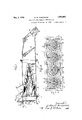
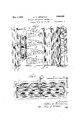
- FIG. 1 represents a longitudinalsectional its discharge endflared to cause the air to view of an, apparatus embodying this invencommingle with the stream of air and fuel tion. which is created around said members, as will Fig. 2is a plan view of the apparatus. be explained hereinafter, and is supported Fig. 3 is an end view of the apparatus, and in proper relation with respect to the other Fig. 4 is.
- numeral 1 represents a cylindrical shell of the members 3 acts to support the intake supports the intake ends of .thezcylinders 3 spending member .3 by supporting rods 1'5, .5
- more particuable stay 16 one in the'discharge end of each end of the corresponding deflector member 9 and another stay 17 in the discharge end of the shell 1 acts to support the discharge end of the series of deflector members.
- the discharge end of the shell 1 is provided with an annular flange 19 which is connected by a similar flange to a suitable nozzle 20 communicating with a furnace 21 or the like desired to receive the mixture adapted to be discharged from the shell as it leaves the said nozzle.
- the nozzle 20 is preferably provided with a closure 22 for shutting off communication between the shell 1 and the furnace 21 when desired.
- the section 8 contains the shutters for controlling the air supply to the shell 1 and is provided at the end therof opposite the flange 7 with a flange 23 which is adapted to be connected to a source of air supply. WVithin the section 8 there is pivotally mounted a plurality of "ertically spaced transversely extending shutters 24:, each of which is connected to an operating lever 25. Each of the levers 25 is pivotally connected at its outer end to a bar 26, the latter being pivotally connected at its upper end to the lower end of a rod 27 which is vertically slidable in a bearing 28 mounted in the upper side of the section 8. The upper end of the rod 27 is connected to the outer end of a lever 29 which is rigidly secured on a transversely extending rod 30.
- the rod 30 is mounted in suitable supports 31 on the section 8 and is provided with a hand lever 32 manually operable for closing or opening the shutters 24 to control the communication between the source of air supply and the intake end of the shell 1.
- the fuel in the form of powdered coal or a mixture thereof with air is admitted through the connection 2, such fuel falling by gravity around the cylinders 3 and being blown toward the discharge end of the shell 1 through means of the air coming from the source of air supply through a plurality of apertures 33 formed in the plate 5 around the apertures 4 therein.
- the shell 1 being of substantially uniform cross section from the intake to the discharge end thereof and the deflectors being of excessively decreasing size toward said discharge end, the column of air carrying the fuel which has been admitted through the connection 2 will be considerably rarefied toward said discharge end causing the fuel to be mixed with said air.
- the air entering the apertures 4 and the cylinders 3 will be given a maximum of turbulence through means of the deflectors by reason of the flared portions thereon.
- the flared portions on the deflectors will direct the air outwardly so as to cause it to commingle with the rarefied column of air and fuel around said deflectors.
- the deflectors being of successively diminishing size the pressure of the air coming through the cylinder 3 will not materially decrease throughout the successive deflectors.
- the character of the turbulence of the mixture will be such that the pressure of the air can be very great without danger of obtain-- ing too great a velocity in any given direction.
- means for feeding powdered fuel to a furnace means for supplying powdered fuel and air to the furnace, means for creating turbulence in the powdered fuel and air including a series of axially aligned annular outward deflectors disposed in the line of flow, said deflectors being of successively decreasing diameters in the direction of said flow.
- means for feeding powdered fuel to a furnace means for supplying powdered fuel and air to the furnace, means for creating turbulence in the powdered fuel and air including a series of axially aligned annular outward deflectors disposed in the line of flow, said deflectors being of successively decreasing diameters in the direction of said flow, the successive deflectors each having the intake thereof extending into the discharge end of the preceding deflector.
- means for feeding powdered fuel to a furnace means for supplying powdered fuel and air to the furnace, means for creating turbulence in the powdered fuel and air including a series of annular deflectors disposed in the line of flow, said deflectors being of successively decreasing diameters in the direction of said flow and having the discharge ends thereof flared outwardly.
- means for creating a turbulent stream of combustible mixture including a series of annular outward deflectors disposed in the line of flow, said deflectors being of successively decreasing size in the direction of said flow, and means for admitting a stream of air and fuel around said deflectors.
- means for creating a turbulent stream of combustible mixture including a series of out ward deflectors disposed in the line of flow,
- said deflectors being of successively decreasing size in the direction of said flow, a conduit surrounding said deflectors, and means for discharging a stream of air and fuel around said deflectors within said conduit.
- 'means for creating a turbulent stream of combustible mixture including a conduit having communicating with the interior thereof a series of outward deflectors of successively decreasing size in the direction of flow throughsaid conduit, an outer conduit surrounding said first conduit and deflectors, and means fordischargi-ng a stream of air and fuel around said first conduit and deflectors within said outer conduit.
- means for creating a turbulent stream of combustible mixturev including a series of outward deflectors disposed in the line of flow, said deflectors being of successively decreasing size in the direction of said flow, a conduit surrounding said deflectors, and means for discharging a stream of air and fuel around said deflectors within said conduit, said conduit having an effective cross sectional area outside of said deflectors of increasing size toward its discharge end utilized for conducting the mixture of air and fuel.
- means for creating a turbulent stream of combustible mixture including a conduit having communicating with the interior thereof aseries of outward deflectors of successively decreasing size in the direction of flow through said conduit, an outer conduit surrounding said first conduit and deflectors, and means for discharging a stream of air and fuel around said first conduit and deflectors within said outer conduit, said outer conduit having an effective cross sectional area outside of said deflectors of increasing size toward its discharge end utilized for conducting mix-ed air and fuel.
- a series of outwardideflectors of successively decreasing size from the intake to the discharge end a conduit surrounding said deflectors, means for admitting fuel to said conduit, and means for discharging air through said deflectors and through said conduit around the said deflectors.
- a conduit and aligned therewith a series of spaced apart outward deflectors of successively decreasing size in the direction of flow through said conduit, an outer conduit surrounding said first conduit and deflectors, means for admitting fuel to said outer conduit outside of said first conduit. and means for discharging air through said first conduit and the spacedgapart deflectors and through said outer conduit outside of said first conduit.
- a conduit and aligned therewith a series of spaced apart outward deflectors of successively decreasing size in the direction of flow tirough said conduit, an outer conduit surrounding said first conduit and deflectors, means for admitting fuel to said outer conduit outside of said first conduit, and means for admitting air through said first conduit and deflectors and through said outer conduit outside of said first-conduit, said last means including a plate secured to theintake end :of .said outer conduit, said plate having an aperture communicating with the intake end of said first conduit and a plurality of apertures surrounding said firstaperture and communicating with the interior of said outer conduit outside of said first conduit.
- means for feeding powdered fuel to a furnace means forsupplying powdered fuel and air to tl e furnace, means for creating turbulence in the powdered fuel and air including a series of spaced apart outward deflectors, disposed in the line of flow, said deflectors having successively decreasing cross sectional areas in the direction of said flow.
- means for feeding powdered fuel to a furnace means for supplying powdered fuel and air to the furnace, means for creating turbulence in the powdered fuel and-air including a series of spacedapart outward deflectors disposed in the line of flow, said deflectors having successively decreasing cross sectional areas in the direction of said flow, the successive deflectors each having the intake thereof extending into the discharge end of the preceding deflector.
- a device for feeding powdered fuel to a furnace means forsupplying powdered fuel and air to the furnace, means for creating turbulence in the powdered fuel and air including a series of axially aligned annular deflectors disposed in the line of flow, said deflectors being of successively decreasing diameters in the direction of said flow and having the discharge ends thereof flared outwardly.
- means for creating turbulence in the powdered fuel and air including a series of spaced apart deflectors disposed in the line of flow, said deflectors aving successively decreasing cross sectional areas in the direction of said flow, the successive deflectors each having the intake thereof extending into the discharge end of the preceding deflector, said deflectors having the discharge ends thereof flared outwardly.
- a device for feeding powdered fuel to .a furnace means for supplying powdered fuel and air to the furnace, means for creating turbulence in the powdered fuel and air ineluding a series of tubular deflectors disposed in the line of flow, said deflectors having successively decreasing cross sectional areas in the direction of said flow, the successive deflectors each having the intake thereof eX- tendinginto the discharge end of the preceding deflector, said deflectors having the discharge ends thereof flared outwardly.
- a device for feeding powdered fuel to. a furnace means for supplying powder-ed means for supplying powdered fuel and air to the furnace, means for creating turbulence in the powdered fuel and air including a series of annular members disposed in the line of flow, said members being of successively decreasing diameters in the direction of said flow, each member provided with a flared portion at its delivery end, the successive members each having the intake thereof extending into the delivery end of the preceding member beyond the flared portion thereof.
- the method of feeding powdered fuel comprising admixing air with powdered fuel by deflecting in succession successively adjacent annular portions of a central stream of air outwardly into a surrounding stream of air containing powdered fuel.
- a conduit means for creating a hollow stream of fuel and air within the conduit and a central stream of air within the stream of fuel and air, and means within the conduit for deflecting at successively spaced intervals adjacent annular portions of the central stream of air outwardly into the surrounding stream of fuel and air.
- a conduit means for creating a hollow stream of fuel within the conduit and a central stream of air within the fuel, and means within the conduit including a series of longitudinally spaced outward deflectors for mixing the air with the fuel.
- a conduit means for creating a hollow stream of fuel within the conduit and a central stream of air within the fuel stream, and means within the conduit including a series of longitudinally spaced annular outward deflectors for mixing the air with the fuel.
- a conduit means for creating a hollow stream of fuel within the conduit and a central stream of air within the fuel, and means within the conduit including a series of longitudinally spaced annular outward deflectors of successively decreasing size for mixing the air with the fuel.
- a conduit means for creating a hollow stream of fuel within the conduit and a central stream of air within the fuel, and means within the conduit including a series of longitudinally spaced annular outward deflectors of successively decreasing size for mixing the air with the fuel, some of the successive deflectors each having the intake thereof extending into the delivery end of the preceding deflector an amount as great as its own diameter.
- means for creating turbulence in a mixture of the fuel and air including a series of spaced apart tubular outward deflectors disposed in the line of flow of air, said deflectors having successively decreasing cross sectional areas in the direction of said flow.
- means for creatmg turbulence in the fuel mixture including a conduit and spaced apart outwardly flared tubular deflectors disposed in the line of flow of the air, means for admitting a flow of air into said conduit through said deflectors, means for admitting powdeied fuel to said conduit at a position where deflected air currents will carry it into suspension in the air, several of said deflectors having different cross sectional areas adapted to deflect and impart eddying motion to various portions of he air stream at different distances from its center line of flow.
- a method of creating and feeding a uniform turbulent mixture of fuel and air comprising forming a stream of air, forming the outermost layer of said air stream into an eddying body of moving air, adding the fuel to said eddying body, forming additional bodies of eddying air from said air stream and bringing these additional bodies successively into contact with the fuel mixture produced by said first body, and conducting the whole eddying mixture of fuel and air to a place for combustion.
- a method of making and feeding a turbulent uniform mixture of fuel and air comprising forming an annular body of swiftly eddying air currents, adding fuel to said body and mixing it therewith, forming additional concentric coaxial annular bodies of swiftly eddying air currents and projecting them into contact with said first body and with each other in fuel mixing relation adapted to provide a total uniform mixture of fuel and air, and feeding said mixture While in substantially uniform turbulent condition to a place of combustion.
- a method of making and feeding a uniform turbulent fuel mixture comprising forming an initial outer annular body of mixed fuel and air, forming within said body a series of additional inner annular bodies of air caused to move in swiftly eddying currents, and projecting said bodies in outward directions, and causing an ultimate uniform mixture by contacting said first body with the adjacent inner body so formed and each additional inner body with its respectively adjacent bodies.
Landscapes
- Engineering & Computer Science (AREA)
- Chemical & Material Sciences (AREA)
- Combustion & Propulsion (AREA)
- Mechanical Engineering (AREA)
- General Engineering & Computer Science (AREA)
Description
May 3, 1932. M. w. ARROWOOD 1,356,902
APPARATUS FOR BURNING POWDERED FUEL Original Filed Feb. 26; 1927 2 Sheets-Sheet 1 x 7iw em%rx Q MaZZZm Mrrawmd;
y 3, 1932- M. w. ARROWOOD APPARATUS FOR BURNING POWDERED FUEL Original Filed Feb. 26. 1927 2 Sheets-Sheet 2 Patented May 3, 1932 i UNETED STATES PATENT GFFEE MILTON W. ARROWOOD, OF GREENWIOH, CONNECTICUT APPARATUS FOR BURNING POWDERED. FUEL Application filed February-26, 1927, :Serial No. 171,098. Renewed March 18, 1932.
This invention relates to apparatuses for of rectangular cross section of a miXer and feeding powdered fuel. In apparatuses of forms outer conduit near one end of which this type a maximum of turbulence of the is provided a transversely flanged connection gases is desired in order to increase the rate 2 which is connected with a suitable feeder,
5 of heat transference by breaking down resistfor example, such as shown in connection .anceof gas films, etc. However, the amount with my copending application for United of turbulence that can be had in a furnace is States Letters Patent for apparatus for feed- .ordinarily limited unless the direction of the ing powdered fuel, Serial No. 624,927, filed velocities of thegases is properly governed, as March 14, 1923. The outer conduit 1 may be 18* suchgases might, unless so governed, be deof any suitable cross section and in this in liver-ed directly to the stack, or cause eXcesstance is of rectangular shape and adapted sive furnace temperatures and possible deto support a plurality of transversely spaced struction ofrefractories, etc. cylindrical members 3, the latter adapted to .It is accordinglyan object of'thisinvention receive air under pressure and having their 15 to provide an apparatus of the above type in intake ends secured in transversely spaced which amaximum of turbulence of the gases apertures 4 respectively of a rectangular is obtained, the directions of the velocities plate 5. The plate 5 is secured to the intake present in the gases being so governed that end of the shell 1 adjacent the. connection 2 by they do not cause unburned gases to be .delivmeans of flanges 6 and 7 the latter on a sec- .ered to the stack even though the degree tion 8 of rectangular cross-section communiof such velocities is much higher than has eating with said end. The cylindrical memheretofore been used. bers 3 are adapted to receive therearound fuel More specifically it is an object of this infrom the opening within the connection 2 and .vention to provide an apparatus of the above each is provided at its discharge end with a type in which whirls and eddies of extreme set of cylindrically shaped deflector members velocities are created in the gases. 9 to 14: inclusive adapted to outwardly de- It is further an object of this-invention to flect the air discharged from the member 3 provide an efilcient mixer of the air and fuel to create a maximum of turbulation in the to which thecoal, if desired, maybe delivered stream of air thus discharged. The memdirectly without necessitating such coal bebers 9 to 14 inclusive of each set are coaxial ing broken up by a stream of air preliminary with their respective member 3, are longitudito its admission to said mixer. nally spaced and of successively decreasing Other and further objects of this invention diameters from the discharge end of said will be apparent as the same becomes better member 3 forwardly toward the discharge understood from an examination of the speciend of the shell 1. The successive deflector fica-tion and claims when tal en in conjuncmembers have the intake of each thereof extion with the accompanying drawings, tending into the discharge end of'the precedwjherein ing one. Each of the deflector members has 'Fig. 1 represents a longitudinalsectional its discharge endflared to cause the air to view of an, apparatus embodying this invencommingle with the stream of air and fuel tion. which is created around said members, as will Fig. 2is a plan view of the apparatus. be explained hereinafter, and is supported Fig. 3 is an end view of the apparatus, and in proper relation with respect to the other Fig. 4 is. adetai-l view of the .plate which deflector members of the series and the correand communicates between the air supply, which extend from the discharge end of the the interiors of said cylinders. and they excorresponding cylindrical member 3 and are teriors thereof. attached to the deflector members. A suitlarly, numeral 1 represents a cylindrical shell of the members 3 acts to support the intake supports the intake ends of .thezcylinders 3 spending member .3 by supporting rods 1'5, .5
Referring to the drawings more particuable stay 16 one in the'discharge end of each end of the corresponding deflector member 9 and another stay 17 in the discharge end of the shell 1 acts to support the discharge end of the series of deflector members.
The discharge end of the shell 1 is provided with an annular flange 19 which is connected by a similar flange to a suitable nozzle 20 communicating with a furnace 21 or the like desired to receive the mixture adapted to be discharged from the shell as it leaves the said nozzle. The nozzle 20 is preferably provided with a closure 22 for shutting off communication between the shell 1 and the furnace 21 when desired.
The section 8 contains the shutters for controlling the air supply to the shell 1 and is provided at the end therof opposite the flange 7 with a flange 23 which is adapted to be connected to a source of air supply. WVithin the section 8 there is pivotally mounted a plurality of "ertically spaced transversely extending shutters 24:, each of which is connected to an operating lever 25. Each of the levers 25 is pivotally connected at its outer end to a bar 26, the latter being pivotally connected at its upper end to the lower end of a rod 27 which is vertically slidable in a bearing 28 mounted in the upper side of the section 8. The upper end of the rod 27 is connected to the outer end of a lever 29 which is rigidly secured on a transversely extending rod 30. The rod 30 is mounted in suitable supports 31 on the section 8 and is provided with a hand lever 32 manually operable for closing or opening the shutters 24 to control the communication between the source of air supply and the intake end of the shell 1.
In the operation of the apparatus the fuel in the form of powdered coal or a mixture thereof with air is admitted through the connection 2, such fuel falling by gravity around the cylinders 3 and being blown toward the discharge end of the shell 1 through means of the air coming from the source of air supply through a plurality of apertures 33 formed in the plate 5 around the apertures 4 therein. The shell 1 being of substantially uniform cross section from the intake to the discharge end thereof and the deflectors being of excessively decreasing size toward said discharge end, the column of air carrying the fuel which has been admitted through the connection 2 will be considerably rarefied toward said discharge end causing the fuel to be mixed with said air. Meanwhile the air entering the apertures 4 and the cylinders 3 will be given a maximum of turbulence through means of the deflectors by reason of the flared portions thereon. The flared portions on the deflectors will direct the air outwardly so as to cause it to commingle with the rarefied column of air and fuel around said deflectors. The deflectors being of successively diminishing size the pressure of the air coming through the cylinder 3 will not materially decrease throughout the successive deflectors.
The character of the turbulence of the mixture will be such that the pressure of the air can be very great without danger of obtain-- ing too great a velocity in any given direction.
I am aware that many changes may be made and many details varied throughout a wide range without departing from the principles of this invention and I do not therefore wish to be limited to the details shown and described.
I claim:
1, In a device for feeding powdered fuel to a furnace, means for supplying powdered fuel and air to the furnace, means for creating turbulence in the powdered fuel and air including a series of axially aligned annular outward deflectors disposed in the line of flow, said deflectors being of successively decreasing diameters in the direction of said flow.
2. In a device for feeding powdered fuel to a furnace, means for supplying powdered fuel and air to the furnace, means for creating turbulence in the powdered fuel and air including a series of axially aligned annular outward deflectors disposed in the line of flow, said deflectors being of successively decreasing diameters in the direction of said flow, the successive deflectors each having the intake thereof extending into the discharge end of the preceding deflector.
3. In a device for feeding powdered fuel to a furnace, means for supplying powdered fuel and air to the furnace, means for creating turbulence in the powdered fuel and air including a series of annular deflectors disposed in the line of flow, said deflectors being of successively decreasing diameters in the direction of said flow and having the discharge ends thereof flared outwardly.
4. In a device of the character described, means for creating a turbulent stream of combustible mixture including a series of annular outward deflectors disposed in the line of flow, said deflectors being of successively decreasing size in the direction of said flow, and means for admitting a stream of air and fuel around said deflectors. 1
5. In a device of the character described, means for creating a turbulent stream of combustible mixture including a series of out ward deflectors disposed in the line of flow,
said deflectors being of successively decreasing size in the direction of said flow, a conduit surrounding said deflectors, and means for discharging a stream of air and fuel around said deflectors within said conduit.
6'. In a device of the character described,
'means for creating a turbulent stream of combustible mixture including a conduit having communicating with the interior thereof a series of outward deflectors of successively decreasing size in the direction of flow throughsaid conduit, an outer conduit surrounding said first conduit and deflectors, and means fordischargi-ng a stream of air and fuel around said first conduit and deflectors within said outer conduit.
7. In a device of the character described,
means for creating a turbulent stream of combustible mixturev including a series of outward deflectors disposed in the line of flow, said deflectors being of successively decreasing size in the direction of said flow, a conduit surrounding said deflectors, and means for discharging a stream of air and fuel around said deflectors within said conduit, said conduit having an effective cross sectional area outside of said deflectors of increasing size toward its discharge end utilized for conducting the mixture of air and fuel.
8. In a deviceof the character described, means for creating a turbulent stream of combustible mixture including a conduit having communicating with the interior thereof aseries of outward deflectors of successively decreasing size in the direction of flow through said conduit, an outer conduit surrounding said first conduit and deflectors, and means for discharging a stream of air and fuel around said first conduit and deflectors within said outer conduit, said outer conduit having an effective cross sectional area outside of said deflectors of increasing size toward its discharge end utilized for conducting mix-ed air and fuel.
9. In a device of the character described, a series of outwardideflectors of successively decreasing size from the intake to the discharge end, a conduit surrounding said deflectors, means for admitting fuel to said conduit, and means for discharging air through said deflectors and through said conduit around the said deflectors.
10. In .a device of the character described, a conduit and aligned therewith a series of spaced apart outward deflectors of successively decreasing size in the direction of flow through said conduit, an outer conduit surrounding said first conduit and deflectors, means for admitting fuel to said outer conduit outside of said first conduit. and means for discharging air through said first conduit and the spacedgapart deflectors and through said outer conduit outside of said first conduit.
11. In a device of the character described, a conduit and aligned therewith a series of spaced apart outward deflectors of successively decreasing size in the direction of flow tirough said conduit, an outer conduit surrounding said first conduit and deflectors, means for admitting fuel to said outer conduit outside of said first conduit, and means for admitting air through said first conduit and deflectors and through said outer conduit outside of said first-conduit, said last means including a plate secured to theintake end :of .said outer conduit, said plate having an aperture communicating with the intake end of said first conduit and a plurality of apertures surrounding said firstaperture and communicating with the interior of said outer conduit outside of said first conduit.
12. In a device for feeding powdered fuel to a furnace, means forsupplying powdered fuel and air to tl e furnace, means for creating turbulence in the powdered fuel and air including a series of spaced apart outward deflectors, disposed in the line of flow, said deflectors having successively decreasing cross sectional areas in the direction of said flow.
13. In a device for feeding powdered fuel to a furnace, means for supplying powdered fuel and air to the furnace, means for creating turbulence in the powdered fuel and-air including a series of spacedapart outward deflectors disposed in the line of flow, said deflectors having successively decreasing cross sectional areas in the direction of said flow, the successive deflectors each having the intake thereof extending into the discharge end of the preceding deflector.
te In a device for feeding powdered fuel to a furnace, means forsupplying powdered fuel and air to the furnace, means for creating turbulence in the powdered fuel and air including a series of axially aligned annular deflectors disposed in the line of flow, said deflectors being of successively decreasing diameters in the direction of said flow and having the discharge ends thereof flared outwardly.
15. In a device for feeding powdered fuel to a furnace, fuel and air to the furnace, means for creating turbulence in the powdered fuel and air including a series of spaced apart deflectors disposed in the line of flow, said deflectors aving successively decreasing cross sectional areas in the direction of said flow, the successive deflectors each having the intake thereof extending into the discharge end of the preceding deflector, said deflectors having the discharge ends thereof flared outwardly.
16. In a device for feeding powdered fuel to .a furnace, means for supplying powdered fuel and air to the furnace, means for creating turbulence in the powdered fuel and air ineluding a series of tubular deflectors disposed in the line of flow, said deflectors having successively decreasing cross sectional areas in the direction of said flow, the successive deflectors each having the intake thereof eX- tendinginto the discharge end of the preceding deflector, said deflectors having the discharge ends thereof flared outwardly.
17. In a device for feeding powdered fuel to. a furnace,means for supplying powder-ed means for supplying powdered fuel and air to the furnace, means for creating turbulence in the powdered fuel and air including a series of annular members disposed in the line of flow, said members being of successively decreasing diameters in the direction of said flow, each member provided with a flared portion at its delivery end, the successive members each having the intake thereof extending into the delivery end of the preceding member beyond the flared portion thereof.
18. The method of feeding powdered fuel comprising admixing air with powdered fuel by deflecting in succession successively adjacent annular portions of a central stream of air outwardly into a surrounding stream of air containing powdered fuel.
19. In a device of the character described, a conduit, means for creating a hollow stream of fuel and air within the conduit and a central stream of air within the stream of fuel and air, and means within the conduit for deflecting at successively spaced intervals adjacent annular portions of the central stream of air outwardly into the surrounding stream of fuel and air.
20. In a device of the character described, a conduit, means for creating a hollow stream of fuel within the conduit and a central stream of air within the fuel, and means within the conduit including a series of longitudinally spaced outward deflectors for mixing the air with the fuel.
21. In a device of the character described, a conduit, means for creating a hollow stream of fuel within the conduit and a central stream of air within the fuel stream, and means within the conduit including a series of longitudinally spaced annular outward deflectors for mixing the air with the fuel.
22. In a device of the character described, a conduit, means for creating a hollow stream of fuel within the conduit and a central stream of air within the fuel, and means within the conduit including a series of longitudinally spaced annular outward deflectors of successively decreasing size for mixing the air with the fuel.
23. In a device of the character described, a conduit, means for creating a hollow stream of fuel within the conduit and a central stream of air within the fuel, and means within the conduit including a series of longitudinally spaced annular outward deflectors of successively decreasing size for mixing the air with the fuel, some of the successive deflectors each having the intake thereof extending into the delivery end of the preceding deflector an amount as great as its own diameter.
24. In a device for feeding powdered fuel to a furnace, means for creating turbulence in a mixture of the fuel and air including a series of spaced apart tubular outward deflectors disposed in the line of flow of air, said deflectors having successively decreasing cross sectional areas in the direction of said flow.
25. In a device for feeding powdered fuel mixed with air to a furnace, means for creatmg turbulence in the fuel mixture including a conduit and spaced apart outwardly flared tubular deflectors disposed in the line of flow of the air, means for admitting a flow of air into said conduit through said deflectors, means for admitting powdeied fuel to said conduit at a position where deflected air currents will carry it into suspension in the air, several of said deflectors having different cross sectional areas adapted to deflect and impart eddying motion to various portions of he air stream at different distances from its center line of flow.
26. A method of creating and feeding a uniform turbulent mixture of fuel and air comprising forming a stream of air, forming the outermost layer of said air stream into an eddying body of moving air, adding the fuel to said eddying body, forming additional bodies of eddying air from said air stream and bringing these additional bodies successively into contact with the fuel mixture produced by said first body, and conducting the whole eddying mixture of fuel and air to a place for combustion.
27. A method of making and feeding a turbulent uniform mixture of fuel and air comprising forming an annular body of swiftly eddying air currents, adding fuel to said body and mixing it therewith, forming additional concentric coaxial annular bodies of swiftly eddying air currents and projecting them into contact with said first body and with each other in fuel mixing relation adapted to provide a total uniform mixture of fuel and air, and feeding said mixture While in substantially uniform turbulent condition to a place of combustion.
28. A method of making and feeding a uniform turbulent fuel mixture comprising forming an initial outer annular body of mixed fuel and air, forming within said body a series of additional inner annular bodies of air caused to move in swiftly eddying currents, and projecting said bodies in outward directions, and causing an ultimate uniform mixture by contacting said first body with the adjacent inner body so formed and each additional inner body with its respectively adjacent bodies.
In witness of the foregoing I aflix my signature. I
MILTON W. ARROWO OD.
Priority Applications (1)
| Application Number | Priority Date | Filing Date | Title |
|---|---|---|---|
| US171098A US1856902A (en) | 1927-02-26 | 1927-02-26 | Apparatus for burning powdered fuel |
Applications Claiming Priority (1)
| Application Number | Priority Date | Filing Date | Title |
|---|---|---|---|
| US171098A US1856902A (en) | 1927-02-26 | 1927-02-26 | Apparatus for burning powdered fuel |
Publications (1)
| Publication Number | Publication Date |
|---|---|
| US1856902A true US1856902A (en) | 1932-05-03 |
Family
ID=22622517
Family Applications (1)
| Application Number | Title | Priority Date | Filing Date |
|---|---|---|---|
| US171098A Expired - Lifetime US1856902A (en) | 1927-02-26 | 1927-02-26 | Apparatus for burning powdered fuel |
Country Status (1)
| Country | Link |
|---|---|
| US (1) | US1856902A (en) |
Cited By (2)
| Publication number | Priority date | Publication date | Assignee | Title |
|---|---|---|---|---|
| US2483911A (en) * | 1945-09-11 | 1949-10-04 | Phillips Petroleum Co | Injector |
| US2510240A (en) * | 1946-03-28 | 1950-06-06 | Reubin E Mayo | Solid fuel stoker, including auxiliary air feed means |
-
1927
- 1927-02-26 US US171098A patent/US1856902A/en not_active Expired - Lifetime
Cited By (2)
| Publication number | Priority date | Publication date | Assignee | Title |
|---|---|---|---|---|
| US2483911A (en) * | 1945-09-11 | 1949-10-04 | Phillips Petroleum Co | Injector |
| US2510240A (en) * | 1946-03-28 | 1950-06-06 | Reubin E Mayo | Solid fuel stoker, including auxiliary air feed means |
Similar Documents
| Publication | Publication Date | Title |
|---|---|---|
| US1102510A (en) | Apparatus for burning finely-divided fuel. | |
| US2126417A (en) | Burner installation for boilers | |
| ES373703A1 (en) | Turbulence muffle burner | |
| US1856902A (en) | Apparatus for burning powdered fuel | |
| US1943286A (en) | Burner for furnaces | |
| US2684572A (en) | Segmental wall construction for combustion apparatus | |
| US2807316A (en) | Liquid fuel combustion chambers for jet-propulsion engines, gas turbines, or other purposes | |
| US989655A (en) | Spark and cinder extinguisher. | |
| US2229068A (en) | Burner | |
| US2474467A (en) | Heating apparatus | |
| US2660230A (en) | Oil burner | |
| US1878926A (en) | Pulverized fuel burner | |
| US2676649A (en) | Turbulator | |
| US1807977A (en) | Fuel burner | |
| US1677811A (en) | Gas burner | |
| US2754895A (en) | Single port gas burner and removable flame deflector | |
| US1678086A (en) | Gas burner | |
| US2119580A (en) | Fuel burner | |
| US1849812A (en) | Ventilator | |
| US1993901A (en) | Pulverized fuel burner | |
| US2765028A (en) | Air turbulence producing device | |
| US1882056A (en) | Distributor for gases carrying solids in suspension | |
| US2034932A (en) | Burner | |
| US1994447A (en) | Burner | |
| US814121A (en) | Gas-lamp. |