US1856901A - Oil burner - Google Patents
Oil burner Download PDFInfo
- Publication number
- US1856901A US1856901A US284295A US28429528A US1856901A US 1856901 A US1856901 A US 1856901A US 284295 A US284295 A US 284295A US 28429528 A US28429528 A US 28429528A US 1856901 A US1856901 A US 1856901A
- Authority
- US
- United States
- Prior art keywords
- burner
- segments
- fuel
- duct
- oil
- Prior art date
- Legal status (The legal status is an assumption and is not a legal conclusion. Google has not performed a legal analysis and makes no representation as to the accuracy of the status listed.)
- Expired - Lifetime
Links
Images
Classifications
-
- F—MECHANICAL ENGINEERING; LIGHTING; HEATING; WEAPONS; BLASTING
- F23—COMBUSTION APPARATUS; COMBUSTION PROCESSES
- F23D—BURNERS
- F23D11/00—Burners using a direct spraying action of liquid droplets or vaporised liquid into the combustion space
- F23D11/36—Details
- F23D11/40—Mixing tubes; Burner heads
Definitions
- the present invention relates to fuel burners and particularly to burners for use in connection with the combustion of liquid fuels.
- a further object of the present invention is to provide a liquid fuel burner arranged to effect vaporization and combustion of the fuel without deposition and accumulation of carbon deposits when operating with a relatively small excess of air.
- the invention consists in the improved liquid fuel burner hereinafter described and more particularly defined in the appended claims.
- Various features of the invention are illus- Serial No. 284,295.
- Fig. 1 is a vertical transverse sectional view with parts and elevations of a burner of the type constituting the preferred embodiment of the invention.
- Fig. 2 is a perspective view of the upper portion of the burner and vaporizingelement.
- Fig. 3 is a plan view of the vaporizing ele- V ment illustrated in Figs. 1 and 2, parts being broken away for the purpose of illustration.
- the apparatus herein illustrated includes an air duct 10 which extends vertically upward into a bowl 12 serving as a primary combustion chamber of the apparatus.
- Bowl 12 has a horizontal bottom 14: and preferably the duct 10 extends upwardly into the bowl forming a flange 16 to provide an annular channel or pocket 18 within the lower portion thereof, the purpose of channel 18 appearing hereinbelow.
- the vaporizing means for the oil or other liquid fuel is disposed immediately over the upper end of the duct 10 and in-
- Each blade 22 is a segment of a substantiallyhelical surface whose axis coincides with that of the vertical axis of the hub 20.
- the blades 22 are substantially quadrants of the circle whose center is at the center of the hub 20, the segments 22 being conveniently made similar to quadrants of a multi-threaded screw, being in this respect similar to the ordinary propeller type wind mill or propeller type fan.
- the segments 22 are warped from the helical so that their lower edges slant downwardly in passing outwardly from hub 20. Therefore, any oil which is not burned drips from the outer lower corners of the segments.
- the hub 20 and vanes 22 do not revolve, but
- Oil to be burned in the bowl 12 is brought up through apipe 2% which extends vertical- 1y through the center of the duct 10 and supports the hub 20 at its upper end.
- Hub 20 has an axial bore 26 therein communicating with the duct-throughpipe 2 i,'and hub 20 has radial slots 28, 28 in its upper edge leading outwardly from the bore 26 and adapted to deliver liquid from bore 26 to the upper surface of each of the segments 22. Oil delivered through slots 28, 28 to the upper surfaces of-the segments spreads out onthe segments 22 and flows toward the lower edges of the segments.
- Thelower portions of the outer circular edges of segments 22 and the lower radial edges of the segments are provided with upstanding vertical flanges 30 and 32 respectively formingshallow pockets or receptacles'33 so that, in case the oil is supplied to the segments 22 faster than it evaporates, small pools of liquid :fuel will be formed at the lower corners of the segments.
- the outer edges of segments 22 extend beyond the .flange 16 so that all the air passing up through the duct 10 will be given a whirling motion and also so that any excess fuel that maydrip off thelower corners of segments 22 when the burner is being started will fall into channel :18.
- the air may be forced into the duct 10 bymeans of a fan.
- the fan 34 delivers air to duct 10 by means of conduit 36.
- the useof a fan is in no wise essential to the invention.
- a pilot burner be em ployed in connection with the present invention, and a pilot burner 38 isillustrated, this being preferably placed close under oneof the segments 22, 22.
- Burner 38 may be conveniently supplied with gas through pipe 40 running through the duct 10 parallel to the oil pipe 24.
- pipe '39 is provided and arranged to drain off oil which may fall from the outer corners 31 of segments 22 into the annular space or channel 18.
- Pipe 39 delivers-into a drip pan or bucket 41.
- Bucket 41- is suspendedrby a bell crank 42 which is connectedtothe .-rot-atable member of cook 43 in such .amanner that when the bucket 431 is nearlyfull of oil the member 43 is turned, to cut off the flow of oil to the main burner through the oil pipe 14.
- a snap mechanism 46' holds the cook 43 normally open.
- the apparatus is able to burn oil with practicallyno carbon formation. and at the sametime veryv little excess air over that theoretically required for the combust-ion .of the oil. Itwill be obvious also that the apparatus according to the present invention is very simple and rugged, requiring no motor where the "natural draft is strong, since,'unless a fan is used, there are no rotating partsin the apparatus.
- a liquid fluid'burner having an air duct
- a liquid fluid burner having an air duct, a number of inclined spaced stationary fuel vaporizing plates arranged radially over the discharge end of said duct, and a conduit arranged to deliver liquid fuel to the upper surfaces of each of said plates, said duct terminating in a bowl partially enclosing and forming a combustion chamber for said burner.
- a burner for liquid fuel having an air conduit, a plurality of inclined spaced stationary fuel vaporizing plates arranged radially above a central hub over the upper end of said conduit, and a fuel pipe running from below said plates and connected to deliver oil to the upper surfaces of each of said plates.
- a fuel burner including an air conduit, a plurality of inclined spaced fuel vaporizing plates arranged over the upper end of said conduit, and a duct arranged and connected to deliver liquid fuel to the upper surfaces of each of said plates, said plates having flanges forming shallow pockets on the lower edges thereof.
- a burner for liquid fuel including a vertical air duct, a plurality of partially overlapping spaced inclined fuel vaporizing plates over the upper end of said duct, said plates extending outwardly beyond the edge of said duct, and a conduit arranged and connected to deliver liquid fuel to the upper surfaces of each of said plates.
- a burner for liquid fuel including a vertical air conduit, a series of inclined partially overlapping spaced fuel vaporizing plates arranged above the upper end of said conduit, a central hub to which said plates are connected, and a fuel duct running from below said plates through said hub, said hub having slots arranged to deliver fuel from said duct to the upper surfaces of said plates.
- a burner for liquid fuel including a vertical air conduit, a series of helically inclined spaced plates arranged above the upper end of said conduit, adjacent edges of adjoining plates lying one above the other, and a fuel duct arranged and connected to deliver liquid fuel to the upper surfaces of said plates.
- a burner for liquid fuel including a vertical air conduit, a bowl enclosing the upper end of said conduit and forming a pocket therewith, a plurality of helically inclined partially overlapping spaced fuel vaporizing plates arranged within said bowl above the upper end of said conduit and extending outwardly beyond the edge thereof to drain into said pocket, and a conduit arranged and connected to deliver liquid fuel to the upper surfaces of each of said plates.
- a burner apparatus for liquid fuel including a vertical air conduit, a bowl enclosing the .upper end of said conduit and forming a pocket therewith, a plurality of inclined spaced oil vaporizing plates arranged radially within the bowl above the upper end of said conduit and around a vertical hub, and means to feed liquid fuel through the hub to the upper surfaces of each of said plates, said plates having upwardly extend ing flanges along their lower radial edges to retain oil thereon and being arranged so that excess unburned oil will overflow into said pocket and so that air is caused toswirl upwardly thereover in intimate contact with the upper surfaces thereof.
- a liquid fuel burner comprising a combustion chamber, an air duct having a discharge outlet in said chamber, a combined stationary baffle and fuel vaporizing member mounted over said air duct discharge, said baffle member comprising a plurality of fuel vaporizing vanes arranged for swirling air into the combustion chamber in intimate contact with the fuel vaporizing surfaces thereof, and a conduit arranged and connected to deliver liquid fuel to the vaporizing surfaces of each of said vanes.
Landscapes
- Engineering & Computer Science (AREA)
- Chemical & Material Sciences (AREA)
- Combustion & Propulsion (AREA)
- Mechanical Engineering (AREA)
- General Engineering & Computer Science (AREA)
- Combustion Of Fluid Fuel (AREA)
Description
May 3, 1932. T. ANDERSON O I L BURNER Filed June 11. 1928 5110014 501 THOMAS ANDERSON Patented May 3, 1932 UNITE STATES FATE THOMAS ANDERSON, OF ELMHURST, NEW YORK, ASSIGNOR TO COMBUSTION UTILITIES CORPORATION, OF NEW YORK, N. Y., A CORPORATION OF MAINE OIL BURNER Application filed June 11, 1928.
The present invention relates to fuel burners and particularly to burners for use in connection with the combustion of liquid fuels.
A large number of types of burner apparatus have been placed on the market for burning oil or light fuel, but few of them have been able to operate satisfactorily under conditions where the fuel and draft varies considerably.
It is accordingly one of the objects of the present invention to provide a burner for liquid fuels which is simple in design, easy to install and operate, efiicient and reliable in operation.
A number of the burners now on the market designed for oil and like fuels are limited either to forced or to natural draft and are not adapted to use either one or the other as circumstances of different installations may 29 require.
It is the second object of the present invention to provide a burner for liquid fuel adapted to operate with either natural or forced draft air supply.
In a number of prior art designs of burners for liquid fuel the eflioiency has suffered because the apparatus has formed a nonuniform mixture of the oil vapor and air.
It is another object of the present invention to provide a burner for liquid fuel in which the fuel supplied is vaporized and the vapors are thoroughly and uniformly admixed with the air for combustion immenr diately before combustion takes place. Certain prior burners for liquid fuel have given trouble on account of forming carbon deposits which have accumulated in the apparatus.
A further object of the present invention is to provide a liquid fuel burner arranged to effect vaporization and combustion of the fuel without deposition and accumulation of carbon deposits when operating with a relatively small excess of air.
lVith these and other objects in view, the invention consists in the improved liquid fuel burner hereinafter described and more particularly defined in the appended claims. Various features of the invention are illus- Serial No. 284,295.
trated in the accompanying drawings, in which:
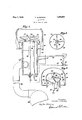
Fig. 1 is a vertical transverse sectional view with parts and elevations of a burner of the type constituting the preferred embodiment of the invention.
Fig. 2 is a perspective view of the upper portion of the burner and vaporizingelement.
Fig. 3 is a plan view of the vaporizing ele- V ment illustrated in Figs. 1 and 2, parts being broken away for the purpose of illustration.
Referring to the drawings more in detail, the apparatus herein illustrated includes an air duct 10 which extends vertically upward into a bowl 12 serving as a primary combustion chamber of the apparatus. Bowl 12 has a horizontal bottom 14: and preferably the duct 10 extends upwardly into the bowl forming a flange 16 to provide an annular channel or pocket 18 within the lower portion thereof, the purpose of channel 18 appearing hereinbelow. The vaporizing means for the oil or other liquid fuel is disposed immediately over the upper end of the duct 10 and in- Each blade 22 is a segment of a substantiallyhelical surface whose axis coincides with that of the vertical axis of the hub 20. In plan view, the blades 22 are substantially quadrants of the circle whose center is at the center of the hub 20, the segments 22 being conveniently made similar to quadrants of a multi-threaded screw, being in this respect similar to the ordinary propeller type wind mill or propeller type fan. As appears in F 1, the segments 22 are warped from the helical so that their lower edges slant downwardly in passing outwardly from hub 20. Therefore, any oil which is not burned drips from the outer lower corners of the segments.
The hub 20 and vanes 22 do not revolve, but
serve to give a swirling motion to the air which passes up into the bowl 12 through the duct 10, the vanes or segments 22 being spaced as illustrated to permit the air to pass between them.
Oil to be burned in the bowl 12 is brought up through apipe 2% which extends vertical- 1y through the center of the duct 10 and supports the hub 20 at its upper end. Hub 20 has an axial bore 26 therein communicating with the duct-throughpipe 2 i,'and hub 20 has radial slots 28, 28 in its upper edge leading outwardly from the bore 26 and adapted to deliver liquid from bore 26 to the upper surface of each of the segments 22. Oil delivered through slots 28, 28 to the upper surfaces of-the segments spreads out onthe segments 22 and flows toward the lower edges of the segments. Thelower portions of the outer circular edges of segments 22 and the lower radial edges of the segments are provided with upstanding vertical flanges 30 and 32 respectively formingshallow pockets or receptacles'33 so that, in case the oil is supplied to the segments 22 faster than it evaporates, small pools of liquid :fuel will be formed at the lower corners of the segments. The outer edges of segments 22 extend beyond the .flange 16 so that all the air passing up through the duct 10 will be given a whirling motion and also so that any excess fuel that maydrip off thelower corners of segments 22 when the burner is being started will fall into channel :18. It will=be seen that air which comes up through the duct '10 will be caused to whirl or rotate by the inclined segments 22 and, moreto come into more intimate contact with the oil on the upper faces of the segments 22. In order to produce a strong whirling action of the air at thetop of the duct 10, and also to increase the eddy and downward tendency of the air at the lower edges of the segments 22, the upper edge of the segments 22 are extended over thelower edges of adjacent segments to some extent as'clearly illustrated'inrFigs. 1 and 3.
If desired, the air may be forced into the duct 10 bymeans of a fan. 'In the arrangement illustrated, the fan 34 delivers air to duct 10 by means of conduit 36. The useof a fan, however, is in no wise essential to the invention.
It is preferred that a pilot burner be em ployed in connection with the present invention, and a pilot burner 38 isillustrated, this being preferably placed close under oneof the segments 22, 22. Burner 38 may be conveniently supplied with gas through pipe 40 running through the duct 10 parallel to the oil pipe 24.
lVhen it is desired to place the burner according to the present invention in use, oil is turned on so as to flow up through 'the pipe 24 and through slots 28 on to the segments 22. l/Vhen the fuel is first lighted the segments, of course, arerelatively cool and the 'VZtPOIIZHlZIOHlS at a-minlmum. Usually atthls period of the operation the oil is supplied somewhat faster than it burns and some of it collects in the pockets formed by the flanges 30-and 32. As segments 22 warm up,
pipe '39 is provided and arranged to drain off oil which may fall from the outer corners 31 of segments 22 into the annular space or channel 18. Pipe 39 delivers-into a drip pan or bucket 41. Bucket 41-is suspendedrby a bell crank 42 which is connectedtothe .-rot-atable member of cook 43 in such .amanner that when the bucket 431 is nearlyfull of oil the member 43 is turned, to cut off the flow of oil to the main burner through the oil pipe 14. A snap mechanism 46'holds the cook 43 normally open. According to the arrangement above described, the apparatus is able to burn oil with practicallyno carbon formation. and at the sametime veryv little excess air over that theoretically required for the combust-ion .of the oil. Itwill be obvious also that the apparatus according to the present invention is very simple and rugged, requiring no motor where the "natural draft is strong, since,'unless a fan is used, there are no rotating partsin the apparatus.
It will be understood that, while I have described above a specific apparatus, '1 do not limit myself to details of'th'erforegoing description-except insofar assuch details'are clearly and positively incorporated in the appended claims. In particular, it will =be understood-that the outline o-f'segments 22 in plan preferably depends upon the shape oft-he cross-section'of. duct-10, the outer edges of segments 22 being illustrated as circular in plan view in order to have the desired amount of overhang above pocketor channel 18 without waste of material in blades or segments 22.
Having thus described my invention 1 claim:
1. A liquid fluid'burnerhaving an air duct,
a number of inclined partially overlapping spaced fuel vaporizing plates arranged at one end of said duct, and a conduit arranged to deliver liquid fuel to the upper surfaces of each of said plates.
2. A liquid fluid burner having an air duct, a number of inclined spaced stationary fuel vaporizing plates arranged radially over the discharge end of said duct, and a conduit arranged to deliver liquid fuel to the upper surfaces of each of said plates, said duct terminating in a bowl partially enclosing and forming a combustion chamber for said burner.
3. A burner for liquid fuel having an air conduit, a plurality of inclined spaced stationary fuel vaporizing plates arranged radially above a central hub over the upper end of said conduit, and a fuel pipe running from below said plates and connected to deliver oil to the upper surfaces of each of said plates.
4. A fuel burner including an air conduit, a plurality of inclined spaced fuel vaporizing plates arranged over the upper end of said conduit, and a duct arranged and connected to deliver liquid fuel to the upper surfaces of each of said plates, said plates having flanges forming shallow pockets on the lower edges thereof.
5. A burner for liquid fuel including a vertical air duct, a plurality of partially overlapping spaced inclined fuel vaporizing plates over the upper end of said duct, said plates extending outwardly beyond the edge of said duct, and a conduit arranged and connected to deliver liquid fuel to the upper surfaces of each of said plates.
6. A burner for liquid fuel including a vertical air conduit, a series of inclined partially overlapping spaced fuel vaporizing plates arranged above the upper end of said conduit, a central hub to which said plates are connected, and a fuel duct running from below said plates through said hub, said hub having slots arranged to deliver fuel from said duct to the upper surfaces of said plates.
7. A burner for liquid fuel including a vertical air conduit, a series of helically inclined spaced plates arranged above the upper end of said conduit, adjacent edges of adjoining plates lying one above the other, and a fuel duct arranged and connected to deliver liquid fuel to the upper surfaces of said plates.
8. A burner as set forth in claim 6 and in which said plates have upstanding flanges forming shallow pockets thereon.
9. A burner for liquid fuel including a vertical air conduit, a bowl enclosing the upper end of said conduit and forming a pocket therewith, a plurality of helically inclined partially overlapping spaced fuel vaporizing plates arranged within said bowl above the upper end of said conduit and extending outwardly beyond the edge thereof to drain into said pocket, and a conduit arranged and connected to deliver liquid fuel to the upper surfaces of each of said plates.
10. A burner apparatus for liquid fuel including a vertical air conduit, a bowl enclosing the .upper end of said conduit and forming a pocket therewith, a plurality of inclined spaced oil vaporizing plates arranged radially within the bowl above the upper end of said conduit and around a vertical hub, and means to feed liquid fuel through the hub to the upper surfaces of each of said plates, said plates having upwardly extend ing flanges along their lower radial edges to retain oil thereon and being arranged so that excess unburned oil will overflow into said pocket and so that air is caused toswirl upwardly thereover in intimate contact with the upper surfaces thereof.
11. A liquid fuel burner comprising a combustion chamber, an air duct having a discharge outlet in said chamber, a combined stationary baffle and fuel vaporizing member mounted over said air duct discharge, said baffle member comprising a plurality of fuel vaporizing vanes arranged for swirling air into the combustion chamber in intimate contact with the fuel vaporizing surfaces thereof, and a conduit arranged and connected to deliver liquid fuel to the vaporizing surfaces of each of said vanes.
In testimony whereof I aflix my signature.
THOMAS ANDERSON.
Priority Applications (1)
| Application Number | Priority Date | Filing Date | Title |
|---|---|---|---|
| US284295A US1856901A (en) | 1928-06-11 | 1928-06-11 | Oil burner |
Applications Claiming Priority (1)
| Application Number | Priority Date | Filing Date | Title |
|---|---|---|---|
| US284295A US1856901A (en) | 1928-06-11 | 1928-06-11 | Oil burner |
Publications (1)
| Publication Number | Publication Date |
|---|---|
| US1856901A true US1856901A (en) | 1932-05-03 |
Family
ID=23089638
Family Applications (1)
| Application Number | Title | Priority Date | Filing Date |
|---|---|---|---|
| US284295A Expired - Lifetime US1856901A (en) | 1928-06-11 | 1928-06-11 | Oil burner |
Country Status (1)
| Country | Link |
|---|---|
| US (1) | US1856901A (en) |
Cited By (1)
| Publication number | Priority date | Publication date | Assignee | Title |
|---|---|---|---|---|
| US2470683A (en) * | 1944-09-15 | 1949-05-17 | Breese Burners Inc | Vertical semicylindrical burner |
-
1928
- 1928-06-11 US US284295A patent/US1856901A/en not_active Expired - Lifetime
Cited By (1)
| Publication number | Priority date | Publication date | Assignee | Title |
|---|---|---|---|---|
| US2470683A (en) * | 1944-09-15 | 1949-05-17 | Breese Burners Inc | Vertical semicylindrical burner |
Similar Documents
| Publication | Publication Date | Title |
|---|---|---|
| US2165162A (en) | Oil burning furnace | |
| US1856901A (en) | Oil burner | |
| US1695030A (en) | Rotary oil burner | |
| US1569967A (en) | Oil burner | |
| US2337088A (en) | Oil burning apparatus | |
| US2249878A (en) | Oil burner | |
| US2098455A (en) | Fluid fuel burner | |
| US1897318A (en) | Apparatus for burning liquid fuel | |
| US2275149A (en) | Oil burner | |
| US2228324A (en) | Hydrocarbon fuel burner | |
| US2179142A (en) | Hydrocarbon burner | |
| US1594520A (en) | Fuel-oil burner | |
| US2344439A (en) | Apparatus for burning liquid fuels | |
| US1886675A (en) | Oil burning furnace | |
| US2065264A (en) | Burner | |
| US1888476A (en) | Rotary oil burner | |
| US1593231A (en) | Liquid-fuel burner | |
| US2748847A (en) | Recirculating pilot and burner | |
| US1685567A (en) | Hydrocarbon oil burner | |
| US1293590A (en) | Crude-oil burner. | |
| US1631374A (en) | Oil burner | |
| US1639518A (en) | Burner | |
| US2468450A (en) | Perforated combustion tube oil burner | |
| US1410112A (en) | Island | |
| US1585221A (en) | Oil burner |