US1856884A - Means for the automatic weighing of goods of different kinds - Google Patents
Means for the automatic weighing of goods of different kinds Download PDFInfo
- Publication number
- US1856884A US1856884A US441627A US44162730A US1856884A US 1856884 A US1856884 A US 1856884A US 441627 A US441627 A US 441627A US 44162730 A US44162730 A US 44162730A US 1856884 A US1856884 A US 1856884A
- Authority
- US
- United States
- Prior art keywords
- belt
- goods
- weighing
- scale
- lever
- Prior art date
- Legal status (The legal status is an assumption and is not a legal conclusion. Google has not performed a legal analysis and makes no representation as to the accuracy of the status listed.)
- Expired - Lifetime
Links
Images

Classifications
-
- G—PHYSICS
- G01—MEASURING; TESTING
- G01G—WEIGHING
- G01G13/00—Weighing apparatus with automatic feed or discharge for weighing-out batches of material
-
- G—PHYSICS
- G01—MEASURING; TESTING
- G01G—WEIGHING
- G01G13/00—Weighing apparatus with automatic feed or discharge for weighing-out batches of material
- G01G13/003—Details; specially adapted accessories
-
- G—PHYSICS
- G01—MEASURING; TESTING
- G01G—WEIGHING
- G01G13/00—Weighing apparatus with automatic feed or discharge for weighing-out batches of material
- G01G13/02—Means for automatically loading weigh pans or other receptacles, e.g. disposable containers, under control of the weighing mechanism
-
- G—PHYSICS
- G01—MEASURING; TESTING
- G01G—WEIGHING
- G01G13/00—Weighing apparatus with automatic feed or discharge for weighing-out batches of material
- G01G13/24—Weighing mechanism control arrangements for automatic feed or discharge
- G01G13/242—Twin weighing apparatus; weighing apparatus using single load carrier and a plurality of weigh pans coupled alternately with the load carrier; weighing apparatus with two or more alternatively used weighing devices
-
- G—PHYSICS
- G01—MEASURING; TESTING
- G01G—WEIGHING
- G01G17/00—Apparatus for or methods of weighing material of special form or property
- G01G17/02—Apparatus for or methods of weighing material of special form or property for weighing material of filamentary or sheet form
-
- G—PHYSICS
- G01—MEASURING; TESTING
- G01G—WEIGHING
- G01G21/00—Details of weighing apparatus
Definitions
- his invention relates to a system of automatic weighing in which the material to be weighed is conveyed from a storage container to the weighing machine proper by means of 5 a continuously travelling endless belt, which is capable of altering periodically the direction of its travel so as to convey the material issuing from the storage container alternately into i'irst one and then the other of the two l@ scales with which the weighing machine is provided.
- the use of an endless band travelling alternately in two opposed directions enables the disadvantage of the hitherto known ⁇ devices for the conveyance of material into the scales of weighing machines to be avoided. namely the disadvantage that when goods such as tea, tobacco, or the like are being weighed the channels through which these goods flow on the way to the scales easily become blocked, because of the fibrous nature of the goods concerned.
- a conveying device incorporating ⁇ known types of drums is employed in connection with two scale beams, whereby the possibility is provided of weighing up portions with the required degree of accuracy.
- Figs. l and 2 illustrate diagrammatically the relative positions of the three elements A., B, and C-container, conveyor, and weighinfr machineconstitutmg the apparatus act5 cording to the invention.
- A is a storage and feed device for the uniw form delivery of material, for instance of tobacco, and is similar to that normally used in connection with cigarette making machines. rl ⁇ he tobacco is caught up by a continuously rotating spiked drum 2 and delivered to the outlet opening 3 (Figs. l and 2).
- the means usually employed are those indicated in the drawings, i. e.
- a spike drum i which removes superfluous tobacco from the spikes of the drum 2 and ensures a uniform 70 distribution of tobacco over the entire surface of the drum 2, an angulaior spike roller 5 which removes any tobacco adhering to the drum t and rejects it into the storage cham- N bei' i, and finally a roller G provided with needles which detachee the tobacco from the drum 2 and scatters the same on to a con ⁇ tinuously travelling' belt 7, which delivers the 'tobacco to the outlet opening 3.
- a belt 8 (see Fig'. l) disposed in the chamber 1 feeds 80 the material continuously to the roller 2, preventing the latter from running idle.
- a similar device can be used for the delivery of other goods, e. g. tea, or the like, from the storage chamber l, with the sole modiiication that the pick up drum 2 is pro-- vided with a suitable number of longitudinal grooves instead of the spikes employed in connection with the conveyance of tobacco.
- the conveyor proper -B-- consists of two pulley wheels 9 and 10 and an endless belt l1 (see Figs. 1 and 2).
- rlllie weighing machine -C- comprises a case containing ⁇ two balances 12a and 12?) provided with the scales 13a and 13b.
- the left-hand balance (in Fig. 2) is provided with contact springs 14a and 15a, and the right-hand balance with the contact springs 14o and 15b. The purpose of these springs will be hereinafter described.
- the beam 12a After the filling of the scale 13a the beam 12a is tilted and thus makes contact between the springs 14a and 15a, the belt 11 reverses its direction of travel and proceeds to convey the goods to the right-hand scale 135 again, and the scale 13a can then be emptied.
- the error in weight due to the after-flow of the amount contained in the column c-cZ can thus be accurately allowed for, and the claim of accuracy for the weighing in accordance with the described procees thus holds good, it being merely necessary te determine the speed of the delivery of the goods according to the size of the portions required, the absolute weight of th-e amount in the column c-rl being determined in advance and reckoned in with the total weight of the portion required.
- the described method of weighing is thus carried out with the help of two weighing machines, which alternately receive the goods to be weighed from a belt 11, which is itself uninterruptedly supplied from a delivery device A.
- the uninterrupted feed increases the working capacity of the apparatus and simplifies the construction of the same as compared with other known types of apparatus for the same purpose, which latter, as mentioned above, are under the disadvantage of having to be brought to a standstill at the conclusion of each separate weighing operation.
- the materials to be weighed out in portions are delivered by the apparatus A on to an endless belt 11, which is capable of being driven in either of two opposed directions by one of the two continuously and opposit-ely rotating drums 17a and 175, which are mounted on two shafts 18a and 185 connected together by means of the pinions 19a and 19?).
- These drums maybe driven from a main driving shaft 2O by means of pulley wheels 21 and 22 and a belt 23.
- a lever or pendulum is. mounted on a stud shaft 24 in such a manner as to be capable of oscillating, and is provided at its upper end with a cross piece forming two arms on which rollers 26a and 265 are mounted.
- the pen,- dulum 25 is designed to press the belt 11, by means of the rollers 26a and 265, against one or other of the pulley wheels 17a and 17?), and thus to cause the belt 11 to travel in one or the other of two opposed directions.
- the pulley wheels 17 a and 175 may be covered with an elastic material, e. g. rubber. for the purpose of ensuring adequate friction between the belt 11 and the pulley wheels 17a and 175.
- Fig. 3 the pendulum 25 is shown 4in a position in which it presses the belt 11 by means of the roller 26a against the pulley wheel 17a, so that the goods are conveyed into the scale pan 135.
- the emptying of the scale pans may be efe fected in any known manner (not shown in detail in the drawings), for instance by automatic tilting about an axis 33?), as indicated in Fig. 3.
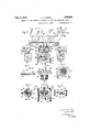
- the spring 32 is attached at one end to the pendulum lever rand at the other end to a crank lever 34 secured to a suitably mounted shaft 35, which also carries a jointed coupling, which is capable, under certain definite circumstances, of rotating the shaft 35 through 180.
- This coupling or clutch consists of the following parts (see Figs. 4 and 5) t--A cylindrical body 36, a link or eng'aging pin 37 with a latch 38, and a hollow cylindrical body 39 litting over the cylindrical body 36, which hollow cylindrical body is formed externally as a pulley and is provided internally with a continuous series of grooves 39a, 395, 390, etc. of semi-circular section and disposed parallel to the axis of the said hollow cylindrical body (see Fig. 4).
- This hollow cylinder 39 is continuously rotated by the main driving shaft 2O through the agency of a pulley 40 and a belt or cord 4l.
- the pendulum lever 25 is connected by means of rods 42 and 43 to cranked levers 44 and 45 (see Fig. 7), which are adapted to oscillate about shafts 46 and 47, which are mounted in suitable bearings.
- the purpose of the levers 44 and 45 is to control the jointed coupling or clutch by means of a hook 48 on the end of the lever 44 and a stop 49 on the end of the lever 45.
- the rod 42 holds the link or engaging pin 37, through the agency of the lever 44, the hook 48, and the latch 38, in a position which precludes the possibility of the engagement of the same with the hollow cylinder 39.
- thel pendulum lever 25 is released by the keeper 31a of the lever 30a as a result of the excitation of the electromagnet 27) and has been brought by the action of the spring 32 into the position shown in dotted lines in Fig.
- the hook 48 also comes out of engagement with the latch 38, with the result that the link 37 is actuated by the spring 50, engages in one of the grooves on the hollow cylinder 39 (Fig. 8), and thus causes the shaft 35 to be rotated.
- the rotation of the shaft 35 is however limited to 180 in extent, since the latch 38 comes up against the stop 49 on the lever 45, whereby the link 37 is simultaneously brought out of engagement with the hollow cylinder 39.
- the crank 34 Simultaneously with the rotation of the shaft 35 through half a revolution the crank 34 is rotated into a position opposed to that which it has hitherto occupied, so that the spring 32 is also reversed in position in regard to the pendulum lever 25 and is set to draw the latter from left to right, instead of from right to left as indicated in Fig. 3, at the end of the current filling phase.
- the link 37 rigidly connected with the latch 38 is of such form that when the latch is in the position shown in Fig. 4 the link is. completely depressed in the groove of the cylindrical body 36 so that no pa t of the link 37 projects beyond the periphery of the body 36.
- Secured to the latch 38 is one end of a spring 5() the other end of which is secured to the rear enlarged part of the body 36 (Fig. 5), whereby the spring will participate in the movement of the body 3G.
- thel latch 38 and link 37 will occupy the positions in relation to the cylindrical body 36 as shown in Fig. 8, provided that the outer end of the latch is not turned by any obstruction into the position shown in Fig. 4. In the position of Fig.
- a part of the latch 38 projects beyond the periphery of the cylindrical body 36 into one of the grooves 39a, 3922, etc., of the follow cylindrical body 39, and in this position of the parts the continuously driven body 39 will carry along with it the body 38 as these members are coupled together for rotation by thel link 37.
- rlhe size of the weighed portions in the scale pans 13a and 13?) depends upon the size of the weights 16a and 16h (see Fig. 2). It is therefore possible with the described apparatus, by the suitable proportioning of the weights 16a and 165, to weigh a different quantity in each of the two scale pans.
- Apparatus .for weighing materials comprising in combination with a device for the delivery of a uniform stream of the. material to be weighed, and in combination with two weighing machines of a normal and known type, an endless conveyor belt disposed beneL th the outlet of the said device for the delivery of a uniform stream of the material to be .reighed, two pulley wheels adapted to be rotated continuously in opposite directions, the said pulley wheels being adjacent the under surface of the idle portion of the said endless conveyor belt, and jockey rollers disposed adjacentl the upper surface of the idle portion of the said endless conveyor belt and means actuating said jockey rollers to press the said belt alternately against the one and the other of the said two opposedly rotating pulley wheels, for the purpose of conveying a continuous uniform stream of material alternatingly into the one and the other of the scale pans of t-he said t-wo weighing machines and of allowing time for the emptying of the one scale pan during the filling of the other, in
- Apparatus for weighing materials comprising in combination with a device for the delivery of a uniform stream of the material to be weighed, and in combination with two weighing machines of a normal and known type, an endless conveyor belt disposed beneath the outlet of the said device for the delivery of a uniform stream of the material to be weighed, two pulley wheels adapted to be rotated continuously in opposite directions, the said pulley wheels being adjacent the under surface of the idle portion of the said endless conveyor belt, jockey rollers disposed adjacent the upper surface of the idle portion of the said endless conveyor belt and adapted to press the said belt alternately against the one and the other of the said two opposedly rotating pulley wheels, a pendulum lever with a cross head piece to which the said jockey rollers'are attached, a pivot disposed at the head end of the said pendulum lever about which the same is adapted to oscillate, a spring attached to the said pendulum lever, and means adapted to alt-er the position of the said spring periodically from the one side of the said pendulum lever to the
- Apparatus for weighing materials comprising in combination with a device for the delivery of a uniform stream of the material to be weighed, and in combination with two weighing machines of a normal and known type ⁇ an endless conveyor belt disposed beneath the outlet of the said device for the delivery of a uniform' stream of the material to be weigh-ed, two pulley wheels adapted to be rotated continuously in opposite directions, the said pulley wheels being adjacent the under surface of the idle portion of the said endless conveyor belt, jockey rollers disposed adjacent the upper surface of the idle portion of the said endless conveyor belt and adapted to press the said belt alternately against the one and the other of the said two opposedly rotating pulley wheels, a pendulum lever with a cross'head piece to which the said jockey rollers are attached, a pivot disposed at the head end of the said pendulum lever about which the same is adapted to oscillate, a spring attached to the said pendulum lever, means adapted to alter the position of the said spring periodically from the one side of the said endulum lever to the
- Apparatus for weighing materials comprising an endless travelling belt adapted to discharge at opposite positions, weighing means adjacent each discharge position, and
- Apparatus for weighing materials com'- prising a pair of oppositely disposed rolls, an endless belt travelling thereover, weighing means adjacent each roll and adapted to receive material from the belt and means for alternately moving the belt in opposite directions to discharge material therefrom alternately into the several weighing means.
Landscapes
- Physics & Mathematics (AREA)
- General Physics & Mathematics (AREA)
- Weight Measurement For Supplying Or Discharging Of Specified Amounts Of Material (AREA)
- Manufacturing Of Cigar And Cigarette Tobacco (AREA)
- Filling Or Emptying Of Bunkers, Hoppers, And Tanks (AREA)
Applications Claiming Priority (1)
| Application Number | Priority Date | Filing Date | Title |
|---|---|---|---|
| CS43550X | 1929-04-05 |
Publications (1)
| Publication Number | Publication Date |
|---|---|
| US1856884A true US1856884A (en) | 1932-05-03 |
Family
ID=5386097
Family Applications (1)
| Application Number | Title | Priority Date | Filing Date |
|---|---|---|---|
| US441627A Expired - Lifetime US1856884A (en) | 1929-04-05 | 1930-04-04 | Means for the automatic weighing of goods of different kinds |
Country Status (6)
| Country | Link |
|---|---|
| US (1) | US1856884A (da) |
| AT (1) | AT128766B (da) |
| DE (1) | DE535800C (da) |
| DK (1) | DK43550C (da) |
| FR (1) | FR693119A (da) |
| GB (1) | GB339914A (da) |
Cited By (8)
| Publication number | Priority date | Publication date | Assignee | Title |
|---|---|---|---|---|
| US2927763A (en) * | 1954-12-06 | 1960-03-08 | Rock Wool Engineering And Equi | Machine for filling containers to predetermined weight |
| US2976007A (en) * | 1957-09-17 | 1961-03-21 | Fmc Corp | Drive mechanism for a bagging machine |
| US3056484A (en) * | 1959-05-11 | 1962-10-02 | King | Discharge mechanism for stationary towers |
| US3094225A (en) * | 1959-06-17 | 1963-06-18 | Greensburg Concrete Block Co | Block handling apparatus |
| US4225001A (en) * | 1977-05-10 | 1980-09-30 | Gerd Gillenkirch | Bagging machine with two weighing scales and two reversible conveyors |
| DE3316176A1 (de) * | 1983-05-04 | 1984-11-08 | Focke & Co, 27283 Verden | Vorrichtung zur bildung und zum abtransport von tabakportionen |
| CN103217205A (zh) * | 2013-04-25 | 2013-07-24 | 青岛农业大学 | 一种花生收获实时测产方法 |
| CN105852201A (zh) * | 2016-05-12 | 2016-08-17 | 成都瑞拓科技股份有限公司 | 称重与出料装置 |
Families Citing this family (3)
| Publication number | Priority date | Publication date | Assignee | Title |
|---|---|---|---|---|
| US2605990A (en) * | 1946-09-12 | 1952-08-05 | St Regis Paper Co | Apparatus for filling valve bags |
| DE1026546B (de) * | 1954-07-28 | 1958-03-20 | Sieg Kg | Foerderbandmischwaage |
| DE1235614B (de) * | 1960-04-09 | 1967-03-02 | Arbau Baugeraete G M B H | Waegevorrichtung zum Dosieren mehrerer Komponenten einer Charge, insbesondere fuer die Zubereitung von Beton, mit einem auf der Waegevorrichtung abgestuetzten Foerderband, auf welches die Komponenten nacheinander aufgegeben werden |
-
1929
- 1929-06-25 DE DEP60625D patent/DE535800C/de not_active Expired
-
1930
- 1930-03-20 AT AT128766D patent/AT128766B/de active
- 1930-03-25 DK DK43550D patent/DK43550C/da active
- 1930-03-31 GB GB10216/30A patent/GB339914A/en not_active Expired
- 1930-04-01 FR FR693119D patent/FR693119A/fr not_active Expired
- 1930-04-04 US US441627A patent/US1856884A/en not_active Expired - Lifetime
Cited By (10)
| Publication number | Priority date | Publication date | Assignee | Title |
|---|---|---|---|---|
| US2927763A (en) * | 1954-12-06 | 1960-03-08 | Rock Wool Engineering And Equi | Machine for filling containers to predetermined weight |
| US2976007A (en) * | 1957-09-17 | 1961-03-21 | Fmc Corp | Drive mechanism for a bagging machine |
| US3056484A (en) * | 1959-05-11 | 1962-10-02 | King | Discharge mechanism for stationary towers |
| US3094225A (en) * | 1959-06-17 | 1963-06-18 | Greensburg Concrete Block Co | Block handling apparatus |
| US4225001A (en) * | 1977-05-10 | 1980-09-30 | Gerd Gillenkirch | Bagging machine with two weighing scales and two reversible conveyors |
| DE3316176A1 (de) * | 1983-05-04 | 1984-11-08 | Focke & Co, 27283 Verden | Vorrichtung zur bildung und zum abtransport von tabakportionen |
| CN103217205A (zh) * | 2013-04-25 | 2013-07-24 | 青岛农业大学 | 一种花生收获实时测产方法 |
| CN103217205B (zh) * | 2013-04-25 | 2016-01-20 | 青岛农业大学 | 一种花生收获实时测产方法 |
| CN105852201A (zh) * | 2016-05-12 | 2016-08-17 | 成都瑞拓科技股份有限公司 | 称重与出料装置 |
| CN105852201B (zh) * | 2016-05-12 | 2017-04-12 | 成都瑞拓科技股份有限公司 | 称重与出料装置 |
Also Published As
| Publication number | Publication date |
|---|---|
| AT128766B (de) | 1932-06-25 |
| DE535800C (de) | 1931-10-17 |
| FR693119A (fr) | 1930-11-17 |
| DK43550C (da) | 1930-12-29 |
| GB339914A (en) | 1930-12-18 |
Similar Documents
| Publication | Publication Date | Title |
|---|---|---|
| US1856884A (en) | Means for the automatic weighing of goods of different kinds | |
| US2285765A (en) | Aggregate mixing machine | |
| US3605988A (en) | Apparatus for feeding cigarettes | |
| US3921790A (en) | Conveying of cigarettes and other rod-like articles | |
| US2983325A (en) | Fiber feeding apparatus | |
| US4149545A (en) | Cigarette making and packing system | |
| US2570923A (en) | Distributor for gravity runways | |
| US2082567A (en) | Filling system | |
| US2364902A (en) | Weighing machine | |
| US2385233A (en) | Packaging machine | |
| US3119525A (en) | Card-feeder | |
| US1921317A (en) | Cigarette making machinery | |
| US2352863A (en) | Packaging machine | |
| USRE25910E (en) | Card-feeder with automatically controlled dump pan | |
| US2121191A (en) | Weighing or checking the weight of cigarettes | |
| US457847A (en) | caelie | |
| US1067994A (en) | Package-filling machine. | |
| US1717403A (en) | popov | |
| US1729192A (en) | Automatic weighing machine | |
| US1733225A (en) | Mixing and blending apparatus | |
| US3067854A (en) | Machines for feeding textile fibrous materials | |
| US579444A (en) | Weighing-machine | |
| US2746707A (en) | Feed control means for weighing machines | |
| US1606625A (en) | Continuously-fed apparatus for weighing various materials in bulk | |
| US1055391A (en) | Automatic weighing and feeding machine for textile fibers. |