US1856873A - Elevating conveyer - Google Patents
Elevating conveyer Download PDFInfo
- Publication number
- US1856873A US1856873A US401685A US40168529A US1856873A US 1856873 A US1856873 A US 1856873A US 401685 A US401685 A US 401685A US 40168529 A US40168529 A US 40168529A US 1856873 A US1856873 A US 1856873A
- Authority
- US
- United States
- Prior art keywords
- members
- tower
- trough
- secured
- elevating
- Prior art date
- Legal status (The legal status is an assumption and is not a legal conclusion. Google has not performed a legal analysis and makes no representation as to the accuracy of the status listed.)
- Expired - Lifetime
Links
- 230000003028 elevating effect Effects 0.000 title description 28
- 239000000463 material Substances 0.000 description 10
- 239000011324 bead Substances 0.000 description 2
- 238000010276 construction Methods 0.000 description 2
- 230000000717 retained effect Effects 0.000 description 2
- POSKOXIJDWDKPH-UHFFFAOYSA-N Kelevan Chemical compound ClC1(Cl)C2(Cl)C3(Cl)C4(Cl)C(CC(=O)CCC(=O)OCC)(O)C5(Cl)C3(Cl)C1(Cl)C5(Cl)C42Cl POSKOXIJDWDKPH-UHFFFAOYSA-N 0.000 description 1
- 241000207961 Sesamum Species 0.000 description 1
- 235000003434 Sesamum indicum Nutrition 0.000 description 1
- 238000004140 cleaning Methods 0.000 description 1
- 238000003466 welding Methods 0.000 description 1
Images

Classifications
-
- B—PERFORMING OPERATIONS; TRANSPORTING
- B65—CONVEYING; PACKING; STORING; HANDLING THIN OR FILAMENTARY MATERIAL
- B65G—TRANSPORT OR STORAGE DEVICES, e.g. CONVEYORS FOR LOADING OR TIPPING, SHOP CONVEYOR SYSTEMS OR PNEUMATIC TUBE CONVEYORS
- B65G17/00—Conveyors having an endless traction element, e.g. a chain, transmitting movement to a continuous or substantially-continuous load-carrying surface or to a series of individual load-carriers; Endless-chain conveyors in which the chains form the load-carrying surface
- B65G17/12—Conveyors having an endless traction element, e.g. a chain, transmitting movement to a continuous or substantially-continuous load-carrying surface or to a series of individual load-carriers; Endless-chain conveyors in which the chains form the load-carrying surface comprising a series of individual load-carriers fixed, or normally fixed, relative to traction element
- B65G17/14—Conveyors having an endless traction element, e.g. a chain, transmitting movement to a continuous or substantially-continuous load-carrying surface or to a series of individual load-carriers; Endless-chain conveyors in which the chains form the load-carrying surface comprising a series of individual load-carriers fixed, or normally fixed, relative to traction element with two spaced connections to traction element
-
- B—PERFORMING OPERATIONS; TRANSPORTING
- B65—CONVEYING; PACKING; STORING; HANDLING THIN OR FILAMENTARY MATERIAL
- B65G—TRANSPORT OR STORAGE DEVICES, e.g. CONVEYORS FOR LOADING OR TIPPING, SHOP CONVEYOR SYSTEMS OR PNEUMATIC TUBE CONVEYORS
- B65G17/00—Conveyors having an endless traction element, e.g. a chain, transmitting movement to a continuous or substantially-continuous load-carrying surface or to a series of individual load-carriers; Endless-chain conveyors in which the chains form the load-carrying surface
- B65G17/12—Conveyors having an endless traction element, e.g. a chain, transmitting movement to a continuous or substantially-continuous load-carrying surface or to a series of individual load-carriers; Endless-chain conveyors in which the chains form the load-carrying surface comprising a series of individual load-carriers fixed, or normally fixed, relative to traction element
- B65G17/126—Bucket elevators
-
- B—PERFORMING OPERATIONS; TRANSPORTING
- B65—CONVEYING; PACKING; STORING; HANDLING THIN OR FILAMENTARY MATERIAL
- B65G—TRANSPORT OR STORAGE DEVICES, e.g. CONVEYORS FOR LOADING OR TIPPING, SHOP CONVEYOR SYSTEMS OR PNEUMATIC TUBE CONVEYORS
- B65G2201/00—Indexing codes relating to handling devices, e.g. conveyors, characterised by the type of product or load being conveyed or handled
- B65G2201/04—Bulk
Definitions
- This invention relates to improvements in elevating conveyers.
- the general object of this invention is to provide an improved elev ting conveyer.
- Another object of the invention is to provide an improved elevating conreyer which is portable.
- a further obj eot of the invention is to provide a device 01"- the class described wherein the working height may be adjusted.
- Another object of the invention is to provide a portable elevating device incl ding a conveyer inountedon a telescoping tower.
- Fig. 2 is a rear end view of Fig. lshowing 1e auxiliary supporting "frame in position.
- Fig. is atop plan view oi my device.
- Fig. *l is an enlarged fragmentary side view of the main frame showing one of the supnor rig Wheels.
- Fig. 6 is a section taken on line 6-6" of Fl is an enlarged top plan section taken through one of the columns of theelevating" tower
- Fig. 8 is an enlarged sectionthrough one of theelevating gears.
- F l I is a view similar to 20:1 a reduced scale'showing the elevating tower'in an ext nded position. 7
- Pivotally secured to the extension 15 as indicated at 16 I provide a forked bearing 17 in which a shaft 18 or a wheel 19is adapted to be rotatably supported (see Figs. 4, 5 and 6).
- the extension arms 1'6 are adapted to be swung from one side of the members 12a the other and are adaptedto be retained in a desired position by a bolt 20 positioned in apertures 21 (Fig; 4) in the members 12 and in another position by positioning the bolts 20 in aperturesQQ provided in the members'IQ;
- the width of the tread of the deviee may be altered to suit various conditions.
- each of the members 11 I provide spaced upright members 24, each pair ofwhich. are secured together adjacent their lower ends by a connecting member 25 and themembers 25 are in turn secured together by transverse members 26 which engage the lower ends of the uprights 24- and are secured thereto as by welding.
- the uprights 24:1 are further connected by transverse members 27 secured thereto and QHWlliCh is mounted'a platform 28' ad'aptedto support an engine 30.
- the uprights 24 are also connected by transverse members 31 having longitudinal members 32 secured thereto. I ⁇ V v $0 rls clearlyshow'n' in Fig. 7 each of the uprights 24 has a slide 34L secured thereto by rivets 35.
- Theslide 34' includes opposite'bearing surfaces 36 on each of which is provided a bead 37.
- the elevating tower includes a plurality of sets of movable members 885 shown with three of the members ineachls'et and with the sets four in number but more or loss; may be used de pending on the height to which it is desired to have thetower rise.
- the mei'nbe'rs 38 are preferably channel shapedand each one except the one'furthe'st removedfromthe meinber 24 has a slide 40 secured thereto by rivets all similar to the slide" 34.
- These slideslO each include bearing"surfaces 42'on each of which isprovide'd a head 4?; which g lier with the bead were each pesiaoneuir a groove 44 provided in the adjacent surfaces of the members 38.
- transverse braces 45 adjacent the top of each set. These braces are connected by longitudinal braces 46.
- gear toothed rack 47 on the outer end of each member. These racks 47' are shown as secured in place by rivets 48.
- gear 50 For elevating each set of these racks 47 I provide a gear 50, one of which is shown in detail in Fig. 8.
- the pair of gears 50 at each end of the machine are each mounted on a shaft 51.
- the shafts 51 are supported in bearings 52 secured to the stationary upright members 24 as clearly shown in Fig. 2.
- the gears 50 are slidably mounted on the shafts 51 and are each provided with a key 53 which is positioned in a k-eyway 54 of the associated shaft whereby rotation of the shaft will be imparted to the gear.
- a spring pressed plunger 55 which is adapted to be positioned consecutively in plurality of recesses 56 in the shaft 51 on which it is mounted.
- each of the shafts 51 I Secured to one end of each of the shafts 51 I provide mitre gears 57 which are adapted to mesh with mitre pinions 58 secured to a'shaft 59 which is mounted in bearings 60 secured to two of the stationary uprights 24.
- a chain hoist Positioned on one/of the shafts 51 I provide a chain hoist which is indicated general.- ly at 62 and may be of any desired type. Thus it will be seen that when the chain hoist 62 is operated both of the shafts 51 will be operated in unison through the medium of the shaft 59 and the gears 57 and pinions 58.
- Removably positioned on the frame 11 I provide a tank or trough 63, in which the material to be elevated is deposited in any suitable manner.
- the conveyer For elevating material from the tank 63 I provide a conveyer indicated generally at 65.
- the conveyer includes a pair of spaced chains 66 which are supported on up per pairs of sprockets 68 and69, intermediate pairs of sprockets 70 and 71 and lower pairs of sprockets 72.
- the lower sprockets 7 2 are mounted on'a shaft 73 positioned in bearings 74 secured to the frame side mem bers 12 and the intermediate pairs of sprockets 7 O and 71 are mounted on shafts 7 5 and "5' respectivelywhich are positioned in bearings? 6 adjustably secured to the stationary upright members 24 by bolts 77' positioned in elongated apertures 78 in the bearings (see Fig. 2).
- the upper pairs-of sprockets 68 and 69 are mounted on shafts 80 positioned in bearings 81 whichare secured to the innermost members 38 as clearly shown in Fig. 2.
- each of the bucket elements 83 includes a bracket 84 which includes side members 85 each of which is secured to the adjacent chain 66 at two points as indicated at 86.
- the members 85 are connected together by a transverse flange 87 as clearly shown in Fig. 3.
- Each of the brackets 84 is adapted to support a bucket 88 on the sides of which are provided stud shafts 89 which are adapted to be positioned in slots 90 provided in the bracket 84.
- the stud shafts 89 are adapted to be retained in position in the slots 90 by bolts 91 and the movement of the bucket relative to the bracket is adapted to be limited by stops 92 and 93 which are adapted to engage portions of the associated bracket.
- the engine 30 which may be of any desired type is adapted to drive the conveyer mechanism 65 and as shown this is accomplished through the medium of a clutch 95 and a gear train which includes gears 96, 9'4", 98, and 99, the latter meshing with a gear on the shaft 75.
- bus when the engine 30 is in operation and the clutch 95 put in engagement the conveyor mechanism will be operated in the direction of the arrows in Fig. 1 and the buckets will be moved downward into the trough 63 where they will be filled with the material therein, which may be concrete, as they pass through the trough.
- the buckets then move upward and over the sprockets 68 whence they will be tilted and may empty their contents into a hopper 102 removably supported on the innermost movable members 38.
- the hopper 102 is shown as provided with a swinging spout 103 through which the mate rial emptied into the hopper passes. to be deposited into a suitable trough (not shown) for conveyance to the desired position.
- the machine 10 shown in the accompanying drawings is intended for use in the construction of concrete dwellings and the height thereof when the elevating tower is in the lowered position as shown in Fig. 1 is such that the machine may be moved under an ordinary door arch and the width of the ma chine when the wheels 19 are in an. inward position as shown in Figs. 2 and 3 issuch that the machine may be used in hallways and pass through door openings.
- the wheels 19 are preferably moved to an outer position as previously described, .to provide a wider bearing surface for the machine and when there is a still greater amount of space
- I preferably employ an auxiliary supporting member indicated generally at 105.
- the supporting member 105 includes a shaped base 106 the spaced ends of which are removably secured to the frame side menibers 12 by bolts 107.
- the 106 I provide bearings 108 in which is positioned a shaft 109 having a wheel 110 thereon.
- braces 112' which are inclined upwardly and are removably secured to adjacent stationary upright-members 24 by bolts 113.
- the gears 50 are positioned so that they mesh with the gear toothed racks 47 on the center movable upright members 38 which will then be raised when the chain hoist is operated, and if it is desired to raise the elevating tower the entire height the gears 50 are then positioned so that they mesh with the gear toothed racks 47 on the outer movable members 38, whereupon on actuation of the chain hoist 62- they will be raised and all the movable members 38 will be in the position shown in Figs. 9 and 10.
- each set of the movable uprights 88 are raised they are secured to the adjacent upright member by bolts 115 and nuts 116.
- the bolts 115 are positioned in apertures 117 pro vided in the members 24 and 38 and are also adapted to secure braces 118 to the upright members.
- These braces 118 act to strengthen the tower when it is in a raised position as shown in FigsLQ and 10.
- the braces 118 may also be used as a ladder by which an operator may conveniently reach the top or intermediate points of the machine when necessary.
- a base a tower, means to raise and'lower said tower, a conveyer mechanism associated with said tower, said conveyer mechanism including Spaced end.
- ess chains having vertical reaches and mcludmg a plurahty of buckets, atrough mounted on saidbase, a hopper mounted on said tower, said trough and hopper beingdisposed between the planes passing through the vertical reaches of said chains and means whereby said buckets convey material from said trough to said hop-per and deposit it therein.
- said hopper and said trough being arranged between said chains and means whereby said buckets convey material from said trough to said hopper and deposit it therein.
- a base a plurality of wheels supporting said base, a telescopic elevating tower mounted on said base, means to raise and lower said tower, a conveyer mechanism supported by said tower, said conveyer mechanism including a pair of spaced chains, aplurality of lower sprockets and a plurality of upper sprockets supporting said chains, a plurality of buckets mounted on said chains, a trough mounted on said base between said lower sprockets, a hopper mounted on said tower directly above said trough, means whereby said buckets convey material from said trough and discharge it in said'hoppcr and means to drive said conveyer mechanism.
- a base said base including spaced side members, a plurality of wheels adapted tov support said base, said wheels being positioned inward of the outer edges of said side members, an elevating tower positioned on said base, said tower including a plurality of stationary members secured to said side members and a plurality of movable members, said sta- 'tionary members being positioned inward of said side members and said movable members being positioned inward of said stationary members, a conveyer mechanism, said conveyer mechanism being supported by said tower, a platform supported by said tower, a power device, said device being mounted on said platform and confined Within the limitsiof said side members, means to drive said conveyer from said device, said drive means being confined within the limits of said side members.
- a base said base including spaced side members, a plurality of wheels adapted to support said base said wheels being positioned inward of said side members an elevating tower on'said base, said tower being positioned within the limits ofsaidside members, an endless conveyer mechanism supportedby said tower, said conveyer mechanism including a plurality of buckets, a trough, said trough being supported inward of said side members and below the lower working reach of said conveyer mechanism, said buckets being adapted to travel within said trough, certain of said buckets being spaced so that the two lowermost buckets may each be disposed above the trough whereby said trough may be removed longitudinally either way on a horizontal plane from between said side members without disturbing said buckets, and said wheels being position below said trough so that they form no hindrance to the removal of said trough.
- abase an elevating tower mounted on said base, said tower including a plurality of stationary members and a plurality of movable members, a conveyer mechanism supported by said tower, said conveyer mechanism including a pair of spaced chains, said chains adjacent the lower portion of said conveyer being positioned 011 a plurality of sprockets supported by said stationary members, and said chains adjacent the upper portion of said conveyer being positioned on a plurality of sprockets supported by some of said movable members, means to elevate said movable members and means to retain said movable members in a raised position, said conveyer mechanism including a plurality of bucket elements, each of said elements including a section of said chain, a pair of spaced frames se: cured to each of said sections, means connecting each pair of said frames, a bucket removably secured to each pair of said frames, said chains being adapted to be disconnected and the required number of additional sections inserted therein to allow said tower to be raised and said conveyer mechanism to
- a base a plurality of wheels supporting said base, an elevating tower, said elevating tower including a plurality of stationary upright members secured to said base, a plurality of movable upright members adjacent said stationary members, some of said movable members being in sliding engagement with said stationary members and other of said movable members being in sliding engagement with each other, means to raise and lower said movable members, said means including gear toothed racks on said movable members, a plurality of gears mounted on said stationary members and adapted to engage said racks, means to actuate all of said gears simultaneously, a conveyer mechanismsupported by said tower,'said conveyer mechanism including a plurality of buckets, a trough mounted on said base, a hopper mounted on certain of said movable members, said buckets being adapted to convey material from said trough to said hopper and deposit it therein, a platform supported by said stationary members above said trough, an engine mounted on said platform and means connecting said engine and said conveyer
- a base an elevating tower, said elevating tower including a plurality of stationary, upright members secured to said base, a plurality of movable members adjacent said stationary members, certain of said movable members being in sliding engagement with said stationary members and other of said movable members being in sliding engagement with each other, means to raise and lower said movable members, said means including gear toothed racks on said movable members and a plurality of gears mounted on said stationary members and adapted to engage said racks and means to actuate all of said gears simultaneously, a conveyer mechanism supported by said tower, said conveyer mechanism including a pair of spaced chains, a plurality of lower sprockets and a plurality of upper sprockets supporting said chains, said lower sprockets being mounted on said stationary members and said upper sprockets being mounted on some of said movable members, a plurality of buckets mounted on said chains, a trough mounted on said base, a hopper
- a base a plurality of wheels supporting said base, an elevating tower, said elevating tower including a plurality of stationary upright members secured to said base, a plurality of movable upright members adjacent said stationary members, some of said movable members being in sliding engagement with said stationary members, means to raise and lower said movable members, said means including gear toothed racks on said movable members and a plurality of gears mounted on said stationary members and adapted to engage said racks and means to actuateall of said gears simultaneously, means to secure adjacent movable members together when in a raised position, a conveyer mechanism supported by said tower, said conveyer mechanism including a pair of spaced chains, said lower sprockets being mounted on said stationary members and said upper sprockets being mounted on some of said movable members, a plurality of buckets mounted on said chains, a trough mounted on said base, a hopper mounted on some of said movable members, said buckets being adapted to convey
Landscapes
- Engineering & Computer Science (AREA)
- Mechanical Engineering (AREA)
- Filling Or Emptying Of Bunkers, Hoppers, And Tanks (AREA)
Description
May 3, 1932. L J, KUERT 1,856,873
ELEVATING CONVEYER I Filed Oct. 23, 1929 4 Sheets-Sheet 1 TE'IE. .1.
I5 '6 l3 1 E I INVENTOR.
[.J KUERT A TTORNE'Y.
May 3, 1932. v J -r 1,856,873
ELEVAT I NG CONVEYER Filed 001;. 25, 1929 4 Shets-Sheet 2 55 [.J KUERT A TTORNE Y.
May 3, 1932. I. J. KUERT ELEVATING CONVEYER Filed Oct. 25. 1929 4 Sheets-Sheet 3 INVENTOR. I. J K [/5 R T V A TTORNE Y.
Patented May 3, 1932 onirs'n sures IEA J. KUE-Rl, OF LOS ANGELES, CALIFORNIA sesame oonvriYnn Application filed obtoeeres, 1929. Serial in. 401,625.
This invention relates to improvements in elevating conveyers. V
The general object of this invention" is to provide an improved elev ting conveyer.
Another object of the invention is to provide an improved elevating conreyer which is portable.
A further obj eot of the invention is to provide a device 01"- the class described wherein the working height may be adjusted.
Another object of the invention is to provide a portable elevating device incl ding a conveyer inountedon a telescoping tower.
in additional object of my invention is to provide in elevating conveyer wherein novel drive means is employed.
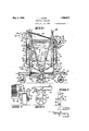
Othe objects and advantages of this inn will be apparent from the following description taken in connection with the accompanying drawings wherein v Fig. lis a side elevation of yimproved device showing the elevating tower in a lowered position. 7
Fig. 2 is a rear end view of Fig. lshowing 1e auxiliary supporting "frame in position.
Fig. is atop plan view oi my device. Fig. *l is an enlarged fragmentary side view of the main frame showing one of the supnor rig Wheels.
5 is an end view of the parts shown in Flg. a. f
Fig. 6 is a section taken on line 6-6" of Fl is an enlarged top plan section taken through one of the columns of theelevating" tower Fig. 8 is an enlarged sectionthrough one of theelevating gears. a
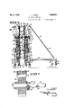
9 a View similar to F 1g. 1- on a reduced scale showing the elevating tower in an extended position, and
F l I is a view similar to 20:1 a reduced scale'showing the elevating tower'in an ext nded position. 7
Referring to the drawings by reference niraclers I have indicated my improved de- 10 coinorises a su oortin frame 11 which L .L
secured thereto, adjacent each end as indivit'e generally at 10. As shown the device oated at 13, an arm leiwhich includes" an angular extension 15. Pivotally secured to the extension 15 as indicated at 16 I provide a forked bearing 17 in which a shaft 18 or a wheel 19is adapted to be rotatably supported (see Figs. 4, 5 and 6). The extension arms 1'6 are adapted to be swung from one side of the members 12a the other and are adaptedto be retained in a desired position by a bolt 20 positioned in apertures 21 (Fig; 4) in the members 12 and in another position by positioning the bolts 20 in aperturesQQ provided in the members'IQ; Thus the width of the tread of the deviee may be altered to suit various conditions. 7 I
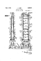
Secured intermediate the length'iof each of the members 11 I provide spaced upright members 24, each pair ofwhich. are secured together adjacent their lower ends by a connecting member 25 and themembers 25 are in turn secured together by transverse members 26 which engage the lower ends of the uprights 24- and are secured thereto as by welding. The uprights 24:1 are further connected by transverse members 27 secured thereto and QHWlliCh is mounted'a platform 28' ad'aptedto support an engine 30. The uprights 24 are also connected by transverse members 31 having longitudinal members 32 secured thereto. I} V v $0 rls clearlyshow'n' in Fig. 7 each of the uprights 24 has a slide 34L secured thereto by rivets 35. Theslide 34' includes opposite'bearing surfaces 36 on each of which is provided a bead 37. v Besides the upright members 24 which are stationary relative to. the frame the elevating tower includesa plurality of sets of movable members 885 shown with three of the members ineachls'et and with the sets four in number but more or loss; may be used de pending on the height to which it is desired to have thetower rise. The mei'nbe'rs 38 are preferably channel shapedand each one except the one'furthe'st removedfromthe meinber 24 has a slide 40 secured thereto by rivets all similar to the slide" 34. These slideslO each include bearing"surfaces 42'on each of which isprovide'd a head 4?; which g lier with the bead were each pesiaoneuir a groove 44 provided in the adjacent surfaces of the members 38.
For steadying the members 38 when they are raised I provide transverse braces 45 adjacent the top of each set. These braces are connected by longitudinal braces 46.
For raising the movable members 88 I provide a gear toothed rack 47 on the outer end of each member. These racks 47' are shown as secured in place by rivets 48. For elevating each set of these racks 47 I provide a gear 50, one of which is shown in detail in Fig. 8. The pair of gears 50 at each end of the machine are each mounted on a shaft 51. The shafts 51 are supported in bearings 52 secured to the stationary upright members 24 as clearly shown in Fig. 2.
The gears 50 are slidably mounted on the shafts 51 and are each provided with a key 53 which is positioned in a k-eyway 54 of the associated shaft whereby rotation of the shaft will be imparted to the gear. For retaining the gears 50 in correct position adjacent their associated racks 47 I provide on each of the gears a spring pressed plunger 55 which is adapted to be positioned consecutively in plurality of recesses 56 in the shaft 51 on which it is mounted.
Secured to one end of each of the shafts 51 I provide mitre gears 57 which are adapted to mesh with mitre pinions 58 secured to a'shaft 59 which is mounted in bearings 60 secured to two of the stationary uprights 24.
Positioned on one/of the shafts 51 I provide a chain hoist which is indicated general.- ly at 62 and may be of any desired type. Thus it will be seen that when the chain hoist 62 is operated both of the shafts 51 will be operated in unison through the medium of the shaft 59 and the gears 57 and pinions 58.
Removably positioned on the frame 11 I provide a tank or trough 63, in which the material to be elevated is deposited in any suitable manner.
For elevating material from the tank 63 I provide a conveyer indicated generally at 65. As shown the conveyer includes a pair of spaced chains 66 which are supported on up per pairs of sprockets 68 and69, intermediate pairs of sprockets 70 and 71 and lower pairs of sprockets 72. The lower sprockets 7 2 are mounted on'a shaft 73 positioned in bearings 74 secured to the frame side mem bers 12 and the intermediate pairs of sprockets 7 O and 71 are mounted on shafts 7 5 and "5' respectivelywhich are positioned in bearings? 6 adjustably secured to the stationary upright members 24 by bolts 77' positioned in elongated apertures 78 in the bearings (see Fig. 2). The upper pairs-of sprockets 68 and 69 are mounted on shafts 80 positioned in bearings 81 whichare secured to the innermost members 38 as clearly shown in Fig. 2.
' Secured to the chains 66 at spaced intervals I provide a plurality of bucket elements which are indicated generally at 83. As shown, each of the bucket elements 83 includes a bracket 84 which includes side members 85 each of which is secured to the adjacent chain 66 at two points as indicated at 86. The members 85 are connected together by a transverse flange 87 as clearly shown in Fig. 3. Each of the brackets 84 is adapted to support a bucket 88 on the sides of which are provided stud shafts 89 which are adapted to be positioned in slots 90 provided in the bracket 84. The stud shafts 89 are adapted to be retained in position in the slots 90 by bolts 91 and the movement of the bucket relative to the bracket is adapted to be limited by stops 92 and 93 which are adapted to engage portions of the associated bracket.
The engine 30 which may be of any desired type is adapted to drive the conveyer mechanism 65 and as shown this is accomplished through the medium of a clutch 95 and a gear train which includes gears 96, 9'4", 98, and 99, the latter meshing with a gear on the shaft 75. bus when the engine 30 is in operation and the clutch 95 put in engagement the conveyor mechanism will be operated in the direction of the arrows in Fig. 1 and the buckets will be moved downward into the trough 63 where they will be filled with the material therein, which may be concrete, as they pass through the trough. The buckets then move upward and over the sprockets 68 whence they will be tilted and may empty their contents into a hopper 102 removably supported on the innermost movable members 38. I
The hopper 102 is shown as provided with a swinging spout 103 through which the mate rial emptied into the hopper passes. to be deposited into a suitable trough (not shown) for conveyance to the desired position.
The machine 10 shown in the accompanying drawings is intended for use in the construction of concrete dwellings and the height thereof when the elevating tower is in the lowered position as shown in Fig. 1 is such that the machine may be moved under an ordinary door arch and the width of the ma chine when the wheels 19 are in an. inward position as shown in Figs. 2 and 3 issuch that the machine may be used in hallways and pass through door openings.
hen there is suliicient space the wheels 19 are preferably moved to an outer position as previously described, .to provide a wider bearing surface for the machine and when there is a still greater amount of space I preferably employ an auxiliary supporting member indicated generally at 105. As shown the supporting member 105 includes a shaped base 106 the spaced ends of which are removably secured to the frame side menibers 12 by bolts 107. At the apex of the 106 I provide bearings 108 in which is positioned a shaft 109 having a wheel 110 thereon.
From adjacent theape'xof the base 106 I provide braces 112' which are inclined upwardly and are removably secured to adjacent stationary upright-members 24 by bolts 113.
IVhen it is desired to raise the elevating tower the chains 66 are disconnected and a sufficient amount of additional links of chain including additional bucket elements is inserted therein to make up for the height to which it is desired to raise the device. The gears are then positioned so that they mesh with the gear toothed racks 47 on the innermost movable upright members 38 and then the operator raises the four innermost upright members 38 by operating the chain lift 6:2. If it is desired to raise the elevating tower higher the gears 50 are positioned so that they mesh with the gear toothed racks 47 on the center movable upright members 38 which will then be raised when the chain hoist is operated, and if it is desired to raise the elevating tower the entire height the gears 50 are then positioned so that they mesh with the gear toothed racks 47 on the outer movable members 38, whereupon on actuation of the chain hoist 62- they will be raised and all the movable members 38 will be in the position shown in Figs. 9 and 10.
As each set of the movable uprights 88 are raised they are secured to the adjacent upright member by bolts 115 and nuts 116. The bolts 115 are positioned in apertures 117 pro vided in the members 24 and 38 and are also adapted to secure braces 118 to the upright members. These braces 118 act to strengthen the tower when it is in a raised position as shown in FigsLQ and 10. The braces 118 may also be used as a ladder by which an operator may conveniently reach the top or intermediate points of the machine when necessary.
At times it will be necessary to clean out the trough 63 and to facilitate the cleaning thereof I preferably construct my device so that the trough may be removed longitudinally from between the side members 12. By reference to Fig. 3 it will be noted that the parts are so arranged and proportioned that the wheels 19 will not interfere with the removal of the trough and by reference to i Fig. 1 it will be noted that the bucket elements 83 are so spaced that they do not interfere with the removal of the trough when they are positioned as shown in Fig. 1.
From the foregoing description it will be I apparent that I have provided a novel elevating conveyer which is simple in construction and efficient in use. 1
Having thus described my invention, I claim: I
1. In a device of the class described, a base, a tower, means to raise and'lower said tower, a conveyer mechanism associated with said tower, said conveyer mechanism including Spaced end. ess chains having vertical reaches and mcludmg a plurahty of buckets, atrough mounted on saidbase, a hopper mounted on said tower, said trough and hopper beingdisposed between the planes passing through the vertical reaches of said chains and means whereby said buckets convey material from said trough to said hop-per and deposit it therein.
2. In a device. ofthe class described, abase,
rectly above said trough, said hopper and said trough being arranged between said chains and means whereby said buckets convey material from said trough to said hopper and deposit it therein.
3. In a device of the class described, a base, a plurality of wheels supporting said base, a telescopic elevating tower mounted on said base, means to raise and lower said tower, a conveyer mechanism supported by said tower, said conveyer mechanism including a pair of spaced chains, aplurality of lower sprockets and a plurality of upper sprockets supporting said chains, a plurality of buckets mounted on said chains, a trough mounted on said base between said lower sprockets, a hopper mounted on said tower directly above said trough, means whereby said buckets convey material from said trough and discharge it in said'hoppcr and means to drive said conveyer mechanism.
.4. In a device of the class described, a base, said base including spaced side members, a plurality of wheels adapted tov support said base, said wheels being positioned inward of the outer edges of said side members, an elevating tower positioned on said base, said tower including a plurality of stationary members secured to said side members and a plurality of movable members, said sta- 'tionary members being positioned inward of said side members and said movable members being positioned inward of said stationary members, a conveyer mechanism, said conveyer mechanism being supported by said tower, a platform supported by said tower, a power device, said device being mounted on said platform and confined Within the limitsiof said side members, means to drive said conveyer from said device, said drive means being confined within the limits of said side members.
5. In a device of the class described, a base, said base including spaced side members, a plurality of wheels adapted to support said base said wheels being positioned inward of said side members an elevating tower on'said base, said tower being positioned within the limits ofsaidside members, an endless conveyer mechanism supportedby said tower, said conveyer mechanism including a plurality of buckets, a trough, said trough being supported inward of said side members and below the lower working reach of said conveyer mechanism, said buckets being adapted to travel within said trough, certain of said buckets being spaced so that the two lowermost buckets may each be disposed above the trough whereby said trough may be removed longitudinally either way on a horizontal plane from between said side members without disturbing said buckets, and said wheels being position below said trough so that they form no hindrance to the removal of said trough.
6. In a device of the class described, abase, an elevating tower mounted on said base, said tower including a plurality of stationary members and a plurality of movable members, a conveyer mechanism supported by said tower, said conveyer mechanism including a pair of spaced chains, said chains adjacent the lower portion of said conveyer being positioned 011 a plurality of sprockets supported by said stationary members, and said chains adjacent the upper portion of said conveyer being positioned on a plurality of sprockets supported by some of said movable members, means to elevate said movable members and means to retain said movable members in a raised position, said conveyer mechanism including a plurality of bucket elements, each of said elements including a section of said chain, a pair of spaced frames se: cured to each of said sections, means connecting each pair of said frames, a bucket removably secured to each pair of said frames, said chains being adapted to be disconnected and the required number of additional sections inserted therein to allow said tower to be raised and said conveyer mechanism to operate.
7 In a device of the class described, a base, a plurality of wheels supporting said base, an elevating tower, said elevating tower including a plurality of stationary upright members secured to said base, a plurality of movable upright members adjacent said stationary members, some of said movable members being in sliding engagement with said stationary members and other of said movable members being in sliding engagement with each other, means to raise and lower said movable members, said means including gear toothed racks on said movable members, a plurality of gears mounted on said stationary members and adapted to engage said racks, means to actuate all of said gears simultaneously, a conveyer mechanismsupported by said tower,'said conveyer mechanism including a plurality of buckets, a trough mounted on said base, a hopper mounted on certain of said movable members, said buckets being adapted to convey material from said trough to said hopper and deposit it therein, a platform supported by said stationary members above said trough, an engine mounted on said platform and means connecting said engine and said conveyer mechanism on said platform and means connecting said engine and said conveyer mechanism whereby said engine drives said conveyer mechanism.
8. In a device of the class described, a base, an elevating tower, said elevating tower including a plurality of stationary, upright members secured to said base, a plurality of movable members adjacent said stationary members, certain of said movable members being in sliding engagement with said stationary members and other of said movable members being in sliding engagement with each other, means to raise and lower said movable members, said means including gear toothed racks on said movable members and a plurality of gears mounted on said stationary members and adapted to engage said racks and means to actuate all of said gears simultaneously, a conveyer mechanism supported by said tower, said conveyer mechanism including a pair of spaced chains, a plurality of lower sprockets and a plurality of upper sprockets supporting said chains, said lower sprockets being mounted on said stationary members and said upper sprockets being mounted on some of said movable members, a plurality of buckets mounted on said chains, a trough mounted on said base, a hopper mounted on some of said movable members, said buckets being adapted to convey material from said trough to said hopper and deposit it therein and means to drive said conveyer mechanism.
9. In a device of the class described, a base, a plurality of wheels supporting said base, an elevating tower, said elevating tower including a plurality of stationary upright members secured to said base, a plurality of movable upright members adjacent said stationary members, some of said movable members being in sliding engagement with said stationary members, means to raise and lower said movable members, said means including gear toothed racks on said movable members and a plurality of gears mounted on said stationary members and adapted to engage said racks and means to actuateall of said gears simultaneously, means to secure adjacent movable members together when in a raised position, a conveyer mechanism supported by said tower, said conveyer mechanism including a pair of spaced chains, said lower sprockets being mounted on said stationary members and said upper sprockets being mounted on some of said movable members, a plurality of buckets mounted on said chains, a trough mounted on said base, a hopper mounted on some of said movable members, said buckets being adapted to convey material from said trough to said hopper and deposit it therein, a platform supported by said stationary members above said trough,
an engine mounted on said platform and means connecting said engine and said conveyer mechanism whereby said engine drives said conveyer mechanism, said connecting means including a clutch mechanism.
In testimony whereof, I hereunto affix my signature.
IRA J. KUERT.
Priority Applications (1)
| Application Number | Priority Date | Filing Date | Title |
|---|---|---|---|
| US401685A US1856873A (en) | 1929-10-23 | 1929-10-23 | Elevating conveyer |
Applications Claiming Priority (1)
| Application Number | Priority Date | Filing Date | Title |
|---|---|---|---|
| US401685A US1856873A (en) | 1929-10-23 | 1929-10-23 | Elevating conveyer |
Publications (1)
| Publication Number | Publication Date |
|---|---|
| US1856873A true US1856873A (en) | 1932-05-03 |
Family
ID=23588778
Family Applications (1)
| Application Number | Title | Priority Date | Filing Date |
|---|---|---|---|
| US401685A Expired - Lifetime US1856873A (en) | 1929-10-23 | 1929-10-23 | Elevating conveyer |
Country Status (1)
| Country | Link |
|---|---|
| US (1) | US1856873A (en) |
Cited By (3)
| Publication number | Priority date | Publication date | Assignee | Title |
|---|---|---|---|---|
| US2430689A (en) * | 1944-10-27 | 1947-11-11 | Owen L Shook | Lumber handling machine |
| US2533813A (en) * | 1948-05-27 | 1950-12-12 | Joseph M Jones | Tobacco elevator |
| US2552136A (en) * | 1945-06-13 | 1951-05-08 | Gen Electric | Linear amplifier system |
-
1929
- 1929-10-23 US US401685A patent/US1856873A/en not_active Expired - Lifetime
Cited By (3)
| Publication number | Priority date | Publication date | Assignee | Title |
|---|---|---|---|---|
| US2430689A (en) * | 1944-10-27 | 1947-11-11 | Owen L Shook | Lumber handling machine |
| US2552136A (en) * | 1945-06-13 | 1951-05-08 | Gen Electric | Linear amplifier system |
| US2533813A (en) * | 1948-05-27 | 1950-12-12 | Joseph M Jones | Tobacco elevator |
Similar Documents
| Publication | Publication Date | Title |
|---|---|---|
| US1128671A (en) | Lumber stacker and unloader. | |
| US2407782A (en) | Tray stacker | |
| US1856873A (en) | Elevating conveyer | |
| US2200274A (en) | Portable crane | |
| US3437174A (en) | Mobile platform construction | |
| US897462A (en) | Portable stacking-elevator. | |
| US1736472A (en) | Tray elevator | |
| US2368414A (en) | Inclined elevator | |
| US1557776A (en) | Elevating and lowering conveyer | |
| US1916517A (en) | Lifting jack | |
| US683124A (en) | Elevating-stairway. | |
| US1923663A (en) | Machinery for handling chassis frames | |
| US815416A (en) | Elevating-truck. | |
| US1804287A (en) | Material handling apparatus | |
| US1031850A (en) | Grain-handling device. | |
| US1592069A (en) | Elevating conveyer | |
| US1597961A (en) | Brick machine | |
| US1815429A (en) | Garage | |
| US2884721A (en) | Excavating apparatus | |
| US1613923A (en) | Loading machine | |
| US342685A (en) | Fireman s extension-ladder | |
| US1432917A (en) | Portable bucket conveyer | |
| US1884671A (en) | Loading machine | |
| US2071743A (en) | Beet piling machine | |
| US357234A (en) | Lifting apparatus |