US1856861A - Blasting cartridge - Google Patents
Blasting cartridge Download PDFInfo
- Publication number
- US1856861A US1856861A US398043A US39804329A US1856861A US 1856861 A US1856861 A US 1856861A US 398043 A US398043 A US 398043A US 39804329 A US39804329 A US 39804329A US 1856861 A US1856861 A US 1856861A
- Authority
- US
- United States
- Prior art keywords
- electrode
- cartridge
- wall
- valve
- passage
- Prior art date
- Legal status (The legal status is an assumption and is not a legal conclusion. Google has not performed a legal analysis and makes no representation as to the accuracy of the status listed.)
- Expired - Lifetime
Links
- 238000005422 blasting Methods 0.000 title description 11
- 238000010276 construction Methods 0.000 description 7
- 238000004891 communication Methods 0.000 description 5
- 238000010304 firing Methods 0.000 description 5
- 239000004020 conductor Substances 0.000 description 3
- 238000012856 packing Methods 0.000 description 3
- 238000013022 venting Methods 0.000 description 2
- 230000005611 electricity Effects 0.000 description 1
- 239000012530 fluid Substances 0.000 description 1
- 239000011810 insulating material Substances 0.000 description 1
Images

Classifications
-
- F—MECHANICAL ENGINEERING; LIGHTING; HEATING; WEAPONS; BLASTING
- F42—AMMUNITION; BLASTING
- F42B—EXPLOSIVE CHARGES, e.g. FOR BLASTING, FIREWORKS, AMMUNITION
- F42B3/00—Blasting cartridges, i.e. case and explosive
- F42B3/04—Blasting cartridges, i.e. case and explosive for producing gas under pressure
- F42B3/06—Blasting cartridges, i.e. case and explosive for producing gas under pressure with re-utilisable case
Definitions
- This invention relates to blasting cartridges of the general type shown in pending application Serial No. 356,360, filed April 19, 1929. More particularly, the invention is concerned with improvements in the construction, mounting and relationships of the valve and electrode elements of such a cartridge.
- An object of the invention is to provide an efficient and reliable cartridge of the character indicated.
- Another object of the invention is to simplify and increase the reliability of the valve and electrode elements of blasting cartridges of the type indicated.
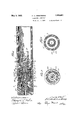
- Figure 1 is a longitudinal sectional view of one form of construction embodying my invention.
- Figures 2 and 3 are transverse sectional views taken on line 2-2 and 3-3 respectively of Figure 1.
- Figure 4 is a longitudinal r'sectional view of a second form of construction embodying my invention.
- Figures 5 and 6 are transverse sectional views taken on lines 5 5 and 6-6 respectively of Figure 4.
- a blasting cartridge of the type to which the present improvements are applied may consist of a substantially cylindrical body or shell l having an internal gas chamber 2 and a discharge opening 3.
- the discharge end ofthe cartridge may be provided with any suitable form of pressure responsive venting means.
- the usual form of venting means employed in connection with cartridges of this type is a rupturable disc positioned over the open end 3 of the cartridge and held securely thereagainst by means of a shear ring and a discharge cap which has threaded connection with the shell body as indicated by 4.
- the discharge mechanism is not herein shown as it forms no part of the present invention.
- the opposite end of the gas chamber is defined by transverse wall 5, beyond which extends a sleeve 6.
- the wall 5 is centrally perforated and an electrode 7 is positioned through this perforation.
- a flange 8 formed on the electrode is positioned adjacent the outer face of the wall 5,'but is insulated therefrom by means of an insulating disc 9.
- An annular band of insulating material surrounds the electrode at the point where it passes through the wall 5.
- the inner end of the electrode which is positioned within the Oas chamber is provided with screw threads adaptedto be associated with corresponding threads formed internally of a heater support 12. Interposed between the inner face of the wall 5 and the adjacent end face of the electrode 12 is an insulating and packing disc 11.
- the heater support is centrally recessed at its free end as indicated at 13 and this recess is provided withr a substantially conical approach in order to facilitate the entering of a tubular heater unit therein.
- Notches 15 are provided in the end of the heater support for the reception of a suitably formed pin wrench vwhich may be used to assemble the heater support upon the electrode and to tighten the same against the packing and insulating disc l1. It will be appreciated that the tightening of the heater support serves to draw both the flange 8 of the electrode and the heater support toward the interposed wall 5, thus compressing the insulating and packing elements 9 and 11 whereby to provide an effective seal against the escape of gas from the chamber.
- the inner end of the electrode terminates short of the bottom of the pocket formed in the heater support, thereby forming a small chamber between the end face of the electrode and the bottom wall of the recess.
- a gas passage 16 extends axially entirely through the electrode and communicates with the small gas chamber formed in the heater support.
- One or-more transverse ports are provided in the heater support to place the chamber thereof in communication with the main gas chamber ofthe cartridge.
- valve body 18 Threaded on the outer end of the electrode is a valve body 18 in which is centrallypositioned an axially adjustable valve stem 19 which has a substantially conical end for cooperation with a conical seat formed in the axially toward contacting position.
- Gas may be introduced into the cartridge through a suitable passage 2O in the valve body when the valve stem 19 is withdrawn from engagement with the valve seat on the electrode and when the desired charge has been introduced into the cartridge, the valve 19 may be moved axially to seal the end of the gas passage 1G, thus trapping the charge that has been formed in the cartridge.
- An aperture 21 is provided in the shellbody 1 in transverse alignment with the aperture 2O in the valve body for the purpose of receiving a charging nozzle.
- a short circuiting device which consists of a cylindrical sleeve 22 having an inwardly extending flange adapted to make contact with one or more contacts 23 formed ou the valve body.
- the sleeve 22 has electrical connection with the shell body through the medium of a coil spring 24 which also serves to move the sleeve
- the disengagement of this sleeve is effected by the firing plug 25 which is provided with a sleeve like portion 26 so proportioned that when the plug is inserted inthe end of the cartridge the sleeve 26 engages the sleeve 22 and moves the same out of engagement with the contacts 23.
- the firing plug is provided with lugs 27 which cooperate with bayonet slots 28 formed in the end of the cartridge body to form a detachable connection therewith.
- a metallic plug 29 is disposed within a central recess in the firing plug, but is insulated therefrom by means of the insulating cup 30.
- the member 29 is provided with an axial passage in which an electric conductor may be secured, and in alignment with this passage isl an insulated opening 31 formed in the firing plug.
- the circuit between the member 29 and the electrode is completed by means of a metallic spring 32 which engages member 29 and the valve body.
- a second electric conductor may be secured directly to the firing plug 25 by means or' the aperture 33 and set screw 34.
- one conductor is electrically connected to the cartridge body through the medium of the metallic iring plug and lugs 27 thereon which engage the shell body and the other conductor-is insulated with respect to the tiring plug but is placed in electrical connection with electrode through the medium of the metallic plug 29,
- FIG. 4 The construction shown in Figures 4, 5 and 6 is for the most part the saine 'as that shown flange formed on said electrode adjacent the" outer face of saidwall, a. heater support in Figures l, 2 and 3, but embodies a somewhat different type of valve mechanism.
- the outer end of the electrode is formed with a cylindrical recess as indicated at 19 and disposed within this recess is the head 19 of a valve stem 20.
- Stem 2O is screw threaded through the valve body 18 which, in turn, is screw threaded on the outer end of the electrode.
- the valve stem is provided with an axial passage 21 which extends from its outer end to and in communication with a transverse passage 22l located short of the extreme inner end of the stem.
- rIhe passagev 22 is in .communication with the chamber formed by the head 19 of the stem and the bottom wall of the cylindrical recess 19" in the electrode.
- kThe extreme ⁇ inner yend 23 of the valve stem is of substantially conical form for cooperation with a correspondingly formed seat in the end of the passage 16.
- a nozzle seat 24 is provided intheouter end of the valve stem in communication ,with the passage 21. With this construction gas may be introduced axially throughthe valve stem and may pass through the electrode when the stem is adjusted outwardly to remove the conical end 23 thereof from engagement with the electrode.
- T he construction shown in Figure 4 dii'ers fur-ther from that shown in Figures 1 2 ⁇ and 3only in that the short circuiting device is in the form of a disc 25 rather than av sleeve with an inwardly extending flange as in Figure 1.
- a blasting cartridge comprising a metallic body having an internal gaschamber formed therein, Aan electrode extending through an aperture in a wall of said body,a
- a blasting cartridge comprising ame.-V tallic body having an internal gas chamber formed therein, van electrode extending' through an aperture in a wall ofsaid body,
- Van insulating sleeve surrounding said electrode within the aperture, a ange formed on said electrode adjacent the outer faceofsaid wall, an insulating discinterposed between said flange and wall, a nut threaded on the in- -ner end of said electrode and adapted to clamp said flange and disc against said wall, an insulating disc interposed between the inner face of said wall 'and the adjacent end of said nut, and a heater support integral with?V saidnut'.
- a blasting cartridge comprising a-metallic body having an internal gas chamber formed therein, an electrode extendingv thru an aperture in a wall :of said body, a flange? 'lok formed on said electrode adjacent the outer face of said Wall, a heater support having threaded engagement with the inner end of said electrode and adapted to serve as a nut to draw said flange against said Wall, and means for insulating said electrode from said body, communicating charging passages in said electrode and heater support, and a valve associated With the outer end of said electrode for controlling the admission of fluid to said passage.
- a blasting cartridge comprising a metallic body having an internal gas chamber formed therein, an electrode extending through a Wall of said body and insulated therefrom, a charging passage extending thru said electrode and terminating Within the chamber, a valve cap mounted on the outer end of said electrode, a valve stem adj ustably mounted in said cap and having a substantially conical tipadapted to engage a correspondingly formed seat in the electrode, said valve stem having an axial passage extending from the outer end thereof to a point adjacent the base of the conical tip, and a transverse passage through said tip in communication with said axial passage.
- a blasting cartridge comprising a metallic body having an internal gas chamber formed therein, an electrode extending through a Wall of said body and insulated therefrom, said electrode having a charging passage extending axially therethrough With a substantially conical seat at the outer end of the passage, the outer end of said electrode being Jformed With an axially disposed cylindrical recess, a valve cap mounted on the outer end of said electrode, a valve stern adjustably mounted in said cap and having a substantially conical seat, a substantially cylindrical enlargement formed on said stem adj acent said tip and disposed Within the aforesaid cylindrical recess, the tipof said stem having a transverse passage therethrough opening into said recess and an axial passage extending from the outer end of said stem and communicating With said transverse passage.
Landscapes
- Engineering & Computer Science (AREA)
- General Engineering & Computer Science (AREA)
- Quick-Acting Or Multi-Walled Pipe Joints (AREA)
Description
F. H. ARMSTRONG BLASTING CARTRIDGE May 3, 1932. l
Filed oct. 7, 1929 2 Sheets-Shea?I l .WNN\\\\\\\\\\\.`
May y3, 1932.
F. H: ARMSTRONG BLASTING cARTRInGE Filed Oct. '7, 1929 2 Sheets-Sheet 2 ny/Q 2z/522%@ @w @M wat Patented May 3, 1932 FRANK IBI. ARMSTRONG, OF CHICAGO, ILLINOIS, ASSIGNORKTO SAFETY MINING COM- PANY, 0F CHICAGO, ILLINOIS, A CORPORATION IBLASTING CARTRIDGE Application led October 7, 1929. Serial No. 398,043.
This invention relates to blasting cartridges of the general type shown in pending application Serial No. 356,360, filed April 19, 1929. More particularly, the invention is concerned with improvements in the construction, mounting and relationships of the valve and electrode elements of such a cartridge.
An object of the invention is to provide an efficient and reliable cartridge of the character indicated.
Another object of the invention is to simplify and increase the reliability of the valve and electrode elements of blasting cartridges of the type indicated.
These and other objects are realized by the invention exemplied by the structures shown in the accompanying drawings.
In the drawings,
Figure 1 is a longitudinal sectional view of one form of construction embodying my invention.
Figures 2 and 3 are transverse sectional views taken on line 2-2 and 3-3 respectively of Figure 1.
Figure 4 is a longitudinal r'sectional view of a second form of construction embodying my invention, and
Figures 5 and 6 are transverse sectional views taken on lines 5 5 and 6-6 respectively of Figure 4.
A blasting cartridge of the type to which the present improvements are applied may consist of a substantially cylindrical body or shell l having an internal gas chamber 2 and a discharge opening 3. The discharge end ofthe cartridge may be provided with any suitable form of pressure responsive venting means. The usual form of venting means employed in connection with cartridges of this type is a rupturable disc positioned over the open end 3 of the cartridge and held securely thereagainst by means of a shear ring and a discharge cap which has threaded connection with the shell body as indicated by 4. The discharge mechanism is not herein shown as it forms no part of the present invention.
The opposite end of the gas chamber is deined by transverse wall 5, beyond which extends a sleeve 6. The wall 5 is centrally perforated and an electrode 7 is positioned through this perforation. A flange 8 formed on the electrode is positioned adjacent the outer face of the wall 5,'but is insulated therefrom by means of an insulating disc 9. An annular band of insulating material surrounds the electrode at the point where it passes through the wall 5. The inner end of the electrode which is positioned within the Oas chamber is provided with screw threads adaptedto be associated with corresponding threads formed internally of a heater support 12. Interposed between the inner face of the wall 5 and the adjacent end face of the electrode 12 is an insulating and packing disc 11. The heater support is centrally recessed at its free end as indicated at 13 and this recess is provided withr a substantially conical approach in order to facilitate the entering of a tubular heater unit therein. Notches 15 are provided in the end of the heater support for the reception of a suitably formed pin wrench vwhich may be used to assemble the heater support upon the electrode and to tighten the same against the packing and insulating disc l1. It will be appreciated that the tightening of the heater support serves to draw both the flange 8 of the electrode and the heater support toward the interposed wall 5, thus compressing the insulating and packing elements 9 and 11 whereby to provide an effective seal against the escape of gas from the chamber.
From Figure l of the drawings it will be noted that the inner end of the electrode terminates short of the bottom of the pocket formed in the heater support, thereby forming a small chamber between the end face of the electrode and the bottom wall of the recess. A gas passage 16 extends axially entirely through the electrode and communicates with the small gas chamber formed in the heater support. One or-more transverse ports are provided in the heater support to place the chamber thereof in communication with the main gas chamber ofthe cartridge.
Threaded on the outer end of the electrode is a valve body 18 in which is centrallypositioned an axially adjustable valve stem 19 which has a substantially conical end for cooperation with a conical seat formed in the axially toward contacting position.
outer end of the passage 16. Gas may be introduced into the cartridge through a suitable passage 2O in the valve body when the valve stem 19 is withdrawn from engagement with the valve seat on the electrode and when the desired charge has been introduced into the cartridge, the valve 19 may be moved axially to seal the end of the gas passage 1G, thus trapping the charge that has been formed in the cartridge. An aperture 21 is provided in the shellbody 1 in transverse alignment with the aperture 2O in the valve body for the purpose of receiving a charging nozzle. l
It has been found desirable in some types of cartridges to provide a means whereby the electrode and shell body are normally short circuited until such time as the cartridge is ready to be discharged, in ord-er to prevent accidental discharge by reason of stray currents or the accidental engagement of the cartridge with exposed Sources of electricity. To this end, there is herein shown a short circuiting device which consists of a cylindrical sleeve 22 having an inwardly extending flange adapted to make contact with one or more contacts 23 formed ou the valve body. The sleeve 22 has electrical connection with the shell body through the medium of a coil spring 24 which also serves to move the sleeve The disengagement of this sleeve is effected by the firing plug 25 which is provided with a sleeve like portion 26 so proportioned that when the plug is inserted inthe end of the cartridge the sleeve 26 engages the sleeve 22 and moves the same out of engagement with the contacts 23. The firing plug is provided with lugs 27 which cooperate with bayonet slots 28 formed in the end of the cartridge body to form a detachable connection therewith. A metallic plug 29 is disposed within a central recess in the firing plug, but is insulated therefrom by means of the insulating cup 30. The member 29 is provided with an axial passage in which an electric conductor may be secured, and in alignment with this passage isl an insulated opening 31 formed in the firing plug. The circuit between the member 29 and the electrode is completed by means of a metallic spring 32 which engages member 29 and the valve body. A second electric conductor may be secured directly to the firing plug 25 by means or' the aperture 33 and set screw 34. Thus, one conductor is electrically connected to the cartridge body through the medium of the metallic iring plug and lugs 27 thereon which engage the shell body and the other conductor-is insulated with respect to the tiring plug but is placed in electrical connection with electrode through the medium of the metallic plug 29,
the spring 32 and the valve body 18.
The construction shown in Figures 4, 5 and 6 is for the most part the saine 'as that shown flange formed on said electrode adjacent the" outer face of saidwall, a. heater support in Figures l, 2 and 3, but embodies a somewhat different type of valve mechanism. In this construction the outer end of the electrode is formed with a cylindrical recess as indicated at 19 and disposed within this recess is the head 19 of a valve stem 20. Stem 2O is screw threaded through the valve body 18 which, in turn, is screw threaded on the outer end of the electrode. The valve stem is provided with an axial passage 21 which extends from its outer end to and in communication with a transverse passage 22l located short of the extreme inner end of the stem. rIhe passagev 22 is in .communication with the chamber formed by the head 19 of the stem and the bottom wall of the cylindrical recess 19" in the electrode. kThe extreme` inner yend 23 of the valve stem is of substantially conical form for cooperation with a correspondingly formed seat in the end of the passage 16.
A nozzle seat 24 is provided intheouter end of the valve stem in communication ,with the passage 21. With this construction gas may be introduced axially throughthe valve stem and may pass through the electrode when the stem is adjusted outwardly to remove the conical end 23 thereof from engagement with the electrode. Y
T he construction shown in Figure 4 dii'ers fur-ther from that shown in Figures 1 2`and 3only in that the short circuiting device is in the form of a disc 25 rather than av sleeve with an inwardly extending flange as in Figure 1.
I claimt` Q 1 1. A blasting cartridge comprising a metallic body having an internal gaschamber formed therein, Aan electrode extending through an aperture in a wall of said body,a
having threaded engagement with theinner endof said electrode and adapted to serve as .a nut to draw said flange against said wall,
and means for insulating` said electrode from; 'said body. j Y n A 2. A blasting cartridge comprising ame.-V tallic body having an internal gas chamber formed therein, van electrode extending' through an aperture in a wall ofsaid body,
Van insulating sleeve surrounding said electrode within the aperture, a ange formed on said electrode adjacent the outer faceofsaid wall, an insulating discinterposed between said flange and wall, a nut threaded on the in- -ner end of said electrode and adapted to clamp said flange and disc against said wall, an insulating disc interposed between the inner face of said wall 'and the adjacent end of said nut, and a heater support integral with?V saidnut'. Y 1
3. A blasting cartridge comprising a-metallic body having an internal gas chamber formed therein, an electrode extendingv thru an aperture in a wall :of said body, a flange? 'lok formed on said electrode adjacent the outer face of said Wall, a heater support having threaded engagement with the inner end of said electrode and adapted to serve as a nut to draw said flange against said Wall, and means for insulating said electrode from said body, communicating charging passages in said electrode and heater support, and a valve associated With the outer end of said electrode for controlling the admission of fluid to said passage.
4. A blasting cartridge comprising a metallic body having an internal gas chamber formed therein, an electrode extending through a Wall of said body and insulated therefrom, a charging passage extending thru said electrode and terminating Within the chamber, a valve cap mounted on the outer end of said electrode, a valve stem adj ustably mounted in said cap and having a substantially conical tipadapted to engage a correspondingly formed seat in the electrode, said valve stem having an axial passage extending from the outer end thereof to a point adjacent the base of the conical tip, and a transverse passage through said tip in communication with said axial passage.
5. A blasting cartridge comprising a metallic body having an internal gas chamber formed therein, an electrode extending through a Wall of said body and insulated therefrom, said electrode having a charging passage extending axially therethrough With a substantially conical seat at the outer end of the passage, the outer end of said electrode being Jformed With an axially disposed cylindrical recess, a valve cap mounted on the outer end of said electrode, a valve stern adjustably mounted in said cap and having a substantially conical seat, a substantially cylindrical enlargement formed on said stem adj acent said tip and disposed Within the aforesaid cylindrical recess, the tipof said stem having a transverse passage therethrough opening into said recess and an axial passage extending from the outer end of said stem and communicating With said transverse passage.
Signed at Chicago, Illinois, this 3rd day or October, 1929.
FRANK H. ARMSTRONG.
Priority Applications (1)
| Application Number | Priority Date | Filing Date | Title |
|---|---|---|---|
| US398043A US1856861A (en) | 1929-10-07 | 1929-10-07 | Blasting cartridge |
Applications Claiming Priority (1)
| Application Number | Priority Date | Filing Date | Title |
|---|---|---|---|
| US398043A US1856861A (en) | 1929-10-07 | 1929-10-07 | Blasting cartridge |
Publications (1)
| Publication Number | Publication Date |
|---|---|
| US1856861A true US1856861A (en) | 1932-05-03 |
Family
ID=23573766
Family Applications (1)
| Application Number | Title | Priority Date | Filing Date |
|---|---|---|---|
| US398043A Expired - Lifetime US1856861A (en) | 1929-10-07 | 1929-10-07 | Blasting cartridge |
Country Status (1)
| Country | Link |
|---|---|
| US (1) | US1856861A (en) |
-
1929
- 1929-10-07 US US398043A patent/US1856861A/en not_active Expired - Lifetime
Similar Documents
| Publication | Publication Date | Title |
|---|---|---|
| US3081701A (en) | Smoke candle and cup discharger for firing the smoke candle | |
| US1856861A (en) | Blasting cartridge | |
| US2881363A (en) | Spark type heater igniter | |
| US2343276A (en) | Device for inflating balloons and the like | |
| US2056739A (en) | Explosionproof shielded spark plug | |
| US2210192A (en) | Gun perforator | |
| US2731079A (en) | Apparatus for atomizing and igniting substances | |
| US2496160A (en) | Hand fire extinguisher | |
| US2069046A (en) | Spark plug shield | |
| US1998710A (en) | Ignition system | |
| US2200487A (en) | Bullet type casing perforator | |
| US1826702A (en) | Blasting cartridge | |
| US1645638A (en) | Shot loader | |
| US1807144A (en) | Blasting cartridge | |
| US1829847A (en) | Safety blasting device | |
| US1818995A (en) | Blasting cartridge | |
| US2216151A (en) | Gun type well casing perforator | |
| US1805541A (en) | Blasting cartridge | |
| US2405125A (en) | Automatic fire extinguisher | |
| US1821608A (en) | Blasting cap | |
| US1856871A (en) | Blasting cartridge | |
| US1552352A (en) | Spark plug | |
| US1024601A (en) | Terminal-attachment-engaging device. | |
| US1517385A (en) | Fuse holder | |
| US1857792A (en) | Blasting cartridge |