US1856832A - Circuit controller - Google Patents
Circuit controller Download PDFInfo
- Publication number
- US1856832A US1856832A US420348A US42034830A US1856832A US 1856832 A US1856832 A US 1856832A US 420348 A US420348 A US 420348A US 42034830 A US42034830 A US 42034830A US 1856832 A US1856832 A US 1856832A
- Authority
- US
- United States
- Prior art keywords
- cam
- switch
- support
- drum
- circuit
- Prior art date
- Legal status (The legal status is an assumption and is not a legal conclusion. Google has not performed a legal analysis and makes no representation as to the accuracy of the status listed.)
- Expired - Lifetime
Links
- 241001131688 Coracias garrulus Species 0.000 description 14
- 238000010276 construction Methods 0.000 description 5
- 239000000463 material Substances 0.000 description 4
- 230000011664 signaling Effects 0.000 description 3
- 239000011810 insulating material Substances 0.000 description 2
- 230000004048 modification Effects 0.000 description 2
- 238000012986 modification Methods 0.000 description 2
- 230000010355 oscillation Effects 0.000 description 2
- 101150000595 CLMP gene Proteins 0.000 description 1
- 101100382322 Drosophila melanogaster Acam gene Proteins 0.000 description 1
- 239000004020 conductor Substances 0.000 description 1
- 238000005192 partition Methods 0.000 description 1
Images


Classifications
-
- G—PHYSICS
- G08—SIGNALLING
- G08G—TRAFFIC CONTROL SYSTEMS
- G08G1/00—Traffic control systems for road vehicles
- G08G1/07—Controlling traffic signals
- G08G1/085—Controlling traffic signals using a free-running cyclic timer
-
- Y—GENERAL TAGGING OF NEW TECHNOLOGICAL DEVELOPMENTS; GENERAL TAGGING OF CROSS-SECTIONAL TECHNOLOGIES SPANNING OVER SEVERAL SECTIONS OF THE IPC; TECHNICAL SUBJECTS COVERED BY FORMER USPC CROSS-REFERENCE ART COLLECTIONS [XRACs] AND DIGESTS
- Y10—TECHNICAL SUBJECTS COVERED BY FORMER USPC
- Y10T—TECHNICAL SUBJECTS COVERED BY FORMER US CLASSIFICATION
- Y10T74/00—Machine element or mechanism
- Y10T74/21—Elements
- Y10T74/2101—Cams
- Y10T74/2102—Adjustable
- Y10T74/2104—Flexible strip
Definitions
- cocoon m AN 0 6000000000000000000000oooocooooonooq ⁇ k u 00.000000000000000 ooooocoooocooooocno xofiovoocooocouooooooooooo oooooodooococoooooo QASC 0O0000000000000OOOOQOOOOOODOOOGOOOOOO0000OOOOOOOOOQOGOOOOOOOOOOQ 2$ r ⁇ oooooooooocoooo cooooooooooco cooooooucooooooooooooq ocooooooooooooocooooocoocoooocoooooooooooouoo0o0ooaooooooooQ2 Maya, 1932.
- One object of my invention is to provide a controller in which any suitable number of comparatively simple and readily adjustable cams can be readily provided for controlling corresponding circuits.
- a further object of my invention is to provide a controller with means for operating any signal of a large group independently during any portion of a cycle.
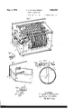
- Fig. 1 shows more or less diagrammatically a controller comprising the features of the invention in a trafiic signaling system.
- Fig. 2 shows in perspective the controller of Fig. 1 in full, located in its frame.
- Fig. 3 shows the base and a support for the controller hinged thereon, the support being shown swung out and in perspective.
- Fig. 4 is a transverse sectional view of the controller and shows the relation of one of the make and break contact switch devices for one of the signal circuits and the drum controller elements for operating said contact device.
- Fig. 5 shows the elements of the contact device of Fig. 4 separated to more clearly show the details of its construction.
- Fig. 1 shows more or less diagrammatically a controller comprising the features of the invention in a trafiic signaling system.
- Fig. 2 shows in perspective the controller of Fig. 1 in full, located in its frame.
- Fig. 3 shows the base and a support for the controller hinged thereon, the support being shown sw
- FIG. 6 shows diagrammaticallya develo ment of the drum controller, Fig. 2, in whic four signal circuits and two reset circuits, or six circuits all told, are involved.
- Fig. 7 shows diagrammatically the development of a drum controller similar to that of Fig. 6, in which eight signal circuits and two reset circuits, or ten circuits all told, are used;
- Fig. 8 shows a similar development for nine signal circuits and two reset circuits, or eleven circuits in all;
- Fig. 9 shows the construction of the pin in the arm that drives the drum of the controller; and
- Figs. 10 and 11 show two views of amodified form of cam construction for the controller.
- the controller Fig. 2 comprises a rotatable drum 15 which is provided with a series of .cams a through 7'.
- Each of these cams is preferably made of flexible material, such as for example, coiled spring wire in the form of a flexible ring, see Fig. 4.
- Each of these cams has associated with it a corresponding ring of teeth through 34 on the drum for cams a through 7'.
- the controller is also provided with a set of springs16, 17, 14', 19 through 23, 11 and 24, each of which forms part of a make and break contact switch adapted to be connected-in circuit with any suitable device such as a signal. This is diagrammatically shown in Fig. 1.
- the springs 16, 17, 14 and 19 are shown connected with a set of traflic signals R, A, G, (indicating respectively red-ambereen) at the intersection of streets X and Y.
- F ach of these springs is provided with an arm and with a roller on the end thereof, which latter is adapted to ride on the corresponding cam.
- the spring 16 is provided with an arm 35 and with a roller 45 on the end thereof, which latter is adapted to ride on the cam a, see Fig. 4.
- the arm is shown secured to the spring, but thepreferred arrangement is shown in Fig. 5 where the spring 16 is shown secured to a body 63 of insulating material loosely 1nount ed on a shaft 62.
- arm 35 is shown secured to a body of insulating material 35/1, also loosely /mounted on the shaft 62, which latter is common to all the springs operated by the cams on the drum 15.
- the body 35a is provided with a pin 64, which, when the elements 63 and 35a are drawn together. as shown in Fig. 2, enters into a hole 64, thus interlocking the two elements.
- the arm 35 is secured in an suitable manner and on the lower end oft e latter the roller 45 is located in a position to engage its corresponding cam a.
- a spring 65 is shown interposed between the rear end of the elements 63 and the frame 68.
- the object of this spring is to give the element 63 a tendency to rotate in a clockwise direction as viewed in Fig. 4 so that when the roller 45 leaves the cam the spring 16 is carried into engagement with the corresponding contact 69 in the light signaling circuit. Obviously with the construetion shown any movement of the arm 35 will cause a corresponding movement of the sprin 16 about the shaft 62.
- a so-called reset relay R which is no part of the present invention, but which is adapted to be energized or deenergized in any suitable manner from a distant point.
- the object of this relay is to shift the relay spring 47 back and forth between the corresponding contacts 50 and 51 for switching the control of the so-called reset circuit to either one or the other of the cam springs 11 or 24, Fig. 2.
- a cam such as the cam a of spring 16 is located on the left side, Fig. 2, of its ring of teeth 25, the cam and the roller 45 will engage and operate the switch element 16; but if the cam is located on the opposite side of its ring of teeth the element 16 cannot be operated thereby.
- the cam a were located entirely on the right side of the ring of teeth the roller 45 would at no time during the rotation of the drum ongage with the cam.
- the cam is flexible, and part of the cam a may be confined to one side of the ring of teeth and the other part may be shifted to the opposite side, as indicated in Figs. 1, 2 and 6, with the result that during part'of each cycle of operation of the drum the roller 45 will ride on the cam a and during the remainder of the cycle it will fail to do so.
- the roller 45 is riding on the portion of the cam a located on the left of the teeth 25, Fig.
- the contact spring 16 will he raised and out of engagement with the corresponding contact 69, and therefore, the circuit through this switch will be broken. ⁇ Vhen the roller 45 leaves the cam, the spring 16 will fall into engagement with the contact 69, thus closing the circuit.
- the adjustment may be varied so that the portions of the cam 011 eapposite sides of its ring of teeth may be vari to assume any one of the various positions indicated in Fig. 6, for example, in connection with the cams a, Z), 0, d, i, 7', or as indicated in Fig. 7 in connection with all of the cams. Therefore, in the diagrammatic illustration of Fi 6, that portion of the cam which is located on the left hand side of the ring of teeth 25 represents an open circuit at the switch 16' through signals'R (N-S) and G (E-W),
- the drum and its coiled springs therefore, form an exceedingly flexible controller, the cams of which may be, with very little effort, changed to assume any desired form so that the interval of closure or of interruption or both of any particular circuit may be changed as the occasion arises without the necessity of having to dismantle any of the apparatus.
- the only thing that is necessary is to stretch the spring forming the cam over the teeth of the drum and shift it into the desired position with respect to its ring of teeth.
- rings of teeth 25 through 34 are shown. These merely serve as partitions and are not essential to the operation of the device. If desired, these teeth may be omitted.
- the means for rotating the drum 15 comprises a supporting shaft 59, which shaft is provided with a toothed wheel 58 adapted to be rotated in the direction indicated by the arrow, Fig. 1, by oscillating an arm 56.
- This latter is provided with pins 56a and 56b adapted to alternately engage the detents 58' on wheel 58 and therebyadvan'ce the wheel i one tooth upon each oscillation of the arm 56, the latter being mounted to oscillate about the axis 57 57.
- the oscillation of this arm is adapted to be plroduced by means of the solenoid magnets l N, which are connected with any suitable source of current G and with an im ulse sender diagrammatically represented y the springs 3 and 4.
- These springs are adapted to e alternately carried into engagement with the contact 5 in any suitable manner, as for example by a pendulum, for alternately energizing the solenoids h N.
- Fig. 9 I have shown here pins that may be substituted for the pins 56a and 56?), Fig. 1, as indicated in Fig. 2.
- the pin 56a, Fi 9 instead of being ri id with respect to t e arm 56 is loosely heild in place through a perforation therein by the coiled spring 66 as shown. With this in strikes the teeth on the wheel 56 it yie ds and softens the stroke. By this means, therefore, the step by step mechanism that advances the drum is made less noisy and more durable.
- the drum may be continuously rotated with the result that the springs 16, 17, 14 and 19 will be operated in cycles each in a manner determined and controlled by its corresponding cam a, b, c, d,
- the signals R, A, G, along streets X and Y will be operated ina corresponding order.
- one order of operation is indicated in Fig. 6.
- red east and west and green north and south Assuming that the rollers of the corresponding springs 16, 17, 14 and 19 travel from the bottom of the drawing toward the top (that is in the reverse direction of travel of the drum) the order of operation of the signals will be as follows: red east and west and green north and south. ⁇ Vhile this signal is on the amber signal east and west will appear. Green north and south, and red east and west, together with the amber east and west will then retire. Red north and south and green east and west will then be substituted. While this signal is on the amber north and south will appear.
- Green east and west red north and south; green east and west retires; bell east and west sounds and amber east and west appears; bell east and west retires; amber east and west retires; red north and south retires; green north and south appears; red east and west appears; green north and south retires; bell north and south sounds; amber north and south appears; bell north and south retires; red east and west retires; red north and south appears; green east and west appears.
- This cycle of o eration is repeated with each revolution 0 the drum.
- a pair of circuits associated with the cams i and y are indicated a pair of circuits associated with the cams i and y.
- These circuits may be used for controlling any suitable apparatus, such as, for example, for controllin a so-called reset apparatus, the object of which apparatus is to change the relations of the drums at various intersections, and has to do with the control of progression of the signals or nonprogression so as to substitute one for the other whenever desired.
- Fig. 8 is diagrammatically represented an arrangement of the cams for controlling nine traffic signal circuits and two reset circuits.
- the order of operation of the signals in this figure is the same as heretofore, namely, in the order represented by reading the drawing from bottom to top.
- cams a, b, 0, etc. are each in the form of a resilient element adapted to be reshaped whenever desired with respect to the corresponding tooth *ig. 7 eight of the springs are ring, I do not confine myself to this construction as other arrangements may be used.
- a drum 71 is provided with a ring of holes in which a series of pins 72- may be plugged to build up acam, or remove from said holes to reduce the size of the cam.
- a drum with cams similarly located as in Fig. 2 may be provided with the same flexibility.
- ⁇ Vith such means when the signal circuit is to be interrupted the corresponding roller 45 will roll over such pins and when the roller reaches the section where the pins are removed as shown in Fig. 10, the roller leaves the pins and permits the circuit to be closed as shown.
- the variation is obtained not by switching a flexible member to the right or to the left of a given plane, but by inserting or removing pins in or from the path of the roller.
- a switch a camfor operating said switch, said cam consisting of a flexible body in the form of a closed loop, a support for said cam, motor means foro crating said support whereby the cam may tie operated, and means on said support for holding saidcam thereon in any one of a number of different forms whereby said switch may be differently operated by said cam, said support being in the form of a drum mounted to be rotated about the axis thereof by said motor, said cam being looped around said drum.
- a switch In a circuit controller, a switch, a cam terial, a sup ort for said body, said support being provi ed with means for holding the cam in a flexed condition on said support, whereby a portion of said body may be maintained in operative relation with respect to said switch and the remainder of said body may be maintained out of operative relation with respect to said switch.
- a circuit controlling switch a cam for operating said switch, said cam consisting of a body of flexible material, a support for said body, said support being provided with means for holding the cam in a flexed condition on said support along two parallel planes.
- a circuit controlling switch a cam for operating said switch, said cam consisting of a body of flexible material, a support for said body, said support being provided with means for holding the cam in a flexed condition on said support with alternate ortions of the cam extending along two parallel planes.
- a circuit controlling switch a cam for operating said switch, said cam consisting of a body of flexible material, a sup ort for said bod said support being provided with means or holding the cam in a flexed condition on said support with portions of the cam extending along a plane and with portions intermediate of said first portions in a second plane parallel to the first.
- a switch a cam for operating said switch,.a support for said cam, motor means for operatmg said support whereby the cam may be operated, and means on said support for holding said cam on said support in an one of a number of different forms where y said switch may be diflerently operated by said cam, said last means being in the form of a ring of projections about said drum and said cam consisting of a closed ring formed of a coiled sprin looped around said drum and crossing sai ring of projections.
- a cam an arm mounted to oscillate about an axis, a second arm mounted to oscillate about the same axis, means for interlockin the two arms against rotation about said axis with respect to each other, said arms being free to move from or towardeach other along said axis, a circuitclosing contact on one of said arms, said other arm being provided with means for engaging the surface of said cam, and means for operating said cam, said cam, arms and contact being in operative relation whereby the operation of the cam will operate one of said arms and through the medium of the latter the other arm and its contact.
- a switch In a circuit controller, a switch, a cam 'for operating said switch, a support for said cam, moton'means for o crating said su port about an axis where y the cam may lie operated in turn about the same axis-and means associated with said support and cam for changing the length of the cam whereby the switch may be dilferently operated, said means being movable in a direction parallel with said axis.
- a switch In a circuit controller, a switch, a cam for operating said switch, a support for said cam, motor means for operating said support about an axis whereby the cam may be operated in turn about the same axis, and means associated with said support and cam for changing the length of the cam whereby the switch may be differently operated, said means being movable in a direction parallel with said axis, said means also for changing the position of the cam with respect to its support and whereby the interval of operation of the switch may be advanced or retarded.
- a circuit controlling switch a cam for operating said switch, a support for said cam mounted to operate and to carry the cam about an axis, and means for varying the size of said cam on said support whereby the switch may be variably operated, said means being movable in a direction parallel with said axis.
- a circuit controlling switch a cam for operating said switch, a support for said cam mounted to operate and to carry the cam about an axis, means for varying the size of said cam on said support by shifting elements of the cam in a direction parallel to said axis whereby the switch may be variably operated, said means also for varying the position of the cam on said support whereby the interval of operation of the switch may be advanced or retarded with respect to the support.
- a switch In a circuit controller, a switch, a cam for operating said switch, a support for said cam, motor means for operating said support whereby the. cam may be operated in turn, and means whereby a portion of said cam may be shifted from one part of the support in the path of the switch to another part of the support out of the path of the switch.
- a drum comprising means forming a plurality of circumferentially extending, axially spaced grooves, cam means mounted in said grooves, and means whereby the circumferential length of each cam means may be adjusted individually.
- a drum In a circuit controller, a drum, means for supporting on the drum a plurality of circumferentially extending, axially spaced cams, and means whereby the circumferential length of each cam may be adjusted individually.
- a drum In a circuit controller, a drum, a plurality of circumferentially extending, axially spaced cam supporting means on the drum, and cams carried by said cam supporting placed adjacent to each other to form a cam of the desired circumferential length.
Landscapes
- Physics & Mathematics (AREA)
- General Physics & Mathematics (AREA)
- Toys (AREA)
Description
y- 1932' c. A. B. HALVORSON 1,856,832
CIRCUIT CONTROLLER Filed Jan. 1:5, 1930 4 Sheets-Sheet 1 Street X Street Y SireetX Jlreeb Y Mr! East South West R R R Inventor Cromwell A. B. fialvorson,
b A/7M His Attorney W 1932- c. A. B. HALVORSON 1,356,832
CIRCUIT CONTROLLER Filed Jan. 115, 1930 4 Sheets-Sheet 2 Inventor Cromwell ABfialvor'son,
His Attorneg.
4 Sheets-Shem 4 Jonocooooooooooooo000000000000oooooooooooogooooooooooocooo 4 His Attorney inventor Cromwell A. B. l'ialvarson e fooooooooooocoooo00050000000o0000000oooo0ou%o0oooo0ooooo0o9 Jtr'eet z H A LVO RSON T CONTROLLER CIRCA,
Filed Jan. 13,
Jlfreei W Cv A. B.
cocoon m AN 0 6000000000000000000000oooocooooonooq\k u 00.000000000000000 ooooocoooocooooocno xofiovoocooocouooooooooooo oooooodooococoooooo QASC 0O0000000000000OOOOQOOOODOOOGOOOOOO0000OOOOOOOQOGOOOODOOOOOQ 2$ r\ oooooooooooooocoooo cooooooooooco cooooooucooooooooooooq ocooooooooooooocooooocoocoooocoooooooooooouoo0o0ooaooooooooQ2 Maya, 1932.
me: fiCC 6 =1 \2 00000000000 000000OE00000000000OOOUOOLUNWJLOO000000000000 I DOODOODOOOOOOO 00000OOOOOQDODDQOOOOOOODIOOOOOOOOOOOOOOGOOQ a Patented May 3, 1932 UNITED STATES PATENT OFFICE CROMWELL A. B. HALVORSON, OF LYNN, MASSACHUSETTS, ASSIGNOB '10 GM ELECTRIC COMPANY, A CORPORATION OF NEW YORK CIRCUIT CONTROLLER Applloatlonflled January 1:, 1930. Serial 10. 420,348.
solutions have involved an increase in the number of independent signals with corresponding independent circuits. For example, it may be assumed that in the beginning of the art of traflic signaling it was possible to go along with only one signal, such as red, indicating stop, and the absence of red, indicating go. This arrangement would require only one circuit. It may be also assumed that later it became customary to use red for stop and green for go. his arrangement would require two circuits. It may be assumed also that still later there was used in addition the amber signal to indicate that a signal change was about to take place. This arrangement would require three circuits. Subsequently it became necessary that different percentages of amber should be assigned to difierent intersecting streets such as north and south and east and west streets. This arrangement necessitates placing, for example, the north and south amber on one circuit and the east and west amber on a diflerent circuit. This last arrangement would require four circuits.
When it comes to the circuits for the signals for a three street intersection the matter becomes more complicated and it becomes necessary to put the red, green and amber signals assigned for each street, on a separate circuit each independent of the green, red'and amber signal circuits of each other street. This, of course, means nine different circuits, and in some instances even more.
With the type of controller heretofore used, it has been possible to control effective- 1y two, three or even four circuits through. the medium of means such as cams and the like to vary the relation and the proportion of each signal with respect to any or every other one. But such means becomes too complicated in the case of a larger number of circuits.
W One object of my invention is to provide a controller in which any suitable number of comparatively simple and readily adjustable cams can be readily provided for controlling corresponding circuits.
A further object of my invention is to provide a controller with means for operating any signal of a large group independently during any portion of a cycle.
The invention will be better understood by reference to the accompanying drawings, Fig. 1 of which shows more or less diagrammatically a controller comprising the features of the invention in a trafiic signaling system. Fig. 2 shows in perspective the controller of Fig. 1 in full, located in its frame. Fig. 3 shows the base and a support for the controller hinged thereon, the support being shown swung out and in perspective. Fig. 4 is a transverse sectional view of the controller and shows the relation of one of the make and break contact switch devices for one of the signal circuits and the drum controller elements for operating said contact device. Fig. 5 shows the elements of the contact device of Fig. 4 separated to more clearly show the details of its construction. Fig. 6 shows diagrammaticallya develo ment of the drum controller, Fig. 2, in whic four signal circuits and two reset circuits, or six circuits all told, are involved. Fig. 7 shows diagrammatically the development of a drum controller similar to that of Fig. 6, in which eight signal circuits and two reset circuits, or ten circuits all told, are used; Fig. 8 shows a similar development for nine signal circuits and two reset circuits, or eleven circuits in all; Fig. 9 shows the construction of the pin in the arm that drives the drum of the controller; and Figs. 10 and 11 show two views of amodified form of cam construction for the controller.
Referring more in detail to the drawings the controller Fig. 2 comprises a rotatable drum 15 which is provided with a series of .cams a through 7'. Each of these cams is preferably made of flexible material, such as for example, coiled spring wire in the form of a flexible ring, see Fig. 4. Each of these cams has associated with it a corresponding ring of teeth through 34 on the drum for cams a through 7'. The controller is also provided with a set of springs16, 17, 14', 19 through 23, 11 and 24, each of which forms part of a make and break contact switch adapted to be connected-in circuit with any suitable device such as a signal. This is diagrammatically shown in Fig. 1. In this figure the springs 16, 17, 14 and 19 are shown connected with a set of traflic signals R, A, G, (indicating respectively red-ambereen) at the intersection of streets X and Y. F ach of these springs is provided with an arm and with a roller on the end thereof, which latter is adapted to ride on the corresponding cam. For example, the spring 16 is provided with an arm 35 and with a roller 45 on the end thereof, which latter is adapted to ride on the cam a, see Fig. 4. In Fig. l the arm is shown secured to the spring, but thepreferred arrangement is shown in Fig. 5 where the spring 16 is shown secured to a body 63 of insulating material loosely 1nount ed on a shaft 62. Similarly, arm 35 is shown secured to a body of insulating material 35/1, also loosely /mounted on the shaft 62, which latter is common to all the springs operated by the cams on the drum 15. The body 35a is provided with a pin 64, which, when the elements 63 and 35a are drawn together. as shown in Fig. 2, enters into a hole 64, thus interlocking the two elements. To the forward end of the element 35a the arm 35 is secured in an suitable manner and on the lower end oft e latter the roller 45 is located in a position to engage its corresponding cam a. In Fig. 4 a spring 65 is shown interposed between the rear end of the elements 63 and the frame 68. The object of this spring is to give the element 63 a tendency to rotate in a clockwise direction as viewed in Fig. 4 so that when the roller 45 leaves the cam the spring 16 is carried into engagement with the corresponding contact 69 in the light signaling circuit. Obviously with the construetion shown any movement of the arm 35 will cause a corresponding movement of the sprin 16 about the shaft 62.
In ig. 3 is shown the frame F on which the drum 15, the operating mechanism thereof, and the switching mechanism operated thereby comprising the springs 16, 17 etc., Figs. 1 and 2, are all mounted. This frame comprises a pair of heads 60 and 61 held together by tie rods as shown. This frame F is pivotally mounted on the brace G, which latter is secured in turn to the base H. On the outside of the head 60 I have shown in Fig. 2, a so-called reset relay R which is no part of the present invention, but which is adapted to be energized or deenergized in any suitable manner from a distant point. The object of this relay is to shift the relay spring 47 back and forth between the corresponding contacts 50 and 51 for switching the control of the so-called reset circuit to either one or the other of the cam springs 11 or 24, Fig. 2. \Vith the construction and arrangement of elements shown in Fig. 2, and as indicated in Fig. 1, if a cam such as the cam a of spring 16 is located on the left side, Fig. 2, of its ring of teeth 25, the cam and the roller 45 will engage and operate the switch element 16; but if the cam is located on the opposite side of its ring of teeth the element 16 cannot be operated thereby. For example, if the cam a were located entirely on the right side of the ring of teeth the roller 45 would at no time during the rotation of the drum ongage with the cam. On the other hand, if the cam is located on the left hand side of the ring of teeth 25 the roller 45 will engage the cam at'all times during the rotation of the drum 15. However, the cam, as stated, is flexible, and part of the cam a may be confined to one side of the ring of teeth and the other part may be shifted to the opposite side, as indicated in Figs. 1, 2 and 6, with the result that during part'of each cycle of operation of the drum the roller 45 will ride on the cam a and during the remainder of the cycle it will fail to do so. When the roller 45 is riding on the portion of the cam a located on the left of the teeth 25, Fig. 4, the contact spring 16 will he raised and out of engagement with the corresponding contact 69, and therefore, the circuit through this switch will be broken. \Vhen the roller 45 leaves the cam, the spring 16 will fall into engagement with the contact 69, thus closing the circuit. Inasmuch as the cam is flexible, the adjustment may be varied so that the portions of the cam 011 eapposite sides of its ring of teeth may be vari to assume any one of the various positions indicated in Fig. 6, for example, in connection with the cams a, Z), 0, d, i, 7', or as indicated in Fig. 7 in connection with all of the cams. Therefore, in the diagrammatic illustration of Fi 6, that portion of the cam which is located on the left hand side of the ring of teeth 25 represents an open circuit at the switch 16' through signals'R (N-S) and G (E-W),
whereas that portion of the cam that is on the opposite side of the ring of teeth represents a closed circuit through the same signals. This also applies with respect to all of the switches except the switches associated with the cams '11 and j each of which controls two circuits alternately. For example, when the spring 11 is in enga ement with cam i the connection is broken between the spring 11' and the contact 12', but it is closed between the spring 11 and the contact 13, which latter is located on the opposite side of the spring 11' with respect to the contact 12'. In other words, the spring 11' operates between the two contacts 12' and 13'. Obviously, therefore, a circuit may be either opened or closed if so desired when a corresponding spring engages its corresponding cam, or vice versa.
3 arrangement when the As shown in Fig. 1, the signals are operated when the corresponding switch is closed bycurrent flowing from the generator G over the conductor 70 to the contacts under the springs 16, 17, etc. and thence through said .springs to the signals R, A, G, at the corresponding street intersections.
The drum and its coiled springs, therefore, form an exceedingly flexible controller, the cams of which may be, with very little effort, changed to assume any desired form so that the interval of closure or of interruption or both of any particular circuit may be changed as the occasion arises without the necessity of having to dismantle any of the apparatus. The only thing that is necessary is to stretch the spring forming the cam over the teeth of the drum and shift it into the desired position with respect to its ring of teeth.
Referring to Fig. 2, it will be seen that on either side-of the rings of teeth 25 through 34: other rings of teeth are shown. These merely serve as partitions and are not essential to the operation of the device. If desired, these teeth may be omitted.
The means for rotating the drum 15 comprises a supporting shaft 59, which shaft is provided with a toothed wheel 58 adapted to be rotated in the direction indicated by the arrow, Fig. 1, by oscillating an arm 56. This latter is provided with pins 56a and 56b adapted to alternately engage the detents 58' on wheel 58 and therebyadvan'ce the wheel i one tooth upon each oscillation of the arm 56, the latter being mounted to oscillate about the axis 57 57. The oscillation of this arm is adapted to be plroduced by means of the solenoid magnets l N, which are connected with any suitable source of current G and with an im ulse sender diagrammatically represented y the springs 3 and 4. These springs are adapted to e alternately carried into engagement with the contact 5 in any suitable manner, as for example by a pendulum, for alternately energizing the solenoids h N.
Referring to Fig. 9 I have shown here pins that may be substituted for the pins 56a and 56?), Fig. 1, as indicated in Fig. 2. For example, the pin 56a, Fi 9, instead of being ri id with respect to t e arm 56 is loosely heild in place through a perforation therein by the coiled spring 66 as shown. With this in strikes the teeth on the wheel 56 it yie ds and softens the stroke. By this means, therefore, the step by step mechanism that advances the drum is made less noisy and more durable.
Referring to Fig. 1, by operating the solenoids M, N alternately, the drum may be continuously rotated with the result that the springs 16, 17, 14 and 19 will be operated in cycles each in a manner determined and controlled by its corresponding cam a, b, c, d,
with the result that the signals R, A, G, along streets X and Y will be operated ina corresponding order. For example, one order of operation is indicated in Fig. 6. Assuming that the rollers of the corresponding springs 16, 17, 14 and 19 travel from the bottom of the drawing toward the top (that is in the reverse direction of travel of the drum) the order of operation of the signals will be as follows: red east and west and green north and south. \Vhile this signal is on the amber signal east and west will appear. Green north and south, and red east and west, together with the amber east and west will then retire. Red north and south and green east and west will then be substituted. While this signal is on the amber north and south will appear. In due course the amber north and south; the red north and south; and the green east and west, will retire. At the same time, the green north and south and the red east and west will reappear. This cycle of operation is repeated with each revolution of the drum 4. While in Figs. 1 and 2 only four of the s rings are shown connected to signals, in shown connected with signals. With this arrangement, assuming B to represent a bell, the order of operation is as follows:
Green east and west, red north and south; green east and west retires; bell east and west sounds and amber east and west appears; bell east and west retires; amber east and west retires; red north and south retires; green north and south appears; red east and west appears; green north and south retires; bell north and south sounds; amber north and south appears; bell north and south retires; red east and west retires; red north and south appears; green east and west appears. This cycle of o eration is repeated with each revolution 0 the drum.
Referring to Fig. 6, in addition to the circuits extending to the signals there are indicated a pair of circuits associated with the cams i and y. These circuits may be used for controlling any suitable apparatus, such as, for example, for controllin a so-called reset apparatus, the object of which apparatus is to change the relations of the drums at various intersections, and has to do with the control of progression of the signals or nonprogression so as to substitute one for the other whenever desired.
In Fig. 8 is diagrammatically represented an arrangement of the cams for controlling nine traffic signal circuits and two reset circuits. The order of operation of the signals in this figure is the same as heretofore, namely, in the order represented by reading the drawing from bottom to top.
While I have described the cams a, b, 0, etc. as being each in the form of a resilient element adapted to be reshaped whenever desired with respect to the corresponding tooth *ig. 7 eight of the springs are ring, I do not confine myself to this construction as other arrangements may be used.
One modification is shown in Figs. and 11 wherein a drum 71 is provided with a ring of holes in which a series of pins 72- may be plugged to build up acam, or remove from said holes to reduce the size of the cam. By such means, therefore, a drum with cams similarly located as in Fig. 2 may be provided with the same flexibility. \Vith such means when the signal circuit is to be interrupted the corresponding roller 45 will roll over such pins and when the roller reaches the section where the pins are removed as shown in Fig. 10, the roller leaves the pins and permits the circuit to be closed as shown. In such case, therefore, the variation is obtained not by switching a flexible member to the right or to the left of a given plane, but by inserting or removing pins in or from the path of the roller.
It will be understood that while I have elected to describe my invention in connection with certain specific forms of apparatus, I do not, wish to be so limited inasmuch as .I contemplate modifications and variations within the spirit of the invention and the scope of the claims contained herein.
What I claim as new and desire to secure by Letters Patent of the United States, is: 1. In a circuit controller, a switch, a cam for operating said switch, said cam consisting of a flexible body, a support for said cam, motor means for operating said support whereby the cam may be operated, and means on said support for holding said cam thereon in any one of a number of different forms whereb said switch may be differently operated by said cam.
2. In a circuit controller, a switch, a camfor operating said switch, said cam consisting of a flexible body in the form of a closed loop, a support for said cam, motor means foro crating said support whereby the cam may tie operated, and means on said support for holding saidcam thereon in any one of a number of different forms whereby said switch may be differently operated by said cam, said support being in the form of a drum mounted to be rotated about the axis thereof by said motor, said cam being looped around said drum.
3. In a circuit controller, a switch, a cam terial, a sup ort for said body, said support being provi ed with means for holding the cam in a flexed condition on said support, whereby a portion of said body may be maintained in operative relation with respect to said switch and the remainder of said body may be maintained out of operative relation with respect to said switch.
5. In a circuit controller, a circuit controlling switch, a cam for operating said switch, said cam consisting of a body of flexible material, a support for said body, said support being provided with means for holding the cam in a flexed condition on said support along two parallel planes.
6. In a circuit controller, a circuit controlling switch, a cam for operating said switch, said cam consisting of a body of flexible material, a support for said body, said support being provided with means for holding the cam in a flexed condition on said support with alternate ortions of the cam extending along two parallel planes.
7. In a circuit controller, a circuit controlling switch, a cam for operating said switch, said cam consisting of a body of flexible material, a sup ort for said bod said support being provided with means or holding the cam in a flexed condition on said support with portions of the cam extending along a plane and with portions intermediate of said first portions in a second plane parallel to the first.
8. In a circuit controller, a switch a cam for operating said switch,.a support for said cam, motor means for operatmg said support whereby the cam may be operated, and means on said support for holding said cam on said support in an one of a number of different forms where y said switch may be diflerently operated by said cam, said last means being in the form of a ring of projections about said drum and said cam consisting of a closed ring formed of a coiled sprin looped around said drum and crossing sai ring of projections.
9. In a circuit controller, a cam, an arm mounted to oscillate about an axis, a second arm mounted to oscillate about the same axis, means for interlockin the two arms against rotation about said axis with respect to each other, said arms being free to move from or towardeach other along said axis, a circuitclosing contact on one of said arms, said other arm being provided with means for engaging the surface of said cam, and means for operating said cam, said cam, arms and contact being in operative relation whereby the operation of the cam will operate one of said arms and through the medium of the latter the other arm and its contact.
10. In a circuit controller, a switch, a cam 'for operating said switch, a support for said cam, moton'means for o crating said su port about an axis where y the cam may lie operated in turn about the same axis-and means associated with said support and cam for changing the length of the cam whereby the switch may be dilferently operated, said means being movable in a direction parallel with said axis.
11. In a circuit controller, a switch, a cam for operating said switch, a support for said cam, motor means for operating said support about an axis whereby the cam may be operated in turn about the same axis, and means associated with said support and cam for changing the length of the cam whereby the switch may be differently operated, said means being movable in a direction parallel with said axis, said means also for changing the position of the cam with respect to its support and whereby the interval of operation of the switch may be advanced or retarded.
12. In a circuit controller, a circuit controlling switch, a cam for operating said switch, a support for said cam mounted to operate and to carry the cam about an axis, and means for varying the size of said cam on said support whereby the switch may be variably operated, said means being movable in a direction parallel with said axis.
13. In a circuit controller, a circuit controlling switch, a cam for operating said switch, a support for said cam mounted to operate and to carry the cam about an axis, means for varying the size of said cam on said support by shifting elements of the cam in a direction parallel to said axis whereby the switch may be variably operated, said means also for varying the position of the cam on said support whereby the interval of operation of the switch may be advanced or retarded with respect to the support.
14:. In a circuit controller, a switch, a cam for operating said switch, a support for said cam, motor means for operating said support whereby the. cam may be operated in turn, and means whereby a portion of said cam may be shifted from one part of the support in the path of the switch to another part of the support out of the path of the switch.
15. In a circuit controller, a drum comprising means forming a plurality of circumferentially extending, axially spaced grooves, cam means mounted in said grooves, and means whereby the circumferential length of each cam means may be adjusted individually.
16. In a circuit controller, a drum, means for supporting on the drum a plurality of circumferentially extending, axially spaced cams, and means whereby the circumferential length of each cam may be adjusted individually. v
17 In a circuit controller, a drum, a plurality of circumferentially extending, axially spaced cam supporting means on the drum, and cams carried by said cam supporting placed adjacent to each other to form a cam of the desired circumferential length.
In witness whereof, I have hereto set my hand this 9th day of J anuar 1930.
CROMWELL A. B. H LVORSON.
Priority Applications (1)
| Application Number | Priority Date | Filing Date | Title |
|---|---|---|---|
| US420348A US1856832A (en) | 1930-01-13 | 1930-01-13 | Circuit controller |
Applications Claiming Priority (1)
| Application Number | Priority Date | Filing Date | Title |
|---|---|---|---|
| US420348A US1856832A (en) | 1930-01-13 | 1930-01-13 | Circuit controller |
Publications (1)
| Publication Number | Publication Date |
|---|---|
| US1856832A true US1856832A (en) | 1932-05-03 |
Family
ID=23666101
Family Applications (1)
| Application Number | Title | Priority Date | Filing Date |
|---|---|---|---|
| US420348A Expired - Lifetime US1856832A (en) | 1930-01-13 | 1930-01-13 | Circuit controller |
Country Status (1)
| Country | Link |
|---|---|
| US (1) | US1856832A (en) |
Cited By (12)
| Publication number | Priority date | Publication date | Assignee | Title |
|---|---|---|---|---|
| US2515783A (en) * | 1947-07-22 | 1950-07-18 | Automatic Elect Lab | Controlling circuits for rotary connector switches |
| US2615282A (en) * | 1949-09-16 | 1952-10-28 | Frank E Ueltschi | Mechanically actuated marionette control mechanism |
| US2636949A (en) * | 1950-07-11 | 1953-04-28 | Frederick H Hunter | Timing device |
| US2643552A (en) * | 1947-07-23 | 1953-06-30 | Freeman H Owens | Control cam and apparatus for positioning the same |
| US2704945A (en) * | 1946-12-30 | 1955-03-29 | Meco Pilot Mfg Company | Cam apparatus |
| US2748619A (en) * | 1952-11-24 | 1956-06-05 | Bill Glover Inc | Perforated drum control for automatic washing machines |
| US2757585A (en) * | 1950-11-03 | 1956-08-07 | Cornell Paperboard Products Co | Method and apparatus for removing waste from box blank sheets |
| US2844670A (en) * | 1953-12-30 | 1958-07-22 | Morris Michael Marks | Rotary cam switches |
| US2874239A (en) * | 1958-06-27 | 1959-02-17 | Doneit Frederick | Program timing switch assembly |
| US2905777A (en) * | 1957-10-21 | 1959-09-22 | Wallace F Gayring | Timer |
| US3036167A (en) * | 1959-10-29 | 1962-05-22 | Baldwin Lima Hamilton Corp | Position limit switch |
| US3301089A (en) * | 1964-11-09 | 1967-01-31 | Wechsler Paul Henry | Adjustable cam |
-
1930
- 1930-01-13 US US420348A patent/US1856832A/en not_active Expired - Lifetime
Cited By (12)
| Publication number | Priority date | Publication date | Assignee | Title |
|---|---|---|---|---|
| US2704945A (en) * | 1946-12-30 | 1955-03-29 | Meco Pilot Mfg Company | Cam apparatus |
| US2515783A (en) * | 1947-07-22 | 1950-07-18 | Automatic Elect Lab | Controlling circuits for rotary connector switches |
| US2643552A (en) * | 1947-07-23 | 1953-06-30 | Freeman H Owens | Control cam and apparatus for positioning the same |
| US2615282A (en) * | 1949-09-16 | 1952-10-28 | Frank E Ueltschi | Mechanically actuated marionette control mechanism |
| US2636949A (en) * | 1950-07-11 | 1953-04-28 | Frederick H Hunter | Timing device |
| US2757585A (en) * | 1950-11-03 | 1956-08-07 | Cornell Paperboard Products Co | Method and apparatus for removing waste from box blank sheets |
| US2748619A (en) * | 1952-11-24 | 1956-06-05 | Bill Glover Inc | Perforated drum control for automatic washing machines |
| US2844670A (en) * | 1953-12-30 | 1958-07-22 | Morris Michael Marks | Rotary cam switches |
| US2905777A (en) * | 1957-10-21 | 1959-09-22 | Wallace F Gayring | Timer |
| US2874239A (en) * | 1958-06-27 | 1959-02-17 | Doneit Frederick | Program timing switch assembly |
| US3036167A (en) * | 1959-10-29 | 1962-05-22 | Baldwin Lima Hamilton Corp | Position limit switch |
| US3301089A (en) * | 1964-11-09 | 1967-01-31 | Wechsler Paul Henry | Adjustable cam |
Similar Documents
| Publication | Publication Date | Title |
|---|---|---|
| US1856832A (en) | Circuit controller | |
| US2231627A (en) | Step switch device for regulating transformers | |
| US1851247A (en) | Traffic signal controller | |
| US2720619A (en) | Automatic resetting positioning control | |
| US1701398A (en) | Periodic switching mechanism | |
| US2288458A (en) | Cycle timer control apparatus for traffic signals | |
| US1810399A (en) | Interlocking key assembly | |
| US1913735A (en) | Remote control mechanism | |
| US2091954A (en) | Timing apparatus for traffic signaling systems | |
| US1701399A (en) | vickery | |
| US1820808A (en) | Time switch | |
| US3632114A (en) | Track-selecting apparatus | |
| US2636949A (en) | Timing device | |
| US1863931A (en) | Selective control mechanism for radio sets | |
| US1926833A (en) | Electrical flasher | |
| US2077924A (en) | Control | |
| US2044617A (en) | Traffic signaling system | |
| US2045127A (en) | Electric switch control means | |
| US1940586A (en) | Flashing time relay | |
| US2451457A (en) | Traffic signal control system | |
| US2039885A (en) | Single dial all wave receiver | |
| US1834340A (en) | Synchronizing system | |
| US1817638A (en) | Power mechanism | |
| US1700910A (en) | Circuit make-and-break apparatus | |
| US1863658A (en) | Switch mechanism for signal and other electrical circuits |