US1851247A - Traffic signal controller - Google Patents
Traffic signal controller Download PDFInfo
- Publication number
- US1851247A US1851247A US339349A US33934929A US1851247A US 1851247 A US1851247 A US 1851247A US 339349 A US339349 A US 339349A US 33934929 A US33934929 A US 33934929A US 1851247 A US1851247 A US 1851247A
- Authority
- US
- United States
- Prior art keywords
- cam
- cams
- arm
- signals
- auxiliary
- Prior art date
- Legal status (The legal status is an assumption and is not a legal conclusion. Google has not performed a legal analysis and makes no representation as to the accuracy of the status listed.)
- Expired - Lifetime
Links
- 230000001276 controlling effect Effects 0.000 description 8
- 241000282472 Canis lupus familiaris Species 0.000 description 6
- 239000004020 conductor Substances 0.000 description 4
- 238000007373 indentation Methods 0.000 description 4
- 238000004380 ashing Methods 0.000 description 1
- 238000010276 construction Methods 0.000 description 1
- 238000010586 diagram Methods 0.000 description 1
- 239000011810 insulating material Substances 0.000 description 1
- 230000004048 modification Effects 0.000 description 1
- 238000012986 modification Methods 0.000 description 1
- 230000002093 peripheral effect Effects 0.000 description 1
- 230000001105 regulatory effect Effects 0.000 description 1
Images

Classifications
-
- G—PHYSICS
- G08—SIGNALLING
- G08G—TRAFFIC CONTROL SYSTEMS
- G08G1/00—Traffic control systems for road vehicles
- G08G1/07—Controlling traffic signals
- G08G1/085—Controlling traffic signals using a free-running cyclic timer
-
- Y—GENERAL TAGGING OF NEW TECHNOLOGICAL DEVELOPMENTS; GENERAL TAGGING OF CROSS-SECTIONAL TECHNOLOGIES SPANNING OVER SEVERAL SECTIONS OF THE IPC; TECHNICAL SUBJECTS COVERED BY FORMER USPC CROSS-REFERENCE ART COLLECTIONS [XRACs] AND DIGESTS
- Y10—TECHNICAL SUBJECTS COVERED BY FORMER USPC
- Y10T—TECHNICAL SUBJECTS COVERED BY FORMER US CLASSIFICATION
- Y10T74/00—Machine element or mechanism
- Y10T74/21—Elements
- Y10T74/2101—Cams
- Y10T74/2102—Adjustable
Definitions
- b H is Attor-ng
- My invention relates to circuit controllers. More particularly it relates to circuit controllers of the type especially adapted for use in connection with the operation of traihc 5 signals.
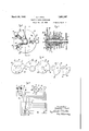
- Fig. 1 is a perspective view of a circuit controller involvwing the features of the invention.
- the mechanism is shown mounted in a box container, the door of which has been removed.
- the mechanism, -which is mounted on a hinged frame is shown swung outward, showing the back of the frame, upon which are mounted the motor, the circuit closing contacts, the gear mechanism and the circuit controlling cams.
- Fig. 2 shows the mechanism with the front part of the frame removed showingthe motor, the gears, the cams, and the circuit closing contacts;
- the-mechanism 59 is shown iii-front elevatiom
- Fig. 3 shows the portion of the .mechanism which comprises the contact operating arm and the controlling cams.
- the controlling arm is shown in one position and the circuit closing contacts are shown in the corresponding posi-. tion.
- Fig. i' is a similar view of the same portion of the apparatus showing the arm in a difi'erent position.
- Figs. 5 and 6 are similar views of the same portion of the apparatus showing the arm in still diiferent positions.
- Fig. 7 is atop view of the circuit closing contacts.
- FIG. 8 shows in elevation the dials and levers or arms in the front of the box through the mediumof which the cams of the device are properly set for the timing desired.
- Fig. 9 is a side view in section of the device taken on line 99, Fig. 8. .
- Fig. 10 shows the cams of Fig. 9 in so-called exploded View and in elevation. In this figure the cams are represented in one of a number of relative posit-ions along a common axis in which they may be adjusted.
- Fig. 11 is a schematic diagram showing the circuits controlled by the device-and a set of signals for a street intersection. In this'figure the circuit over which the operating motor is energized is also shown.
- the motor for driving the device comprises a disk armature 2 and a pair of coils 3 and 4.
- the motor is provided with suitable shading coils which may be adjusted by lever arm 4. for varying the speed of the motor.
- the motor, together with the rest of the mechanism is mounted on a suitable frame having a front plate 5, a rear plate 6, and a number of posts 7, 8, 9, 10 and 11, aswell as a cross bar frame element 12.
- Fig. 2 shows the relation of the gears that are interposed between the motor and the cam mechanism driven-thereby.
- the motor shaft 13 carries a pinion 14 which meshes with gear 15.
- This latter is I mounted on the shaft 16 which carries a pinion 15 which engages'with gear 17 mountas ed on shaft 18 with pinion 19.
- Pinion 19 in turn engages the gear 20 which gear, as shown in Fig. 9, is mounted on a collar 21.
- a cam 22 On the same collar Fig. 9 there is mounted a cam 22. Within the collar 21 there a tubular bearthe ing 23, to which the collar 21 is secured.
- This tube passes through the bearing 24 in the front part of the frame, which tube terminates in a dial 25,
- a second cam 26 which is secured to the collar 27, which collar is in turn secured to the tube 28 located within the tube'23.
- This dog 39 normally engages the teeth 40 on the periphery of the segment 36 due to the tension of coiled springi42.
- another index arm or lever 43 provided with a dog 45 similar to dogs 31 and 39 which normally is held in engagement with the teeth 44 on the peripheral section of the dial 25 by means of the coiled spring 46'.
- the dial segment'36 and the arm 43 are connected by a coiled spring 46, one end of which is secured to the segment and the other ,end of which is secured to the arm 43 tending, normally to draw the segment 36 against the arm 43.
- the object of this spring is to en able the arm 38 to be set or adjusted at any instant regardless of the position of the cams which, at intervals during a cycle of operation lock the segment 36 against counterclockwise rotation. However, at any other time the spring 46 will draw the segment into the newposition determined by the arm 43.
- cams 22, 26, 32, 34 and 51 are indicated in. Fig. 10.
- the relation of these cams to the arm 52 is indicated in Figs. 2 through 7.
- the arm 52 is under the control of the arm 53, both of which arms are pivoted in'common about the pin 54, which is secured tothe frame 5 (see Fig. 1).
- the arm 52 is provided with a spring 55 diagrammatically represented in Fig. 3 and also shown in Fig. 1, which spring tends to rotate the arm 52 in a clockwise direction, Fig. 3.
- the arm 53 in turn is provided with a spring 56 diagrammatically represented in Fig.
- the arm' 53,Fig. 3 is provided with a tail piece 53? which is bent at, right arm and extends parallel to the axis of shaft. 37-. This tail piece is mounted in operative relation to the cams 32, 34, and 51.
- the arm 52 is provided on its end with a 'rod 62'of insulating material.
- the contact springs 63,64 are controlled. These contact springs are also shown in Fig. 11.
- the contact springs 63 and 64 respectively engagecontacts 67 and 68, which latter are electrically connected together.
- the contact spring 65 similarly en- 5 gages a contact 69.
- 64 and 65 are provided with suitable indentations 71, 72, and 73.
- the arm 62 oscillates beneath the springs 63, 64 and 65 and when the arm 62' finds a position in juxtaposition with either one of the said indentations the corresponding spring is allowed to fall into engagement with its corresponding contact, as indicated in Fig. 11, thereby permitting the circuit to be closed between this spring -5 and its corresponding contact.
- the arms 52 and 53 and the cams of Fig. 1 are so related that'when the tail piece 53 is in engagement with the rim 57 of the cam 22, or with the rim .56 of the cam 26, the
- e arm 53 is raised its maximum distance as shown in Figs. 5 and 6 and therefore the tail piece 61 is removed the maximum distance from arm 52, allowing the latter to make a complete forward stroke to the right.
- the second in Fig. 5 and the final position is shown'in F ig. 6.
- the tail piece 52' of arm 52 engages respectively the following cam surfaces (Fig. 10) 60 (or 59 and 60), 82" and 83. This all takes place while the tailpiece 53 of the arm 53 is riding on the surface 57 of cam 22 and before the element 53' clears the point or the point 7 6 of (3211 11 26, depending upon the adjustment of cam 26. As soon as the tail piece 53' clears the point 76 it falls on the surface 77 of cam 22, as indicated in Fig.3, at which time the arm 53 carries the arm 52 back with it one step.
- cam 22 to surface 79 thereof, Fig. 10 initiates the green signal, while the surface 60 of cam 32 determines the earliest time of cutoff of the green signal;
- cam 22 to surface 79 thereof, Fig. 10 initiates the green signal, while the surface 60 of cam 32 determines the earliest time of cutoff of the green signal;
- 59 may be used to delay the time of this cutoff.
- cam 51 may be used to regulate the length of this amber interval.
- the drop from point 82 of cam 51 on to surface 83 of cam 32 initiates the red signal while the drop from points 75 or '76 of cams 22 or 26 on to surface 77 cuts 06' the red and initiates the amber signal during the interval between the red and green signals and so on.
- the current for operating the motor and signals may be supplied over theline conductors 91, 92 the current reaching the motor by Way of conductors 85 and 86.
- the current reaches the contacts 67, 68 and 69 by way of the conductors 87 and 88, returning to the other side of the line by way of the common return conductor 89.
- the cams, Fig. 10 are rotated and the contact springs 63, 64 and 65 are in turnoperated in agiven cycle of operation for correspondingly operating the signals R, A, G, Fig. 11.
- the signals may be operated so as to appear on the main street R-AG-A-R-A etc. or they may be operated in the following order R-A G R etc. or in the following order RGA-R-G.AE depending upon the adjustment of the cams 26, 34 and 51. It will be understood that if the cam 51 completely overlaps the cam 34 there will be no amber signal between the green and red, that is between G and R. On the other hand if the cam 26 completely overlaps the surface77 on the cam 22 there will be no amber between a the red and the green, that is between R installed at one intersection there are four.
- the controlling arm 52 assumes four difierent positions. However, it is possible to increase the number of positions that the arm assumes as for example by notching the cams 26 and 51 along their respective cam surfaces 56' and 82' in the same manner that the cam 22 is notched between'the surfaces 57 and 77. In that case the arm 52'would have two additional intermediate positions, one between the amber and the red, that is between the cam surfaces 82 and 83. and the other between the red and the amber, that is between surfaces 56 and 77.
- the device shown in Fig.- 1 is provided with a flasher, which may be used when the other signals are thrown oil.
- the flasher will serve as a warning in case the other signals are thrown off or in case they go ofi accidentally.
- Thefia'sher comprises the spring 49 andcontact 50 connected in series with which is thefi'ashing lamp 90 as indicated in Fig. 11. It will be seen” that the spring 49 is under the control of the arm 48, which isoperated to oscillate by means ofthe gear wheel'47 mounted on the shaft 37 as alreadyexplained.
- X is a suitable switch for open- I ing and closing the circuits to contacts 67, 68
- Y is a suitable switch controlling the flasher contact 50.
- cams 22 and 32 may be considered as being main cams, and cams 26, 34 and 51 may be considered as auxiliary cams, cam 26 being adjustable relatively to cam 22. and cams 34. and 51 being adjustable relatively to cam 32.
- a'circuit controller in combination, a plurality of switches, an arm, cam means for operating said arm, and means whereby when the arm is operated said switches may be operated in turn, each independently of the other, said cam means comprising a pair of adjustable cam elements, a ,pair of adjusting elements one for and connected with each of said cam elements, each of said cam adj ust able elements being mounted on a different shaft together with its adjusting element, said shafts all having a common axis ofrotationfisa d adjusting arms being all grouped together at one'end of said axis wherebysaid cam elements may be adjustedfrom one point to vary the operation of said switches.
- said cam means comprising a pair of adjustable cam elements, a pair of adjusting elements one for and connected with each of said cam elements, said adjusting elements being located in front of a plane and said cam means being located behind said plane whereby said cams may be adjusted from. a point in front said plane to vary the operation of said switches, index means for each adjusting arm for indicating the degree of adjust- -ment, and means for latching said arms to-.
- a driving element in combination, a driving element, a pair of'main. cams secured to said driving element, an auxiliary cam located in operative relation to one of said main cams, a second auxiliary cam located in operative relation to the other one of said main cams, a third auxiliary cam mounted in operative relation to the second auxiliary cam, the auxiliary cams being mounted to be adjusted independently, and index arms, one for each auxiliary cam, each arm being connected with its corresponding auxiliary cam, said arms being all located on one side of a plane and said cams being located on the other side thereof whereby any adjustment of said cams behind the plane may be performed from in front thereof.
- a circuit controller in combination and having a common axis of rotation, a driving element, a shaft therefore, a pair of main cams secured to said driving element, an auxiliary cam located in operative relation to one of said main cams, a shaft for the auxiliary cam, a second auxiliary cam located in operative relation to the other one of said main cams, a shaft for the second auxiliary cam, a third auxiliary cam mounted in operative relation to the second auxiliary cam and a shaft for the third auxiliary cam, the shafts of the auxiliary cams being independently rotatable whereby the cams may be adjusted independently, and an index arm on the end, of each shaft for indicating the adjustment of each auxiliary cam, said index arms being located on one side of a plane and the said cams being located on the rear thereof whereby said cams may be adjusted from a point in front of said plane.
- a circuit controller in combination, an arm, a set of three switches, cam means for moving said arm into three different positions whereby the three switches may be operated one at a time each independently of the other, said cam means comprising three cam elements, each being adjustable independently of the other and withrespect to said arm whereby the interval that the arm remains in each position may be varied, an index arm for each adjustable cam element, all
- a circuit controller in combination, a wall, a shaft which projects thorough said wall, a plurality of cams carried by said shaft at the rear of the-wall, means for adjusting said cams relatively to each other, means for adjusting the effective lengths of said cams, and means located at the rout of said wall for operating said adjusting means and fixing them in adjusted positions.
- a circuit controller in combination, a wall, a shaft which projects thorough said wall, a plurality of main cams carried by said shaft at the rear of the wall, a plurality of auxiliary cams associated with the main cams for adjusting the effective lengths of the main cams, shafts for said auxiliary cams which extend forward to the front of said wall, and means on the auxiliary cam shafts in front of said wall for turnin said shafts to adjust the auxiliary cams and fix them in adjusted positions.
- a circuit controller in combination, a wall, a shaft which projects through said wall, a plurality of main cams carried by said shaft at the rear of the wall, a plurality of auxiliary cams associated with the main cams for adjusting the effective lengths of the main cams, concentric shafts for said auxiliary cams which terminate in front of said walls, a dial carried by the first named shaft in front of said wall, and adjusting arms carried by said concentric shafts and adapted tobe fastened to said dial for locking the auxiliary cams in adjusted positions.
- a circuit controller in combination, a driving element, a plurality of main cams secured to said driving element, auxiliary cams located in operative relation to the main cams, said auxiliary cams being mounted to be adjusted independently, and index arms, one for each auxiliary cam, each arm being connected with its corresponding auxiliary cam, said arms being all located on one side of a plane and said cams being located on the other side thereof, whereby any adjustment of said cams behind the plane may Q
Landscapes
- Physics & Mathematics (AREA)
- General Physics & Mathematics (AREA)
- Toys (AREA)
Description
March 29, 1932. c. l. HALL TRAFFIC SIGNAL CONTROLLER Filed Feb. 12, 1929- 2 Sheets-Sheet. 1
b H is Attor-ng;
mum
5 1 W 9" Fl WI @5. a
Maul-1 29, 1932; C. I. HALL 1,351,24?
TRAFF'IC SIGNAL CONTROLLER File d Feb. 12, 1929 2 Shts-Sheet 2 Inventor Chester- 1. Hal l His Attqrngy Patented Mar. 29, 1932 umrsn STATES PATENT orr ca CHESTER I. HALL, .PHILADELPHIA, JENNSYIJTAINIA, 'ASSIGNOR TO GENERAL ELEC- TRIO COMPANY, A GORPORATION OF NEW YORK TRAFFIC SIGNAL CONTROLLER Application filed February 12, 1829. Serial No. 339,349.
My invention relates to circuit controllers. More particularly it relates to circuit controllers of the type especially adapted for use in connection with the operation of traihc 5 signals.
In regulating trafic along a thoroughfare across which extend other avenues of trafic or cross roads, it is desirable that the time interval during which the traffic is allowed 1a to proceed along. the main thoroughfare and along the crossroads be changed from time to time. In connection with such traffic Sig-- nals it is not only customary to have stop signals and go signals, but it is also common to have change signals.
It is an object of my invention to provide a circuit controller the mechanism of which is adapted to be enclosed in a suitable container, which mechanism comprises timin means for operating go, stop, an
change signals for both the main highway and the cross roads and by means of which the ratio of the'go and stop signals may be varied, as well as the length of the 2 change signal" in either direction. It is also an object of the invention to provide suitable dials in order that a trafiic oflicer I may readily and effectively change the timing of all of said signals to suit the trafiic at conditions at any particular time without havlng to open up the casing.
The invention will be more readily understood from the following specification and claims, reference being had to the accom- 85 panying drawings in-which Fig. 1 is a perspective view of a circuit controller involvwing the features of the invention. In this figure the mechanism is shown mounted in a box container, the door of which has been removed. In this figure the mechanism, -which is mounted on a hinged frame, is shown swung outward, showing the back of the frame, upon which are mounted the motor, the circuit closing contacts, the gear mechanism and the circuit controlling cams.
Fig. 2 shows the mechanism with the front part of the frame removed showingthe motor, the gears, the cams, and the circuit closing contacts; In thisfigu're the-mechanism 59 is shown iii-front elevatiom Fig. 3 shows the portion of the .mechanism which comprises the contact operating arm and the controlling cams. The controlling armis shown in one position and the circuit closing contacts are shown in the corresponding posi-. tion. Fig. i'is a similar view of the same portion of the apparatus showing the arm in a difi'erent position. Figs. 5 and 6 are similar views of the same portion of the apparatus showing the arm in still diiferent positions. Fig. 7 is atop view of the circuit closing contacts. Fig. 8 shows in elevation the dials and levers or arms in the front of the box through the mediumof which the cams of the device are properly set for the timing desired. Fig. 9 is a side view in section of the device taken on line 99, Fig. 8. .Fig. 10 shows the cams of Fig. 9 in so-called exploded View and in elevation. In this figure the cams are represented in one of a number of relative posit-ions along a common axis in which they may be adjusted. Fig. 11 is a schematic diagram showing the circuits controlled by the device-and a set of signals for a street intersection. In this'figure the circuit over which the operating motor is energized is also shown.
Referring to Fig. 1 of the drawings, the motor for driving the device comprises a disk armature 2 and a pair of coils 3 and 4. The motor is provided with suitable shading coils which may be adjusted by lever arm 4. for varying the speed of the motor. The motor, together with the rest of the mechanism is mounted on a suitable frame having a front plate 5, a rear plate 6, and a number of posts 7, 8, 9, 10 and 11, aswell as a cross bar frame element 12.
Fig. 2 shows the relation of the gears that are interposed between the motor and the cam mechanism driven-thereby. It will be seen that the motor shaft 13 carries a pinion 14 which meshes with gear 15. This latter is I mounted on the shaft 16 which carries a pinion 15 which engages'with gear 17 mountas ed on shaft 18 with pinion 19. Pinion 19 in turn engages the gear 20 which gear, as shown in Fig. 9, is mounted on a collar 21.' On the same collar Fig. 9 there is mounted a cam 22. Within the collar 21 there a tubular bearthe ing 23, to which the collar 21 is secured.
This tube passes through the bearing 24 in the front part of the frame, which tube terminates in a dial 25, Next to the cam 22 there is a second cam 26 which is secured to the collar 27, which collar is in turn secured to the tube 28 located within the tube'23.
" 25 and which is provided, for convenience,
with a knob as shown. Therefore, by unlatching the arm 29 from the teeth and rotating it 'the cam 26 may be adjusted with respect to the cam 22.
Behind the cam 26 there is a third cam 32, which is loosely mounted on a hollow tube element 33. This cam is secured to the cam 22 by means of a bolt 32'. Obviously, therefore, the two cams 22 and 32 are rlgidly connected together. Consequently, when the gear 20 is rotated both cams 22 and 32 must rotate withit. Just beyond the cam 32 there is a fourth cam 34 which is secured to the collar 35, which collar is in turn secured to the tube 33. This tube terminates in a dial segment element 36. Within the tube 33 there is a shaft 37 to which there is secured an in dex arm or lever 38. This lever is provided a with a dog 39 similar to dog 31. This dog 39 normally engages the teeth 40 on the periphery of the segment 36 due to the tension of coiled springi42. Between the segment 36 and the lever 29 there is loosely mounted another index arm or lever 43 provided with a dog 45 similar to dogs 31 and 39 which normally is held in engagement with the teeth 44 on the peripheral section of the dial 25 by means of the coiled spring 46'. The dial segment'36 and the arm 43 are connected by a coiled spring 46, one end of which is secured to the segment and the other ,end of which is secured to the arm 43 tending, normally to draw the segment 36 against the arm 43. The object of this spring is to en able the arm 38 to be set or adjusted at any instant regardless of the position of the cams which, at intervals during a cycle of operation lock the segment 36 against counterclockwise rotation. However, at any other time the spring 46 will draw the segment into the newposition determined by the arm 43.
It will be seen that the shaft 37. Fig. 9,
passes through the frame member 12 at the right and-has secured to its'inner terminal a gear 47 which serves to'controla lever 48 (see Fig'i 1)'which latter-{in turn, controls the contact spring 49 associated with the circuit contact 50 (see Fig. 11) Whenthis gear is rotated the arm oscillates and causes the contacts 49 and 50 to make and break regularly for controlling a flash signal when the rows as viewed in Fig. 10. It will be understoodlthat'the maximum radii R of cams 22, 26, 32 and 34 are all the shaft at a point'between the cam 34 andthe frame support 12, Fig. 9.
With the mechanism described when the .gear 20 is rotated by the motor the whole mechanism shown in Fig. 9 rotates about the bearing 24 inasmuch as all of the elements are interlocked by means of the levers 29, 38 and 43, and their dogs. However, the cam 26 is adjustable with respect to the cam 22 through the medium of the lever .29. Similarly the cam 51 is adjustable with respect to both cams 34 and 32 through the medium of the lever 38. Furthermore, both cams 34 and 51 are adjustable simultaneously with respect to the cam 32 through the medium of the lever '43, inasmuch as the'lever 38 locks cams 34 and 51 together. A
One relation of cams 22, 26, 32, 34 and 51 with respect to each other along the axis of the shaft 37 is indicated in. Fig. 10. The relation of these cams to the arm 52 is indicated in Figs. 2 through 7. It will be seen that the arm 52 is under the control of the arm 53, both of which arms are pivoted in'common about the pin 54, which is secured tothe frame 5 (see Fig. 1). Referring to the same figures, 2 through'7, the arm 52 is provided with a spring 55 diagrammatically represented in Fig. 3 and also shown in Fig. 1, which spring tends to rotate the arm 52 in a clockwise direction, Fig. 3. The arm 53 in turn is provided with a spring 56 diagrammatically represented in Fig. 3,which tends to rotate the arm 53 in a counter-clockwise direction. This spring 56 is strcngerv than spring 55. Furthermore, the arm' 53,Fig. 3, is provided with a tail piece 53? which is bent at, right arm and extends parallel to the axis of shaft. 37-. This tail piece is mounted in operative relation to the cams 32, 34, and 51.
When the current. is turned on, the motor armature disk 2 rotates in the direction of the arrow. Figs. 1 and 2, which means, of course, that the gear 20 rotates in the opposite ,di-
rection and therefore that the dial 25- rotates in the same direction with gear 20, that is, in a clockwise direction, as viewed in Fig. 8. The cams 22, 26, 32, 34 and 51, therefore, rotate in the direction indicated by the arsame in'length; that the radius R of the cam 51 is shorter than the radii R and is longer thanthe radius R of cam 32, or than radius R of cam 22, radius B being longer than R angles tothe face of the arm and engages the The two cams 22 and 26 are mounted side'by side andtherim portion 56' ofcam 26 forms M Fig. 4, green with contacts 64 Therefore, the drop from surface 77 a continuation or extension of the rim portion 57 of the cam 22 with respect to the tail 5 face of cam 32. I
As indicated in Figs. 3 through 7, the arm 52 is provided on its end with a 'rod 62'of insulating material. Through the medium of this arm the contact springs 63,64, and are controlled. These contact springs are also shown in Fig. 11. The contact springs 63 and 64 respectively engagecontacts 67 and 68, Which latter are electrically connected together. The contact spring 65 similarly en- 5 gages a contact 69. The contact springs 63,
64 and 65 are provided with suitable indentations 71, 72, and 73. The arm 62 oscillates beneath the springs 63, 64 and 65 and when the arm 62' finds a position in juxtaposition with either one of the said indentations the corresponding spring is allowed to fall into engagement with its corresponding contact, as indicated in Fig. 11, thereby permitting the circuit to be closed between this spring -5 and its corresponding contact.
The arms 52 and 53 and the cams of Fig. 1 are so related that'when the tail piece 53 is in engagement with the rim 57 of the cam 22, or with the rim .56 of the cam 26, the
e arm 53 is raised its maximum distance as shown in Figs. 5 and 6 and therefore the tail piece 61 is removed the maximum distance from arm 52, allowing the latter to make a complete forward stroke to the right. The
5 first position of the stroke is shown in Fig. 4,
the second in Fig. 5 and the final position is shown'in F ig. 6. In these three positions the tail piece 52' of arm 52 engages respectively the following cam surfaces (Fig. 10) 60 (or 59 and 60), 82" and 83. This all takes place while the tailpiece 53 of the arm 53 is riding on the surface 57 of cam 22 and before the element 53' clears the point or the point 7 6 of (3211 11 26, depending upon the adjustment of cam 26. As soon as the tail piece 53' clears the point 76 it falls on the surface 77 of cam 22, as indicated in Fig.3, at which time the arm 53 carries the arm 52 back with it one step. Finally, when the tail piece 53 clears the point 78 it falls on the surface 79,-at xwhich time the arm 53 again advances the arm 52 to the position shown in Fig. 4. Arm 52, therefore, carries circuit controlling arm 62 back and forth, thereby controlling the signal circuits indicated in Fig. 11 in the proper sequence as indicated in Figs. 4, 5,
i 6 and 3. The signal indications corresponding to the .positions of the arm 52 in Figs. 4, 5, 6 and 3 respectively are as follows:
Fig. 5, amber with contacts 65 and 69 closed; Fig. 6, and Fig. 3, closed again.
.in the following order and 68 closed red-with contacts 71 and 67 closed, amber-with contacts 65 and 69,
59 may be used to delay the time of this cutoff.
The drop from points 80 or 81 of cams 32 or 34 on to cam surface 82 of cam 51 initiates the amber signal for the interval between,
the green and the red signals, and cam 51 may be used to regulate the length of this amber interval. The drop from point 82 of cam 51 on to surface 83 of cam 32 initiates the red signal while the drop from points 75 or '76 of cams 22 or 26 on to surface 77 cuts 06' the red and initiates the amber signal during the interval between the red and green signals and so on.
Referring to Fig. 11, the current for operating the motor and signals may be supplied over theline conductors 91, 92 the current reaching the motor by Way of conductors 85 and 86. The current reaches the contacts 67, 68 and 69 by way of the conductors 87 and 88, returning to the other side of the line by way of the common return conductor 89.
Therefore by means of the motor, the cams, Fig. 10, are rotated and the contact springs 63, 64 and 65 are in turnoperated in agiven cycle of operation for correspondingly operating the signals R, A, G, Fig. 11. F or example, the signals may be operated so as to appear on the main street R-AG-A-R-A etc. or they may be operated in the following order R-A G R etc. or in the following order RGA-R-G.AE depending upon the adjustment of the cams 26, 34 and 51. It will be understood that if the cam 51 completely overlaps the cam 34 there will be no amber signal between the green and red, that is between G and R. On the other hand if the cam 26 completely overlaps the surface77 on the cam 22 there will be no amber between a the red and the green, that is between R installed at one intersection there are four.
groups of signals, one group facing one way on the main thoroughfare and another group facing in the opposite direction, each group corresponding to the group R, G, A. Fig. 11. A third direction on a cross road and a fourth group facing in the opposite direction on the cross road. in which case there would be four red signals, R R R and R andfour green signals G G signals A A A and A Considering the R and G and 3 and G as being assigned to the main highway and R R and G Gr as being assigned to the cross road, the signals R R G and G would be put on'o'ne circuit, the signals G G R and R on another cirgroup may be placed facing in one- G and G and four amber on a .single circuit, or they may be divided into two circuits with the signals A and A on one circuit assigned to the main highway, and A; and A on a different circuit, assigned to'the cross road. However, if the amber signals are to be built into two circuits, as indicated by the dotted lines, Fig. 11, two springs similar to spring 65 must be supplied. When all the amber signals are to be controlled over a single circuit only three springs are used, as indicated in Fig. 7, in which case the indentation 73 of spring 65 is broad enough to cover two positions of roller 62 for amber. When the amber signal circuits are split four springs are used and another spring is supplied next to 65, Fig. 7, the new spring and spring 75 each having an indentation broad enough to'cover only one position of The same cam arrangement is roller 62. used in both cases.
It will be seen that with the arrangement of cams shown in Fig. 10 the controlling arm 52 assumes four difierent positions. However, it is possible to increase the number of positions that the arm assumes as for example by notching the cams 26 and 51 along their respective cam surfaces 56' and 82' in the same manner that the cam 22 is notched between'the surfaces 57 and 77. In that case the arm 52'would have two additional intermediate positions, one between the amber and the red, that is between the cam surfaces 82 and 83. and the other between the red and the amber, that is between surfaces 56 and 77.
. Obviously with this arrangement-it would be possible to have signals for the main highway as follows: R, RA, A, G, A, RA- R. In other words, the amber and the red would overlap in both instances, that is in passing from amber to red and in passing from red 'to amber.. Similarly, it would be possible to notch the cam. 34, thereby creating an additionalstep between the cam surfaces 59 and 82, thus making it possible to overlap the green and the amber in passing from green to amber. By notching the surface 77 an;
'additional step would be given to thecam so as to produce an overlap between the amber and the green in passing from-amberto green. Obviously, the same variations may be produced with respect to the signals-as viewed along the cross streets. v
The device shown in Fig.- 1 is provided with a flasher, which may be used when the other signals are thrown oil. Inasmuch as the 0th er signals are not on the same circuit with the flasher,=the flasher will serve as a warning in case the other signals are thrown off or in case they go ofi accidentally. Thefia'sher comprises the spring 49 andcontact 50 connected in series with which is thefi'ashing lamp 90 as indicated in Fig. 11. It will be seen" that the spring 49 is under the control of the arm 48, which isoperated to oscillate by means ofthe gear wheel'47 mounted on the shaft 37 as alreadyexplained.
In Fig. 11, X is a suitable switch for open- I ing and closing the circuits to contacts 67, 68
and 69, and Y is a suitable switch controlling the flasher contact 50.
In connection with the construction, cams 22 and 32 may be considered as being main cams, and cams 26, 34 and 51 may be considered as auxiliary cams, cam 26 being adjustable relatively to cam 22. and cams 34. and 51 being adjustable relatively to cam 32.
It will be understood-that while I have elected to illustrate and describe my invention in connection with the specific apparatus that I have illustrated, I do not wish to be so limited in as much as my invention contemplates variations and modifications withof said -cam elements, said adjusting elements .being located in front of a plane and said cam means being located behind sald .plane whereby sa d, camsmay be adjusted from a point in front said plane to vary the operation of said sw tches.
2. In a'circuit controller, in combination, a plurality of switches, an arm, cam means for operating said arm, and means whereby when the arm is operated said switches may be operated in turn, each independently of the other, said cam means comprising a pair of adjustable cam elements, a ,pair of adjusting elements one for and connected with each of said cam elements, each of said cam adj ust able elements being mounted on a different shaft together with its adjusting element, said shafts all having a common axis ofrotationfisa d adjusting arms being all grouped together at one'end of said axis wherebysaid cam elements may be adjustedfrom one point to vary the operation of said switches.
' *3. In a circuit controller, in combination, a
plurality of switches, an arm, cam means for operating said arm. and means whereby when thearm s operated said switches may be operated in turn, eachindependently of the other, said cam means comprising a pair of adjustable cam elements, a pair of adjusting elements one for and connected with each of said cam elements, said adjusting elements being located in front of a plane and said cam means being located behind said plane whereby said cams may be adjusted from. a point in front said plane to vary the operation of said switches, index means for each adjusting arm for indicating the degree of adjust- -ment, and means for latching said arms to-.
gether whereby the said cam elements may be moved in unison after adjustment.
4. In a circuit controller, in combination, a driving element,a pair of'main. cams secured to said driving element, an auxiliary cam located in operative relation to one of said main cams, a second auxiliary cam located in operative relation to the other one of said main cams, a third auxiliary cam mounted in operative relation to the second auxiliary cam, the auxiliary cams being mounted to be adjusted independently, and index arms, one for each auxiliary cam, each arm being connected with its corresponding auxiliary cam, said arms being all located on one side of a plane and said cams being located on the other side thereof whereby any adjustment of said cams behind the plane may be performed from in front thereof.
5. In a circuit controller, in combination and having a common axis of rotation, a driving element, a shaft therefore, a pair of main cams secured to said driving element, an auxiliary cam located in operative relation to one of said main cams, a shaft for the auxiliary cam, a second auxiliary cam located in operative relation to the other one of said main cams, a shaft for the second auxiliary cam, a third auxiliary cam mounted in operative relation to the second auxiliary cam and a shaft for the third auxiliary cam, the shafts of the auxiliary cams being independently rotatable whereby the cams may be adjusted independently, and an index arm on the end, of each shaft for indicating the adjustment of each auxiliary cam, said index arms being located on one side of a plane and the said cams being located on the rear thereof whereby said cams may be adjusted from a point in front of said plane.
6. In a circuit controller, in combination, an arm, a set of three switches, cam means for moving said arm into three different positions whereby the three switches may be operated one at a time each independently of the other, said cam means comprising three cam elements, each being adjustable independently of the other and withrespect to said arm whereby the interval that the arm remains in each position may be varied, an index arm for each adjustable cam element, all
of said elements of said controller being sesaid adjustable index cured within a frame, arms being all located outside said frame whereby said cams may be adjusted from a point outside the framet 7 In a circuit controller, in combination, a wall, a shaft which projects thorough said wall, a plurality of cams carried by said shaft at the rear of the-wall, means for adjusting said cams relatively to each other, means for adjusting the effective lengths of said cams, and means located at the rout of said wall for operating said adjusting means and fixing them in adjusted positions.
, 8. In a circuit controller, in combination, a wall, a shaft which projects thorough said wall, a plurality of main cams carried by said shaft at the rear of the wall, a plurality of auxiliary cams associated with the main cams for adjusting the effective lengths of the main cams, shafts for said auxiliary cams which extend forward to the front of said wall, and means on the auxiliary cam shafts in front of said wall for turnin said shafts to adjust the auxiliary cams and fix them in adjusted positions.
9. In a circuit controller, in combination, a wall, a shaft which projects through said wall, a plurality of main cams carried by said shaft at the rear of the wall, a plurality of auxiliary cams associated with the main cams for adjusting the effective lengths of the main cams, concentric shafts for said auxiliary cams which terminate in front of said walls, a dial carried by the first named shaft in front of said wall, and adjusting arms carried by said concentric shafts and adapted tobe fastened to said dial for locking the auxiliary cams in adjusted positions.
10. In a circuit controller, in combination, a driving element, a plurality of main cams secured to said driving element, auxiliary cams located in operative relation to the main cams, said auxiliary cams being mounted to be adjusted independently, and index arms, one for each auxiliary cam, each arm being connected with its corresponding auxiliary cam, said arms being all located on one side of a plane and said cams being located on the other side thereof, whereby any adjustment of said cams behind the plane may Q
Priority Applications (1)
| Application Number | Priority Date | Filing Date | Title |
|---|---|---|---|
| US339349A US1851247A (en) | 1929-02-12 | 1929-02-12 | Traffic signal controller |
Applications Claiming Priority (1)
| Application Number | Priority Date | Filing Date | Title |
|---|---|---|---|
| US339349A US1851247A (en) | 1929-02-12 | 1929-02-12 | Traffic signal controller |
Publications (1)
| Publication Number | Publication Date |
|---|---|
| US1851247A true US1851247A (en) | 1932-03-29 |
Family
ID=23328607
Family Applications (1)
| Application Number | Title | Priority Date | Filing Date |
|---|---|---|---|
| US339349A Expired - Lifetime US1851247A (en) | 1929-02-12 | 1929-02-12 | Traffic signal controller |
Country Status (1)
| Country | Link |
|---|---|
| US (1) | US1851247A (en) |
Cited By (10)
| Publication number | Priority date | Publication date | Assignee | Title |
|---|---|---|---|---|
| US2429084A (en) * | 1946-03-01 | 1947-10-14 | Gen Electric | Adjustable cam |
| US2454362A (en) * | 1942-04-21 | 1948-11-23 | Westinghouse Electric Corp | Autoamtic molding press |
| US2469761A (en) * | 1944-08-21 | 1949-05-10 | Bodmer Ernest | Cam controlled pulse transmitter |
| US2504002A (en) * | 1943-09-27 | 1950-04-11 | Honeywell Regulator Co | Stoker timer |
| US2508313A (en) * | 1943-03-03 | 1950-05-16 | Hartford Nat Bank & Trust Co | Mechanical movement |
| US2516178A (en) * | 1950-07-25 | Magneto breaker point assembly | ||
| US2542995A (en) * | 1946-09-27 | 1951-02-27 | Bendix Aviat Corp | Predetermined quantity summing apparatus |
| US2797400A (en) * | 1954-06-01 | 1957-06-25 | Mary P Schumacher | Traffic light control mechanism |
| US2817724A (en) * | 1955-11-07 | 1957-12-24 | William A Skidgel | Circuit controller in traffic control system |
| US2920152A (en) * | 1957-09-06 | 1960-01-05 | Harry C Werner | Time limit switch |
-
1929
- 1929-02-12 US US339349A patent/US1851247A/en not_active Expired - Lifetime
Cited By (10)
| Publication number | Priority date | Publication date | Assignee | Title |
|---|---|---|---|---|
| US2516178A (en) * | 1950-07-25 | Magneto breaker point assembly | ||
| US2454362A (en) * | 1942-04-21 | 1948-11-23 | Westinghouse Electric Corp | Autoamtic molding press |
| US2508313A (en) * | 1943-03-03 | 1950-05-16 | Hartford Nat Bank & Trust Co | Mechanical movement |
| US2504002A (en) * | 1943-09-27 | 1950-04-11 | Honeywell Regulator Co | Stoker timer |
| US2469761A (en) * | 1944-08-21 | 1949-05-10 | Bodmer Ernest | Cam controlled pulse transmitter |
| US2429084A (en) * | 1946-03-01 | 1947-10-14 | Gen Electric | Adjustable cam |
| US2542995A (en) * | 1946-09-27 | 1951-02-27 | Bendix Aviat Corp | Predetermined quantity summing apparatus |
| US2797400A (en) * | 1954-06-01 | 1957-06-25 | Mary P Schumacher | Traffic light control mechanism |
| US2817724A (en) * | 1955-11-07 | 1957-12-24 | William A Skidgel | Circuit controller in traffic control system |
| US2920152A (en) * | 1957-09-06 | 1960-01-05 | Harry C Werner | Time limit switch |
Similar Documents
| Publication | Publication Date | Title |
|---|---|---|
| US1851247A (en) | Traffic signal controller | |
| US2090619A (en) | Traffic control system | |
| US1856832A (en) | Circuit controller | |
| US1851246A (en) | Circuit controller | |
| US2194310A (en) | Signaling system and apparatus | |
| US1874513A (en) | Traffic signal controller | |
| US2555994A (en) | Traffic signal controller with pedestrian actuation | |
| US2126431A (en) | Automatically operated traffic control system | |
| US1701398A (en) | Periodic switching mechanism | |
| US2624793A (en) | Traffic signaling system and apparatus | |
| US2451457A (en) | Traffic signal control system | |
| US3133264A (en) | Multiple program traffic control systems | |
| US1863931A (en) | Selective control mechanism for radio sets | |
| US2053110A (en) | Signaling system and apparatus | |
| US1973563A (en) | Highway traffic signal system | |
| US1893365A (en) | Circuit controller | |
| US1969293A (en) | Automatic timing switch for traffic signals | |
| US1745975A (en) | bissell | |
| US1926833A (en) | Electrical flasher | |
| US2050039A (en) | Signaling system and circuit controller for use therein | |
| US2199573A (en) | Traffic signal | |
| US1640170A (en) | Street-traffic-signal device | |
| US1931350A (en) | Traffic control system | |
| US1851508A (en) | Circuit controller | |
| US1908077A (en) | Traffic control apparatus |