US1856831A - Front wheel drive system for motor vehicles - Google Patents
Front wheel drive system for motor vehicles Download PDFInfo
- Publication number
- US1856831A US1856831A US415705A US41570529A US1856831A US 1856831 A US1856831 A US 1856831A US 415705 A US415705 A US 415705A US 41570529 A US41570529 A US 41570529A US 1856831 A US1856831 A US 1856831A
- Authority
- US
- United States
- Prior art keywords
- gear
- front wheel
- shaft
- motor vehicles
- wheel
- Prior art date
- Legal status (The legal status is an assumption and is not a legal conclusion. Google has not performed a legal analysis and makes no representation as to the accuracy of the status listed.)
- Expired - Lifetime
Links
- 230000005540 biological transmission Effects 0.000 description 2
- 241000053208 Porcellio laevis Species 0.000 description 1
- 235000015115 caffè latte Nutrition 0.000 description 1
- 239000000428 dust Substances 0.000 description 1
- 239000000314 lubricant Substances 0.000 description 1
Images


Classifications
-
- B—PERFORMING OPERATIONS; TRANSPORTING
- B60—VEHICLES IN GENERAL
- B60K—ARRANGEMENT OR MOUNTING OF PROPULSION UNITS OR OF TRANSMISSIONS IN VEHICLES; ARRANGEMENT OR MOUNTING OF PLURAL DIVERSE PRIME-MOVERS IN VEHICLES; AUXILIARY DRIVES FOR VEHICLES; INSTRUMENTATION OR DASHBOARDS FOR VEHICLES; ARRANGEMENTS IN CONNECTION WITH COOLING, AIR INTAKE, GAS EXHAUST OR FUEL SUPPLY OF PROPULSION UNITS IN VEHICLES
- B60K17/00—Arrangement or mounting of transmissions in vehicles
- B60K17/30—Arrangement or mounting of transmissions in vehicles the ultimate propulsive elements, e.g. ground wheels, being steerable
- B60K17/306—Arrangement or mounting of transmissions in vehicles the ultimate propulsive elements, e.g. ground wheels, being steerable with a universal joint in the axis of the steering knuckle
Definitions
- This invention relates to front wheel drive systems for motor vehicles and more particularly to the type of drive in which each front wheel is driven by means of a longitudinal shaft running alongside the main frame from the ends of a transverse shaft operated from a variable speed gear driven by the motor.
- the present invention has particular reference to the manner in which the transverse shaft receives its motion from the variable speed gear, and to the manner in which the drive is transmitted from the longitudinal shafts to the front steering road wheels.
- the invention involves the provision within the ordinary gear box or in a gear box auxiliary thereto of a gear member which takes the final drive at all speeds.
- the transverse shaft is driven from this gear member in any suitable manner as by means of spur or bevel gear and provision may be made whereby the drive between the transverse shaft and said gear member may be disconnected at will.
- the drive from the front end of the longitudinal shaft at each side of the vehicle is taken through bevel or worm gear, mounted either upon the mam frame or upon the front axle and thence through a short universally jointed outwardly directed shaft to spur or skew gear attached to the front wheel hub.
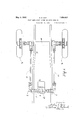
- Figure 1 is a plan View showing the gen- 5 eral arrangement of the front wheel drive system.
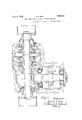
- Figure 2 is a sectional view on a larger scale showing the manner in which the transverse shaft derives its motion from the va- 49 riable speed gear.
- Figure 3 is a sectional plan view of the same.
- Figure 4 shows a sectional front view of a front wheel drive in which the driving gear is supported off the frame of the vehicle.
- Figure 5 is a similar view in which the drive is-supported off the axle.
- a, a represent the longitudinalv side shafts which drive the front wheelsb, b 0, indicates the transverse shaft and cl the gear box.
- the transmission of power from thetransverse shaft to the longitudinal shafts may be by bevel gear 6, 6 ed each end of the former.
- the main shaft (Z of an otherwise orthodox variable speed gear at of the sliding gear type is extended at one end to carry an extra gear wheel 9 which takes the final drive at all speeds. It is from this wheel 9 that the transverse shaft 0 derives its motion, the transmission of the drive taking place through two intermediate shafts, one it of which carries an idle gear wheel '5, Whilst the other shaft 7' carries a gear wheel 70 and also a bevel wheel Z in constant mesh with a bevel wheel m, Figure 3, on the trans- 5 verse shaft 0.
- the front wheel drive may be used as an emergency drive for rear driven vehicles in which case some provision is necessary for throwing the front wheel drive into and out of commission as and when required.
- Figure 2' One way of carrying this into practical effect is shown in Figure 2', where it will be seen that the gear wheel is is slidably mounted on featherson' its shaft into and out of operative driven connection with the idle gear member i on the shaft h.
- the said gear member 70 may carry a grooved extension at adapted toreceive a striking fork 0 adapted for operation by the driver in any suitable manner.
- the whole of the gear is enclosed in a casing which may conveniently form part of the casing of the variable speed gear (Z.
- the transverse shaft may be arranged, as reprefrom the forward ends shafts a,"a to each front as shown 111C ⁇ sented in Figure l,above the gear box in suitable bearings carried by the main frame p and may be divided transversely and the two parts connected together by the differential gear as shown in Figure 3.
- V 2 For thespu'rpose of transmitting the drive of the longitudinal wheel I) the latte'i, igures ⁇ l and 5, is providedwith a'gear'member b which is in constant mesh with a drivingpinion q fixed to the outer end of a shortuniversally jointed transverse shaft 0, the inner end of which carries a bevel wheel 8 in driven relationship with a bevel wheel 25 on the forward end of the adjacent longitudinal shaft a.
- Worm gear may be substituted for the bevel gear 8, t if desired.
- the bevel or worm gear aforesaid is carried by the main frame p the universal joint or joints 1 in the transverse shaft 1* allow both for the deflection of the wheel in steering and also for the rise and fall of the wheels when passing over uneven surfaces.
- the spur or skew gear 6 g at the wheel hub can be enclosed in a dust and oil-tight casing o adapted to contain a supply of lubricant.
- each propelling wheel is driven by means of a longitudinal shaft running alongside the main frame from the ends of a transverse shaft operated fronr a motor driven variable speed gear
- a motor driven variable speed gear the interposition between said transverse shaft and variable speed gear of a disconnectible drive comprising a shaft arranged at right angles to and in constant driving connection with the transverse shaft, a pinion slidably arranged on said right angle shaft and adapted to rotate therewith, and means for moving said pinion into and out of driving connection with said variable speed gear.
- each front wheel is driven by means of a longitudinal shaft running alongside the main frame from the ends of a transverse shaft operated by a motor driven variable speed gear
Landscapes
- Engineering & Computer Science (AREA)
- Chemical & Material Sciences (AREA)
- Combustion & Propulsion (AREA)
- Transportation (AREA)
- Mechanical Engineering (AREA)
- Arrangement And Driving Of Transmission Devices (AREA)
Description
May 3, 1932. s. s. GUY
FRONT WHEEL DRIVE SYSTEM FOR MOTOR VEHICLES Filed Dec. 21; 1929 5 Sheets-Sheet 1 IN VENTOR May 3, 1932. s. s. GUY 1,856,831
FRONT WHEEL DRIVE SYSTEM FOR MOTOR VEHICLES Filed Dec. 21, 1929 5 Sheets-Sheet 2 s. s. GUY 1,856,831
May 3, 1932.-
FRONT WHEEL DRIVE SYSTEM FOR MOTOR VEHICLES 5 Sheets-Sheet 5 Filed Dec. 21, 1929 i i o 0 O & r VVEN May 3, 1932. S. s.- UY 1,856,831
FRONT WHEEL DRIVE SYSTEM FOR MOTOR VEHICLES Filed Dec. 21, 1929 5 Sheets-Sheet 4 Fag:
j N VE N TOP.
wmim
y 3, 1932- s. s. GUY 1,856,831
FRONT WHEEL DRIVE SYSTEM FOR MOTOR VEHICLES Filed Dec. 21, 1929 5 Sheets-Sheet 5 1 v vmroR QZW Patented May 3, 1932 SYDNEY SLATER GUY, 0F WOLVERHAMPTON, ENGLAND FRONT WHEEL DRIVE SYSTEM FOR MOTOR VEHICLES Application filed December 21, 1929, Serial No. 415,705, and in Great Britain December 24, 1928.
This invention relates to front wheel drive systems for motor vehicles and more particularly to the type of drive in which each front wheel is driven by means of a longitudinal shaft running alongside the main frame from the ends of a transverse shaft operated from a variable speed gear driven by the motor.
The present invention has particular reference to the manner in which the transverse shaft receives its motion from the variable speed gear, and to the manner in which the drive is transmitted from the longitudinal shafts to the front steering road wheels.
The invention involves the provision within the ordinary gear box or in a gear box auxiliary thereto of a gear member which takes the final drive at all speeds. The transverse shaft is driven from this gear member in any suitable manner as by means of spur or bevel gear and provision may be made whereby the drive between the transverse shaft and said gear member may be disconnected at will.
The drive from the front end of the longitudinal shaft at each side of the vehicle is taken through bevel or worm gear, mounted either upon the mam frame or upon the front axle and thence through a short universally jointed outwardly directed shaft to spur or skew gear attached to the front wheel hub.
In the accompanying drawings, Figure 1 is a plan View showing the gen- 5 eral arrangement of the front wheel drive system.
Figure 2 is a sectional view on a larger scale showing the manner in which the transverse shaft derives its motion from the va- 49 riable speed gear.
Figure 3 is a sectional plan view of the same.
Figure 4 shows a sectional front view of a front wheel drive in which the driving gear is supported off the frame of the vehicle.
Figure 5 is a similar view in which the drive is-supported off the axle.
Throughout the drawings like parts are designated by similar reference characters.
Referring to the general arrangement shown in Figure 1,,a, a represent the longitudinalv side shafts which drive the front wheelsb, b 0, indicates the transverse shaft and cl the gear box. The transmission of power from thetransverse shaft to the longitudinal shafts may be by bevel gear 6, 6 ed each end of the former.
According to the arrangement shown in Figures 2 and 3, the main shaft (Z of an otherwise orthodox variable speed gear at of the sliding gear type is extended at one end to carry an extra gear wheel 9 which takes the final drive at all speeds. It is from this wheel 9 that the transverse shaft 0 derives its motion, the transmission of the drive taking place through two intermediate shafts, one it of which carries an idle gear wheel '5, Whilst the other shaft 7' carries a gear wheel 70 and also a bevel wheel Z in constant mesh with a bevel wheel m, Figure 3, on the trans- 5 verse shaft 0.
The front wheel drive may be used as an emergency drive for rear driven vehicles in which case some provision is necessary for throwing the front wheel drive into and out of commission as and when required. One way of carrying this into practical effect is shown in Figure 2', where it will be seen that the gear wheel is is slidably mounted on featherson' its shaft into and out of operative driven connection with the idle gear member i on the shaft h. For this purpose the said gear member 70 may carry a grooved extension at adapted toreceive a striking fork 0 adapted for operation by the driver in any suitable manner.
The whole of the gear is enclosed in a casing which may conveniently form part of the casing of the variable speed gear (Z. The transverse shaft may be arranged, as reprefrom the forward ends shafts a,"a to each front as shown 111C} sented in Figure l,above the gear box in suitable bearings carried by the main frame p and may be divided transversely and the two parts connected together by the differential gear as shown in Figure 3. V 2 For thespu'rpose of transmitting the drive of the longitudinal wheel I) the latte'i, igures {l and 5, is providedwith a'gear'member b which is in constant mesh with a drivingpinion q fixed to the outer end of a shortuniversally jointed transverse shaft 0, the inner end of which carries a bevel wheel 8 in driven relationship with a bevel wheel 25 on the forward end of the adjacent longitudinal shaft a. Worm gear may be substituted for the bevel gear 8, t if desired.
IVhere, as shown in Figure 4 the bevel or worm gear aforesaid is carried by the main frame p the universal joint or joints 1 in the transverse shaft 1* allow both for the deflection of the wheel in steering and also for the rise and fall of the wheels when passing over uneven surfaces.
In the alternative case where, as shown in Figure 5, the bevel or worm gear 8, t is mounted upon the front joint or joints 7' of the shaft 1* remain at a constant angle when the wheel rises and falls, the angle being altered only when the vehicle is cornering. The said universal joints, or, as shown, one of them may in either case be located on the steering axis.
The spur or skew gear 6 g at the wheel hub can be enclosed in a dust and oil-tight casing o adapted to contain a supply of lubricant.
In certain cases, as where the bevel or worm drive 8, 2- at the front end of the longi tudinal shafts is carried off the main frame 10, Figure 4, it may be necessary to off-set the front axle in plan to allow it to rise and fall without fouling the casing w containing the said drive.
I claim:
1. In motor vehicle driving mechanism in which each propelling wheel is driven by means of a longitudinal shaft running alongside the main frame from the ends of a transverse shaft operated fronr a motor driven variable speed gear, the interposition between said transverse shaft and variable speed gear of a disconnectible drive comprising a shaft arranged at right angles to and in constant driving connection with the transverse shaft, a pinion slidably arranged on said right angle shaft and adapted to rotate therewith, and means for moving said pinion into and out of driving connection with said variable speed gear.
2. In front driven motor vehicles in which each front wheel is driven by means of a longitudinal shaft running alongside the main frame from the ends of a transverse shaft operated by a motor driven variable speed gear,
axle u, the said universal the combination with the forward end of each longitudinal shaft of a universallyjointed lateral shaft the inner end of which carries a gear member in constant mesh with a gear member on the forward end of the longltudinal shaftwhilst its outer end carries a pinion gearing with 'a spur wheel fixed to the front 'wheel.
In testimony whereof, I have signed my name to this specification at Wolverhampton, this 19th day of November, 1929.
SYDNEY SLATER GUY.
Applications Claiming Priority (1)
| Application Number | Priority Date | Filing Date | Title |
|---|---|---|---|
| GB1856831X | 1928-12-24 |
Publications (1)
| Publication Number | Publication Date |
|---|---|
| US1856831A true US1856831A (en) | 1932-05-03 |
Family
ID=10892117
Family Applications (1)
| Application Number | Title | Priority Date | Filing Date |
|---|---|---|---|
| US415705A Expired - Lifetime US1856831A (en) | 1928-12-24 | 1929-12-21 | Front wheel drive system for motor vehicles |
Country Status (1)
| Country | Link |
|---|---|
| US (1) | US1856831A (en) |
Cited By (4)
| Publication number | Priority date | Publication date | Assignee | Title |
|---|---|---|---|---|
| US4081049A (en) * | 1976-05-04 | 1978-03-28 | Fmc Corporation | Steerable front wheel drive unit |
| US4223910A (en) * | 1977-08-13 | 1980-09-23 | Gkn Group Services Limited | Vehicle suspensions |
| EP0034840A3 (en) * | 1980-01-16 | 1983-01-12 | Willy Evrard | Transmission device of a moving vehicle and vehicle provided with such a device |
| US10399437B2 (en) * | 2016-09-06 | 2019-09-03 | Joy Global Underground Mining Llc | Coupled compound planetary transmission for a wheel unit |
-
1929
- 1929-12-21 US US415705A patent/US1856831A/en not_active Expired - Lifetime
Cited By (4)
| Publication number | Priority date | Publication date | Assignee | Title |
|---|---|---|---|---|
| US4081049A (en) * | 1976-05-04 | 1978-03-28 | Fmc Corporation | Steerable front wheel drive unit |
| US4223910A (en) * | 1977-08-13 | 1980-09-23 | Gkn Group Services Limited | Vehicle suspensions |
| EP0034840A3 (en) * | 1980-01-16 | 1983-01-12 | Willy Evrard | Transmission device of a moving vehicle and vehicle provided with such a device |
| US10399437B2 (en) * | 2016-09-06 | 2019-09-03 | Joy Global Underground Mining Llc | Coupled compound planetary transmission for a wheel unit |
Similar Documents
| Publication | Publication Date | Title |
|---|---|---|
| US1856831A (en) | Front wheel drive system for motor vehicles | |
| US2317623A (en) | Vehicle drive | |
| US1498678A (en) | Universal joint | |
| GB573505A (en) | Improvements in or relating to self-propelled vehicles | |
| US3763948A (en) | Four wheel drive tractors | |
| US1386396A (en) | Transmission | |
| US1679805A (en) | Three-axled motor vehicle | |
| US1607919A (en) | Self-propelled vehicle | |
| US1350668A (en) | Motor-vehicle | |
| US1735984A (en) | Motor vehicle | |
| US1225202A (en) | Gearing. | |
| US1868827A (en) | Motor vehicle | |
| US1190194A (en) | Motor-vehicle. | |
| US1271319A (en) | Transmission-gearing. | |
| US2308351A (en) | Transmission mechanism for motor vehicles | |
| US1219529A (en) | Transmission mechanism for motor-driven vehicles. | |
| GB460619A (en) | Improvements in and relating to motor road vehicles | |
| US1577396A (en) | Tractor | |
| US2250372A (en) | Drive of motor vehicles | |
| US1364817A (en) | Four-wheel drive mechanism for tractors and the like | |
| US750424A (en) | Propulsion-gearing | |
| US1660475A (en) | Drive for industrial locomotives | |
| US1593531A (en) | Power-transmitting mechanism for railway motor coaches | |
| US1036659A (en) | Driving-axle for motor-vehicles. | |
| US1203662A (en) | Gearing. |