US1856780A - Dispensing machine - Google Patents
Dispensing machine Download PDFInfo
- Publication number
- US1856780A US1856780A US408180A US40818029A US1856780A US 1856780 A US1856780 A US 1856780A US 408180 A US408180 A US 408180A US 40818029 A US40818029 A US 40818029A US 1856780 A US1856780 A US 1856780A
- Authority
- US
- United States
- Prior art keywords
- cam
- magazine
- lug
- latch bolt
- movement
- Prior art date
- Legal status (The legal status is an assumption and is not a legal conclusion. Google has not performed a legal analysis and makes no representation as to the accuracy of the status listed.)
- Expired - Lifetime
Links
- 241000239290 Araneae Species 0.000 description 8
- BFPSDSIWYFKGBC-UHFFFAOYSA-N chlorotrianisene Chemical compound C1=CC(OC)=CC=C1C(Cl)=C(C=1C=CC(OC)=CC=1)C1=CC=C(OC)C=C1 BFPSDSIWYFKGBC-UHFFFAOYSA-N 0.000 description 8
- 230000002441 reversible effect Effects 0.000 description 7
- 230000002093 peripheral effect Effects 0.000 description 5
- 230000000295 complement effect Effects 0.000 description 4
- 239000011435 rock Substances 0.000 description 4
- 238000010276 construction Methods 0.000 description 3
- YXOLAZRVSSWPPT-UHFFFAOYSA-N Morin Chemical compound OC1=CC(O)=CC=C1C1=C(O)C(=O)C2=C(O)C=C(O)C=C2O1 YXOLAZRVSSWPPT-UHFFFAOYSA-N 0.000 description 2
- 238000005266 casting Methods 0.000 description 2
- 238000006073 displacement reaction Methods 0.000 description 2
- 230000000670 limiting effect Effects 0.000 description 2
- 238000004519 manufacturing process Methods 0.000 description 2
- 239000002184 metal Substances 0.000 description 2
- 229910052751 metal Inorganic materials 0.000 description 2
- UXOUKMQIEVGVLY-UHFFFAOYSA-N morin Natural products OC1=CC(O)=CC(C2=C(C(=O)C3=C(O)C=C(O)C=C3O2)O)=C1 UXOUKMQIEVGVLY-UHFFFAOYSA-N 0.000 description 2
- 235000007708 morin Nutrition 0.000 description 2
- 230000036961 partial effect Effects 0.000 description 2
- IJJWOSAXNHWBPR-HUBLWGQQSA-N 5-[(3as,4s,6ar)-2-oxo-1,3,3a,4,6,6a-hexahydrothieno[3,4-d]imidazol-4-yl]-n-(6-hydrazinyl-6-oxohexyl)pentanamide Chemical compound N1C(=O)N[C@@H]2[C@H](CCCCC(=O)NCCCCCC(=O)NN)SC[C@@H]21 IJJWOSAXNHWBPR-HUBLWGQQSA-N 0.000 description 1
- 241000969130 Atthis Species 0.000 description 1
- JUJWROOIHBZHMG-UHFFFAOYSA-N Pyridine Chemical compound C1=CC=NC=C1 JUJWROOIHBZHMG-UHFFFAOYSA-N 0.000 description 1
- 229910000831 Steel Inorganic materials 0.000 description 1
- 241001122767 Theaceae Species 0.000 description 1
- 241000396377 Tranes Species 0.000 description 1
- HCHKCACWOHOZIP-UHFFFAOYSA-N Zinc Chemical compound [Zn] HCHKCACWOHOZIP-UHFFFAOYSA-N 0.000 description 1
- 239000000853 adhesive Substances 0.000 description 1
- 230000001070 adhesive effect Effects 0.000 description 1
- 230000004075 alteration Effects 0.000 description 1
- 238000004512 die casting Methods 0.000 description 1
- RTZKZFJDLAIYFH-UHFFFAOYSA-N ether Substances CCOCC RTZKZFJDLAIYFH-UHFFFAOYSA-N 0.000 description 1
- 239000011521 glass Substances 0.000 description 1
- 238000007689 inspection Methods 0.000 description 1
- 238000012423 maintenance Methods 0.000 description 1
- 238000003825 pressing Methods 0.000 description 1
- 230000002829 reductive effect Effects 0.000 description 1
- 230000000284 resting effect Effects 0.000 description 1
- 239000010959 steel Substances 0.000 description 1
- 238000003466 welding Methods 0.000 description 1
- 229910052725 zinc Inorganic materials 0.000 description 1
- 239000011701 zinc Substances 0.000 description 1
Images

Classifications
-
- A—HUMAN NECESSITIES
- A47—FURNITURE; DOMESTIC ARTICLES OR APPLIANCES; COFFEE MILLS; SPICE MILLS; SUCTION CLEANERS IN GENERAL
- A47F—SPECIAL FURNITURE, FITTINGS, OR ACCESSORIES FOR SHOPS, STOREHOUSES, BARS, RESTAURANTS OR THE LIKE; PAYING COUNTERS
- A47F1/00—Racks for dispensing merchandise; Containers for dispensing merchandise
- A47F1/04—Racks or containers with arrangements for dispensing articles, e.g. by means of gravity or springs
- A47F1/08—Racks or containers with arrangements for dispensing articles, e.g. by means of gravity or springs dispensing from bottom
- A47F1/10—Racks or containers with arrangements for dispensing articles, e.g. by means of gravity or springs dispensing from bottom having mechanical dispensing means, e.g. with buttons or handles
Definitions
- Fig. 7 is a partial vertical section dispensers of the type having an uprightl on the line 7 7 of Fig. 6; Y magazine rotatable on a vertical axis for de- Fig. 8 (Sheet 2) is an an enlarged plan liveriiig articles or packages at the bottom. View partly in horizontal section of the magg
- the invention includes various features of Which are turned alternately end for end in construction and combinations of parts, as the stack.
- the magazine has four ot' these guide of one embodiment thereof which is illuscolumns 2, at right angles to each other and 23; trated in the accompanying drawings.
- Fig. l is a central vertical section of a At the periphery of the magazine, the ad-v dispensing machine embodying the inven- JglCGD 00111111118 2 are CODIIGVCG. alldfrmly (j0u, On the 1in@ 1 1 0f Fig; 2; tied together by means of straps 3, which are Fig- 2 is a horizontal Section on the una shown as circularly arcuate plates extending 3- 2 2 of Fig'. l. turned counter-clockwise to from near the upper @nds t0 near the lower 8 the extent of 90e: Y ends oi these columns.
- the upper ends of the columns 2 are firmly and rigidly tied together by means of a notched and flanged "Peral/ing' Partis in a different pOsition; ,pplate 4 Wh-lh lleaves the uppef ,ings of C Fig. 4: is a verticalsection of the lower b e Columns 2 my Open and Whlc a? a 9" mrtsof the machine on the 7564510. line central aperture to form an upper bearing 1 b C for the magazine, which is rotatable on a of Ffg' i, vertical axis.
- o is a similar section somewhat Fen:V 2 'are firmly and rigidly tied together by 45 laigedtaken substantially on theline :i o oitl means of ,L lbottom plate 5 which is Centrally a l* ig. 6 and with the delivery mechanism oi perforated.
- Fig. 3 is a substantially similar section'oii the line 3 3 of Fig. l, but with some of the larly arranged plate extensions 6 which eX- tend down to the lower ends of these inner walls of the columns 2, to which they are firmly secured.
- a flat horizontal spider arm 7 projects outwardly from the lower end of each of the down-turned plate parts 6 just below the lower end of the adjacent inner wall-of the vertical ⁇ column 2.
- This spider arm 7 constitutes the inner part of a-divided 'bof-tom closure for the column 2.
- this spider arm 7 is of less width ⁇ than the column 2 and that it is circularly or transversely oifset relatively-to the -column ina counter-clockwise direction, so ⁇ that thereby while this spider arm substantially closes the lower end of the 'column at one side, a downwardly opening slot of greater width is left at the oher or Clockwise side.
- the outer free end of vthis spider arm 7 is circularly rounded and that it terminates before it reaches the middle radially ofthe column 2.
- An outer or peripheral bottom part is formed for 'the column 2 by means of a plate 't5 the -fupper surface of which is levelwith Vthe upper surface of the spider arm 7 andthe inner circularly concave end of which is radially spaced from the outer end of the spider arm 7, thereby providing a rather wide circumferential slot radially between these two inner and outer botom closure .parts 7 and 8.
- This outer closure -plate 8 has upturned flanges as shown, by means of which it is firmly secured to the lower end of the column 2.
- the magazine is designed to bey rotated in a counter-clockwise direction as viewed from above.
- the :lateral or wider side walls of each of the columns 2 have their lowerV ends cut away circumferentially in linewith the slot provided between the spaced ends of thebottom closure parts 7 and 8.
- the liront or leading wall is shown as thus cut away along a straight horizontal line at 9, at a level just above ⁇ that of the greatest thickness of a package 1 resting upon the divided botcm closure formed by the radially spaced parts 7 and 8.
- the dispensing mechanism would be similarly operable if only a slot should be cut inthe lower edge of this wall in circumferential alignment with and of substantially the same width as the slot provided ⁇ betweenthebottom closure parts 7 and 8.
- the oher or rear side wall of the column Q is shown as cut away at 10 throughout its width, to form a widely obtuse salient angle.l thereby to provide above the bottom closure sections 7 and 8, a lateral escape slot for a lowermost package 1. regardless of whether itsl tliiclrer'end is at .the front or at vthe rear in the column, while at the same time preventing the escape of the next package 1 above the lowermost. as shown in Fig. 5.
- the magazine further includes as a part of its unitary construction, a bottom ring 11, which includes in the same piece therewith a centrally perfor-ated upper end plate 12, which strengthens this ring 11 and forms therewith an inverted cylindrical cup.
- the top wall 12 of this ring 11 Afits against the lower side lof the magazine bottom plate 5 and the cylindrical periphery of this ring 11 .itself -fits closelyagainst the innersurfacesof the downward extensions 6 of the bottom plate 5, and all of these parts are firmly secured together.
- All of the several parts of the above described rotatable magazine may be conveniently made .from suitable sheet metal, such as steel, and these parts are all rigidly secured together, such as by means of spot welding.
- the magazine bottom ring 11 is a-combined driving and locking ring for the rotatable magazine.
- This ring and therefore the entire magazine may be driven and rotated step-by-step in a 'counter-clockwise direction by means of four equidistantly spaced ratchet Yteeth 13, which are shown a-spunched inward from the cylindrical wall-of this ring 11.
- the lower ⁇ edge of 'this ring 11 projects belowthe lower surfacesof the spider arms-7 and is thereprovid'ed with four equidistantly spaced rectangular or square-cornered notches 14, which provide for both .positively stopping and locking the magazine at'fthe itermination of each quarter-turn step of its step-by-step rotative movement.
- a rocking operating member for the magazine has a sleeve 'or hubportion 1.7 pivoted on'theshaft 15, and includes adjacent its upper end a radial pawl-carrying arm 18.and at its lower end further includes a bevel gear segment 19 having outwardly and downwardly directed inclined gear teeth.
- the lower end of the hub ⁇ sleeve '17 rests upon the base frame 16, and the lower end ofthe magazine, which is 4shown as formed by the plate 12, rests upon the upper end of this hub sleeve 17, with the ourna'l shaft 15 eX- tending through the magazine and projecting above its top plate Li, bywhichtogether with the bottom plates 5 and 12, the magazine as a'whole is journaled on this-shaft 15. with the lowerend of this magazine having a suitable clearance above thebase frame 16.
- a spring friction washerQO presses down at its periphery on the top plate 4 of the magazine and is anchored to the ⁇ journal shaft against rotative movement by means of a cotter pin 21, this cotter pin also holding the vfriction washer 2() down on the magazine top plate L1.
- the friction on the magazine produced b v this spring' washer QOresults in a more even and regular step-by-step rotative movement of the magazine.
- this spring washer is provided around its periphery with radial slots, which do not appear in the drawings.
- the arm 18 of the rocking operating member 17 is tubular to provide a socket for a cylindrical pawl pin 22, the outer projecting end of which is pressed against the inner side of the ratchet ring 11 by a coiled thrust spring 23 seated in the bottom of this socket and pressing against the inner end of this pawl pin. It is obvious that should the operating member 17 be rocked back and forth to the extent of at least 90, that at each such complete rocking movement, it would impart a quarter turn step of rotation to the magazine, and so on successively.
- this operating member 17 is to be thus rocked once at each operation of the machine to anextent of somewhat more than 90, thereby to provide a normal condition of initial lost motion space between the outer end of the pawl pin 22 and the next adjacent ratchet tooth 13 which is to be engaged thereby for driving the ring 11, and therefore the magazine, forward in a counter-clockwise direction, this initial lost motion being utilized for a purpose which will presently appear.
- the teeth of the bevel gear segment 19 are engaged by the teeth of a bevel drive gear segment 24 which is located below and forwardly from this bevel gear segment 19.
- the pitch-line radius of these two intermeshing gears 19 and 24 is the same, although the drive gear 24 is shown as having a few more gear teeth than the magazine-operating gear 19. Therefore, the ratio of these two gears is as one-toone in the mechanism shown. although it would not necessarily need to be just that ratio of drive, provided ofcourse other operating parts yet to be described were changed accordingly.
- the drive gear sea'- ment 24 is fixed on a handle shaft 25 which is shown as journaled in three bearings in the base frame 16. This handle shaft 25 is in a radial plane with the axis of the magazine journal shaft 15 andis shown as inclined slightly upward in Van outward direction.
- the outwardly projecting end of the haudle shaft 25 has a handle knob 26 firmly fixed thereon, such as by casting the handle shaft 25 as an insert into the handle knob 26. as is indicated in Fig. 1.
- the drive gear segment 24, tog-ether with its handle shaft 25 and handle lrnob 26, is permitted to have only somewhat more. than of to and fro rocking movement.
- the handle shaft 25 is to be manually rotated in a clockwise direction as viewed from the front of the machine and is returned to its original normal position by means of a torsion spring 27 on the handle shaft, having one of its ends connected thereto and having its other projecting end in engagement with an overlying wall of the base frame 16.
- the drive gear segment 24 On its front side, which is the back of the gear, the drive gear segment 24 has a hub boss 28.
- This drive gear 24 carries two cams 29 and 30 which may be die-cast in the same piece therewith, as indicated.
- the cam 29 is a double cam, that is, having two cam faces.
- This cam 29 is integrally-joined both to the adjacent face of the drive gear 24 and to its hub 28.
- This double-faced cam 29 has a front cam face and a peripheral cam face, and this cam 28 as viewed from the front (Fig. 9) appears to be in general of a hook sha-pe with a radially overhanging abrupt end at the right.
- the front cam face begins at the abrupt or right end of this cam and comprises a wedge portion a which is inclined from the face of the gear forwardly and towards the left where it joins a front or outer fiat cam face portion b.
- the wedgeshaped end a is an active or operating portion of the front cam face while the iat front face b of the cam rise is a holding portion,
- the other or peripheral cam face c of this cam 29 extends substantially in spiral form from the gear hub 28 towards the right and outward throughout the circumferential length of this cam 29.
- the other cam 30 on the front face of this drive gear 24 is in the form of a forwardly projecting cam lug at the periphery of the gear, extending radially outward beyond the cam 29 and as a whole angularly spaced therefrom to asubstantial extent towards the right (Fig. 9) or clockwise.
- This cam lug 30 has an active cam face d which is disposed in a plane parallel with the axis of the drive gear 24 and which inclines radially inward and towards the right or clockwise from a point radially outward or above the outer end of the cam 29 to a point radially inward therefrom, so that thereby this inclined cani face d has a radially overlapping relation withthe adjacent ends of both of the cam faces a and c of the cam 29.
- a locking device comprising a horizontal radially slidable latch bolt 31 which is guided in a housing formed in the upper side of the base frame 16, together with a cover plate 32 which is secured to a top plate ofthe bas-e frame 16 by means of screws as shown in the drawings (Figs. 1, 3, 6 and 'I 8).
- This magazine-locking latch bolt 81 is urged inwardly by a. coiled thrust spring 33 interposed between the outer end of this latch bolt and the outer end wall of its housing in the base plate 16.
- This latch bolt 31 projects inwardly beyond its housing and is there provided with an upwardly projecting substantially rectangular locking lug ln the normal position of rest ot the magazine, this locking lug' 34 is engaged in one ot the stop notches 14 in the edge ot the lower end of the magazine ring 11 1, 2, 3 and 3). lt will be noted that there is some tree space (Fig. 1) in this notch 14 above the top or upper end of this locking lng 34.
- the outer end ot this latch bolt 31 which is engaged b v the spring 33 is of suticient vertical thickness substantially to fill and to have only a sliding lit in the housing ⁇ formed by the base plate 16 and the cover plate 32.
- the latch bolt 31 tapers inwardly on its upper side along a downward incline to the locking lug 34, so that this latch Abolt is there thinner and is spaced below the shaped latch bolt 31 will then rock upon Aits thicker outer end as a pivot.
- the inner end of the cover plate 32 is provided with a rectangular notch (Figs. 1 and 3) in order thereby to provide ample clearance for the locking lug 34 when the latch bolt 31 is slil forward in order to disengage this locking lug 34 from one of the stop notches 14 in the magazine bottom ring 11.
- the latch bolt 31 at its inner end adjacent its lower side is provided wita and terminates in a cam follower lug 35 which is in the path of movement ot the drive gear cams '29 and 3G and is normally positioned between these cams and abuts against the adjacent plane or flat forward tace ot the drive gear 24 (Figs. 1, 3 and 8),
- Vhis 'follower lng 35 on its respective sides horizontally is provided at the left with an inclined cam follower "face e and at the right with an inclined cam follower face rllhe lett hand cani follower 'tace e inclines towards the right both in a rearward direction and also in a radial direction and is substantially complementary to the normally closely acent cam wedge tace a of the cam 29.
- This 'forward sliding lmovement of the latch bolt 31 withdraws its locking lug 34 out of the stop notch 14 in the magazine ring 11, 'thereby unlocking this ring, together with the entire magazine, so the flatter can be rotated.
- drive pawl 22 has ridden over the next following ratchet tooth 13 and has passed beyond the abrupt end of this tooth to an extent for providing the lost motion which is utilized as above described for edecting the unlocking of the magazine ring 11 together with the magazine as a whole.
- a delivery chute 36 in the base frame 16 is conveniently located at the front of the machine at the left side of the handle knob 26, with its open upper end at a level just below the bottoms of the columns 2 and in line with the above noted large right angular open space provided between these columns in their normal position of rest.
- This delivery chute 36 is of rather large dimensions transversely, being of considerably greater width than the width of one of the columns 2 (Fig. 6) This large delivery chute thus provides ample free space for a package 1 to escape and freely fall away from the lower end of a column 2,
- This chute ris shown as of substantially right angular shape at its upper end, with vertical side walls and a downwardly and outwardly concavely curved bottom wall, the outwardly projecting lower end of this chute being shaped to form a convenient reception cup.
- This entire delivery chute 36 may be cast in the same piece with the base frame 16, as shown.
- a stationary ejector lug 37 is mounted upon and projects above the top of the base frame 16 at the right hand side of the top of the delivery chute 36, over which it projects, but leaving the major portion of the top of this chute open. F or convenience in manufacture, the latch bolt cover plate 32 and the ejector lug 37 are shownV as cast in the same piece.
- this lowermost package will be held stationary by the ejector lug 37 while the column bottom parts 7 and 8 by which this package, as well as those above it, is supported will move out from beneath it.
- the lower end 10 of the rea-r Wall of the column 2 moves with a safe clearance above the upper side of this lowermost package which is being delivered but carries along with it the next package above, as well as the entire stack of packages 1 in this column 2.
- this moving stack of packages will rest upon and be supported by the circularly elongated fiat upper surface of the ejector lug 37, which is shown as of a length almost equal to the width of a column 2.
- the ejector lug 37 is desirably ot an arcuate length, as shown, for supporting only a single stack of packages, since the lowermost package in a column 2 passing over this lug has frictional sliding engagement therewith While this ejector lug 37 is supporting the entire Stack of packages and its follower weight 38.
- this lug 37 could be made very much longer in the counter-clockwise direction of its arcuate extension. in fact, it could ⁇ be extended circularly entirely aro-und to the opposite or lett hand wall ot the top ot the delivery chute 36, but not there to project over the delivery chute 3,6, which should be left clear and open for an ejected package to dropinto it.
- the inner bottom parts T of the columns 2 are formed on the magazine central bottom plate.y 5. as amat-ter oi convenience and economy in manufacture. However, it should be obvious, that similar inner bottom parts for the columns 2 might be differently constructed. For example, such inner bottom closure partscould be constructed in a manner substantially similar to the outer-bottom closure plates 8.
- a removable unitary protecting and finishing cover for the entire rotatable magazine.
- rlhis cover comprises a anged base ring 89 firmly secured by means ot an adhesive on the lower cnd of a glass cylinder l0 which has a llanged' sheet.
- metal top cover l1' similarly firmly secured on its upper end.
- the magazine journal shaft 15 has a reduced screw threaded end projecting througha central aperture in the cover top Lil, upon which is a cap nut 12, so that the entire magazine cover is securely held in, place with itsllanged bottom ring 39 in engagement with a4 circular rim formed around the top of the base frame 16, as shown.
- a dispenser having a dispensing mechanism including a rotatable part to be driven and also having a rotatable driving member provided with. an operatingA handle, the combination of step-by.step operating mechanism forming anY operating connection between the said rotatable handle member and rotatable part comprising a.l rocking driving member positively connected to the rotatable handle member andV having.
- the locking device comprising a double-faced caininounted to rock to and tro past the said latch bolt soI that one face of this cam will push back the latch bolt to its d isengaged position and the other face of this cam will push, the latch bolt aside and", pass it in the return movement of' the cam,
- a dispenser having a dispensing mechanismy including a rotatable part to be driver-rand also having a rotatable driving member provided with an operating handle, the combination of step-by-st-ep operating mechanism torming an operating connection between the said rotatable handle member and rotatable part comprising a.
- the said operating means for the locking device comprising a doublefaced cam mounted on the handle member to rock to and fro past the said latch bolt so that one face of this cam will push bach the latch bolt to its disengaged position and the lother face of this cam will push the latch bolt aside and pass it in the return movement of the cam, in combination with a second cam carried by the said handle member for restoring the latch bolt to its original lateral position during the final part of the return movement of both cams together with the handle member.
- the said locking member is a radially slidable latch bolt spring-pressed inwardly to its locking position and mounted in the base frame so that its locking end may be lifted while it is in locking engagement with one of the said locking recesses in the magazine ring, the inner end of the said latch bolt being provided with an inwardly projecting lug shaped to form a cam follower
- the said releasing means for the latch bolt comprising a cam projecting from the adjacent front face of the said drive gear and having a front cam face normally positioned for immediately engaging with the said cam follower end of the latch bolt for sliding the latter outward to its disengaged position and also having a peripheral cam face which in the reverse movement of the cam engages beneath the said cam follower end and lifts this end of the latch bolt so that thereby the said cam may return to its original normal position
- the said back stop comprising a forwardly projecting cam lug on the periphery of the adjacent front face of the said drive gear having an inwardly inclined inner cam face to engage over the
Landscapes
- Portable Nailing Machines And Staplers (AREA)
Description
May 3, 1932. H. MoRlN DISPENSING MACHINE Filed Nov. 19'1929 'shees-sheetr 1 Z J lV f w y 1J !ff 2 7 U 1 l l l l I 1 z L n INVENTOR 0a/5 /Vbf//r ATTORNEY May 3, 1932. l.. H. MORIN DISPENSING MACHINE 3 Sheets-Sheet 2 Filed Nov. 19, 1929 INVENTOR f 0a/S /Vaf//- ATTORNEY Filed Nov. 19, 1929 3 Sheets-Sheet 3 NYM ATTORNEY Patented May 3, 1932 856780.
iJNi'rED STATES PATENT orFicE :LOUIS H. MORIN, OF NEW YORK, N. Y., ASSIGNOR TO DOEHLER VENIJING MACHINES, INC., A CORPORATION OF NEW YORK DISPENSING MACHINE Application vled November 19, 1929. Serial No. 408,180.
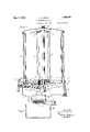
This invention relates more particularly to Fig. 7 (Sheet l) is a partial vertical section dispensers of the type having an uprightl on the line 7 7 of Fig. 6; Y magazine rotatable on a vertical axis for de- Fig. 8 (Sheet 2) is an an enlarged plan liveriiig articles or packages at the bottom. View partly in horizontal section of the magg The machine shown in the accompanying azine stopping and locking device which apsa drawings is designed and constructed for dispears at the left of the center in Fig. l; pensing packages of book matches one pack- Fig. 9 is asimilarly enlarged outer end age at a time, but it should be obvious that View ot a segmental drive gear, together with this machine, either as shown or with slight the cams carried thereby, as viewed from the y alterations therein, could as Well be used oileft in Fig. l. 60 dispensing other more or less similar articles. In the embodiment of the invention shown Also While the dispensing mechanism ot the in the drawings, packages of book matches illustrated machine is Without coin control, l to be dispensed are stacked Within substanit is to be understood that some of the tea tially rectangular hollow vertical columns 15 turcs thereof might be utilized iii a coin con' 2, which form guideways for these packages. o5 trolled machine. i These columns 2 are equidistantly spaced in a Among the objects of the invention are circular series and are shown as radially arsimplicity,economy, effectiveness, reliability, ranged with their longer transverse dimendui'ability and other objects and advantages sions extending radially, for thereby faciliz3 which will hereinafter appear. y tating the delivery of the match packages l, 'I0
The invention includes various features of Which are turned alternately end for end in construction and combinations of parts, as the stack. In the machine shown in the drawwill appear from the following'description ings, the magazine has four ot' these guide of one embodiment thereof which is illuscolumns 2, at right angles to each other and 23; trated in the accompanying drawings. Folrather Widely spaced at the periphery of the 75 lowing the description, the invention Will be magazine. Fach 'of the columns 2 has its pointed out in claims. The illustrated emouter side at the periphery of the magazine, bodimeiit of the invention will now be par` vertically slotted as shown, for the purpose ticularly described, with reference to the of inspection and also for convenience in 3o drawings` in which: filling the magazine. 8G
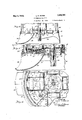
Fig. l is a central vertical section of a At the periphery of the magazine, the ad-v dispensing machine embodying the inven- JglCGD 00111111118 2 are CODIIGVCG. alldfrmly (j0u, On the 1in@ 1 1 0f Fig; 2; tied together by means of straps 3, which are Fig- 2 is a horizontal Section on the una shown as circularly arcuate plates extending 3- 2 2 of Fig'. l. turned counter-clockwise to from near the upper @nds t0 near the lower 8 the extent of 90e: Y ends oi these columns. The upper ends of the columns 2 are firmly and rigidly tied together by means of a notched and flanged "Peral/ing' Partis in a different pOsition; ,pplate 4 Wh-lh lleaves the uppef ,ings of C Fig. 4: is a verticalsection of the lower b e Columns 2 my Open and Whlc a? a 9" mrtsof the machine on the 7564510. line central aperture to form an upper bearing 1 b C for the magazine, which is rotatable on a of Ffg' i, vertical axis. The lower ends of the columns Fig. o is a similar section somewhat Fen:V 2 'are firmly and rigidly tied together by 45 laigedtaken substantially on theline :i o oitl means of ,L lbottom plate 5 which is Centrally a l* ig. 6 and with the delivery mechanism oi perforated. in Ordep to pyovdera, lowar heap the DllClllIle Opllted JCO the QXGR Oi: Sllbforth@ rotatable lnagazin@ The Central stantially a halt-way position; I portion of this bottom plate 5 is spaced above Fig. 6 is a partial horizontal Vsection'. the lower ends of the inner walls of the colviewed from tlieline 6-6 of Fig.` 5; Y unins 2 and is provided With four rectangul" Fig. 3 is a substantially similar section'oii the line 3 3 of Fig. l, but with some of the larly arranged plate extensions 6 which eX- tend down to the lower ends of these inner walls of the columns 2, to which they are firmly secured.
A flat horizontal spider arm 7 projects outwardly from the lower end of each of the down-turned plate parts 6 just below the lower end of the adjacent inner wall-of the vertical `column 2. This spider arm 7constitutes the inner part of a-divided 'bof-tom closure for the column 2. llt will be noted that this spider arm 7 is of less width `than the column 2 and that it is circularly or transversely oifset relatively-to the -column ina counter-clockwise direction, so `that thereby while this spider arm substantially closes the lower end of the 'column at one side, a downwardly opening slot of greater width is left at the oher or Clockwise side. Also it will be noted'that the outer free end of vthis spider arm 7 is circularly rounded and that it terminates before it reaches the middle radially ofthe column 2.
An outer or peripheral bottom part is formed for 'the column 2 by means of a plate 't5 the -fupper surface of which is levelwith Vthe upper surface of the spider arm 7 andthe inner circularly concave end of which is radially spaced from the outer end of the spider arm 7, thereby providing a rather wide circumferential slot radially between these two inner and outer botom closure . parts 7 and 8. This outer closure -plate 8 has upturned flanges as shown, by means of which it is firmly secured to the lower end of the column 2. In operation, the magazine is designed to bey rotated in a counter-clockwise direction as viewed from above. The :lateral or wider side walls of each of the columns 2 have their lowerV ends cut away circumferentially in linewith the slot provided between the spaced ends of thebottom closure parts 7 and 8.
, The liront or leading wall is shown as thus cut away along a straight horizontal line at 9, at a level just above `that of the greatest thickness of a package 1 resting upon the divided botcm closure formed by the radially spaced parts 7 and 8. However, as will'hereinafter appear, the dispensing mechanism would be similarly operable if only a slot should be cut inthe lower edge of this wall in circumferential alignment with and of substantially the same width as the slot provided ` betweenthebottom closure parts 7 and 8. The oher or rear side wall of the column Qis shown as cut away at 10 throughout its width, to form a widely obtuse salient angle.l thereby to provide above the bottom closure sections 7 and 8, a lateral escape slot for a lowermost package 1. regardless of whether itsl tliiclrer'end is at .the front or at vthe rear in the column, while at the same time preventing the escape of the next package 1 above the lowermost. as shown in Fig. 5.
The magazine further includes as a part of its unitary construction, a bottom ring 11, which includes in the same piece therewith a centrally perfor-ated upper end plate 12, which strengthens this ring 11 and forms therewith an inverted cylindrical cup. The top wall 12 of this ring 11 Afits against the lower side lof the magazine bottom plate 5 and the cylindrical periphery of this ring 11 .itself -fits closelyagainst the innersurfacesof the downward extensions 6 of the bottom plate 5, and all of these parts are firmly secured together. All of the several parts of the above described rotatable magazine may be conveniently made .from suitable sheet metal, such as steel, and these parts are all rigidly secured together, such as by means of spot welding.
The magazine bottom ring 11 is a-combined driving and locking ring for the rotatable magazine. This ring and therefore the entire magazine, may be driven and rotated step-by-step in a 'counter-clockwise direction by means of four equidistantly spaced ratchet Yteeth 13, which are shown a-spunched inward from the cylindrical wall-of this ring 11. The lower `edge of 'this ring 11 projects belowthe lower surfacesof the spider arms-7 and is thereprovid'ed with four equidistantly spaced rectangular or square-cornered notches 14, which provide for both .positively stopping and locking the magazine at'fthe itermination of each quarter-turn step of its step-by-step rotative movement.
A central'upright shaft 15, forming a jour-- nal for the rotatable magazine, is rigidly fixed at its vlower end Vin a base vframe 16, which may be a suitable casting, such as a zinc die-casting. A rocking operating member for the magazine has a sleeve 'or hubportion 1.7 pivoted on'theshaft 15, and includes adjacent its upper end a radial pawl-carrying arm 18.and at its lower end further includes a bevel gear segment 19 having outwardly and downwardly directed inclined gear teeth. The lower end of the hub `sleeve '17 rests upon the base frame 16, and the lower end ofthe magazine, which is 4shown as formed by the plate 12, rests upon the upper end of this hub sleeve 17, with the ourna'l shaft 15 eX- tending through the magazine and projecting above its top plate Li, bywhichtogether with the bottom plates 5 and 12, the magazine as a'whole is journaled on this-shaft 15. with the lowerend of this magazine having a suitable clearance above thebase frame 16.
A spring friction washerQO presses down at its periphery on the top plate 4 of the magazine and is anchored to the `journal shaft against rotative movement by means of a cotter pin 21, this cotter pin also holding the vfriction washer 2() down on the magazine top plate L1. The friction on the magazine produced b v this spring' washer QOresults in a more even and regular step-by-step rotative movement of the magazine. In order to render it properly resilient this spring washer is provided around its periphery with radial slots, which do not appear in the drawings. Y
The arm 18 of the rocking operating member 17 is tubular to provide a socket for a cylindrical pawl pin 22, the outer projecting end of which is pressed against the inner side of the ratchet ring 11 by a coiled thrust spring 23 seated in the bottom of this socket and pressing against the inner end of this pawl pin. It is obvious that should the operating member 17 be rocked back and forth to the extent of at least 90, that at each such complete rocking movement, it would impart a quarter turn step of rotation to the magazine, and so on successively. As a matter of fact, and as will presently be described, this operating member 17 is to be thus rocked once at each operation of the machine to anextent of somewhat more than 90, thereby to provide a normal condition of initial lost motion space between the outer end of the pawl pin 22 and the next adjacent ratchet tooth 13 which is to be engaged thereby for driving the ring 11, and therefore the magazine, forward in a counter-clockwise direction, this initial lost motion being utilized for a purpose which will presently appear.
The teeth of the bevel gear segment 19 are engaged by the teeth of a bevel drive gear segment 24 which is located below and forwardly from this bevel gear segment 19. The pitch-line radius of these two intermeshing gears 19 and 24 is the same, although the drive gear 24 is shown as having a few more gear teeth than the magazine-operating gear 19. Therefore, the ratio of these two gears is as one-toone in the mechanism shown. although it would not necessarily need to be just that ratio of drive, provided ofcourse other operating parts yet to be described were changed accordingly. The drive gear sea'- ment 24 is fixed on a handle shaft 25 which is shown as journaled in three bearings in the base frame 16. This handle shaft 25 is in a radial plane with the axis of the magazine journal shaft 15 andis shown as inclined slightly upward in Van outward direction.
The outwardly projecting end of the haudle shaft 25 has a handle knob 26 firmly fixed thereon, such as by casting the handle shaft 25 as an insert into the handle knob 26. as is indicated in Fig. 1. As will presently7 appear, the drive gear segment 24, tog-ether with its handle shaft 25 and handle lrnob 26, is permitted to have only somewhat more. than of to and fro rocking movement. The handle shaft 25 is to be manually rotated in a clockwise direction as viewed from the front of the machine and is returned to its original normal position by means of a torsion spring 27 on the handle shaft, having one of its ends connected thereto and having its other projecting end in engagement with an overlying wall of the base frame 16.
On its front side, which is the back of the gear, the drive gear segment 24 has a hub boss 28. This drive gear 24 carries two cams 29 and 30 which may be die-cast in the same piece therewith, as indicated. The cam 29 is a double cam, that is, having two cam faces. This cam 29 is integrally-joined both to the adjacent face of the drive gear 24 and to its hub 28. This double-faced cam 29 has a front cam face and a peripheral cam face, and this cam 28 as viewed from the front (Fig. 9) appears to be in general of a hook sha-pe with a radially overhanging abrupt end at the right. The front cam face begins at the abrupt or right end of this cam and comprises a wedge portion a which is inclined from the face of the gear forwardly and towards the left where it joins a front or outer fiat cam face portion b. The wedgeshaped end a is an active or operating portion of the front cam face while the iat front face b of the cam rise is a holding portion, The other or peripheral cam face c of this cam 29 extends substantially in spiral form from the gear hub 28 towards the right and outward throughout the circumferential length of this cam 29.
The other cam 30 on the front face of this drive gear 24 is in the form of a forwardly projecting cam lug at the periphery of the gear, extending radially outward beyond the cam 29 and as a whole angularly spaced therefrom to asubstantial extent towards the right (Fig. 9) or clockwise. This cam lug 30 has an active cam face d which is disposed in a plane parallel with the axis of the drive gear 24 and which inclines radially inward and towards the right or clockwise from a point radially outward or above the outer end of the cam 29 to a point radially inward therefrom, so that thereby this inclined cani face d has a radially overlapping relation withthe adjacent ends of both of the cam faces a and c of the cam 29.
At the end of each step of rotative movement of the magazine, it is positively stopped and positively locked against rotative movement in either direction away from its normally inactive position, which is shown for this magazine not only in Figs. 1 and 2, but also in Figs. 3, 4 and 8. This result is accomplished by means of a locking device comprising a horizontal radially slidable latch bolt 31 which is guided in a housing formed in the upper side of the base frame 16, together with a cover plate 32 which is secured to a top plate ofthe bas-e frame 16 by means of screws as shown in the drawings (Figs. 1, 3, 6 and 'I 8). This magazine-locking latch bolt 81 is urged inwardly by a. coiled thrust spring 33 interposed between the outer end of this latch bolt and the outer end wall of its housing in the base plate 16.
eev
This latch bolt 31 projects inwardly beyond its housing and is there provided with an upwardly projecting substantially rectangular locking lug ln the normal position of rest ot the magazine, this locking lug' 34 is engaged in one ot the stop notches 14 in the edge ot the lower end of the magazine ring 11 1, 2, 3 and 3). lt will be noted that there is some tree space (Fig. 1) in this notch 14 above the top or upper end of this locking lng 34. The outer end ot this latch bolt 31 which is engaged b v the spring 33 is of suticient vertical thickness substantially to fill and to have only a sliding lit in the housing `formed by the base plate 16 and the cover plate 32.
From this outer end the latch bolt 31 tapers inwardly on its upper side along a downward incline to the locking lug 34, so that this latch Abolt is there thinner and is spaced below the shaped latch bolt 31 will then rock upon Aits thicker outer end as a pivot. 1t will be noted that the inner end of the cover plate 32 is provided with a rectangular notch (Figs. 1 and 3) in order thereby to provide ample clearance for the locking lug 34 when the latch bolt 31 is slil forward in order to disengage this locking lug 34 from one of the stop notches 14 in the magazine bottom ring 11.
The latch bolt 31 at its inner end adjacent its lower side is provided wita and terminates in a cam follower lug 35 which is in the path of movement ot the drive gear cams '29 and 3G and is normally positioned between these cams and abuts against the adjacent plane or flat forward tace ot the drive gear 24 (Figs. 1, 3 and 8), Vhis 'follower lng 35 on its respective sides horizontally is provided at the left with an inclined cam follower "face e and at the right with an inclined cam follower face rllhe lett hand cani follower 'tace e inclines towards the right both in a rearward direction and also in a radial direction and is substantially complementary to the normally closely acent cam wedge tace a of the cam 29. The opposite or right hand tace 'f ot the cam follower lug 35' inclines only radially outward or upward towards the left and lies in a plane at right angles to the adjacent front tace of the drive gear 24 and parallel with the axis ot this gear, in order thereby to form an abrupt shoulder in this front to rear direction, this ii clined'tace f being substantially complementary rto the inclined cam face d on the cam lng 30.
Normally, under the influence of the re' turn spring 27, the cam lug on the drive gear 24 abats against the cam follower projection 35, which thus serves as a back stop for all of the above described positively connected rocking parts, from the paWl-carrying arm 18 outward to the handle knob 26, thereby positively to limit the reverse movement of these connected parts. When the handle knob 26 is rotated in a clockwise direction, the cam wedge face a of the cam 29 is brought immediately into operating engagement with the inclined face e on the iollower lug 35. By reason of its slightly hook shape, this cam face a of the cam 29, in cooperation with the complementary inclined .tace e on the follower 35, will hold this lug down, to assure the maintenance of its engagement with the cam 29, and will push the latch bolt 31 outward until the inner end ot the cam follower lug 35 -then rides upon the flat front cam face b of the .rotating cam 29. This 'forward sliding lmovement of the latch bolt 31 withdraws its locking lug 34 out of the stop notch 14 in the magazine ring 11, 'thereby unlocking this ring, together with the entire magazine, so the flatter can be rotated.
During this unlocking operation, the magazine yoperating gear- 19 is being rotated and the `pawl 22 is taking up theabove -noted lost motion with the .abrupt end of :the 4next adjacent ratchet tooth 1'3 on the magazinel ring 11. Accordingly, `further rotation of thehandle 26 will rotatezthis ,ring 11 -and' thereby the entire magazine. Further rotation of the cam 29 releases the follower' .lug 35, whereupon the latch bolt spring presses the vrlocking lug 34 against the pe-Y riphery of the magazine ring. 11. 'At the end of a quarter -tn-rn rotation of ,the .maga-v zine this locking lu-g 34 will snap into the next succeeding stop vnotch 14,`thereby bringing'the magazine to a stop and 'locking itat the next normal position ot its intermittent step-by-stcp movement. 'It lis .obviousthat the looking ot the magazine ring 11 will stopl the forward ymovement oit thejhandle knob. 26. lVhen the handle knob V26 .is released, then the handle spring 27 will .return the handle together with all of its positively connected parts. including the drive `gearv 24 and the pawl 22, hack to their original positions. During this reverse movement of these connected parts, the. magazine is maintained in a locked condition Vagainst possible displacement.
lt will be noted that the cam follower lug 35 is now in the return path of the cam 29. As this cam 29 moves reveisely its peripheral spiral cam tace c will ride under the follower lug 35 and litt it, together with the entire inner end ot the latch bolt 31, the locking lug 34 ot this latch bolt, which is engaged ina stop notch 14, then being moved through the chute.
towards the top of this notch while it still remains engaged therein. Near the end of the reverse movement of this cam 29 the cam rise end of its outer cam face c passes beyond and releases the cam follower lug 35. Immediately after this the inclined cam face Z on the cam lug 30 comes into engagement with the complementary inclined face;a on the cam follower lug and draws this lug 35 downward, together with the entire inner end of the latch bolt 31, so that the latter is now again in its original position, in the path of forward movement of the cam 29.
Vhen the inner end of the latch bolt 31 has reached the limit of its downward movement,
'the cam face Z of the cam lug 30 is still in engagement with the face f of the follower lug 35.V This abutting of the cam lug 30 against the follower lug 34 brings all of the above described Vpositively connected operating parts, from the handle 26 inwardly to the drive pawl 22, to a stop in their return movement and at their original positions. During this return movement of these parts, the
drive pawl 22 has ridden over the next following ratchet tooth 13 and has passed beyond the abrupt end of this tooth to an extent for providing the lost motion which is utilized as above described for edecting the unlocking of the magazine ring 11 together with the magazine as a whole.
It will be noted from the drawings that a large right angular open space is left between the successive adjacent columns 2. This free space at the bottom of the magazine is there utilized for eecting the lateral ejection and free delivery of the packages 1. The normal locked position of the four rectangular columns 2 appears most clearly in Fig. 2 and f is indicated in Fig. 3. A delivery chute 36 in the base frame 16 is conveniently located at the front of the machine at the left side of the handle knob 26, with its open upper end at a level just below the bottoms of the columns 2 and in line with the above noted large right angular open space provided between these columns in their normal position of rest.
This delivery chute 36, as will be noted,'is of rather large dimensions transversely, being of considerably greater width than the width of one of the columns 2 (Fig. 6) This large delivery chute thus provides ample free space for a package 1 to escape and freely fall away from the lower end of a column 2,
regardless of any particular position or course` that the package may tend to take in falling away from the bottom of the column 2 from which it has been ejected and down This chute ris shown as of substantially right angular shape at its upper end, with vertical side walls and a downwardly and outwardly concavely curved bottom wall, the outwardly projecting lower end of this chute being shaped to form a convenient reception cup. This entire delivery chute 36 may be cast in the same piece with the base frame 16, as shown.
A stationary ejector lug 37 is mounted upon and projects above the top of the base frame 16 at the right hand side of the top of the delivery chute 36, over which it projects, but leaving the major portion of the top of this chute open. F or convenience in manufacture, the latch bolt cover plate 32 and the ejector lug 37 are shownV as cast in the same piece. This ejector lug 37 1s arcuate and located in line circumferentially with the similarly arcuate open space between the inner and outer parts 7 and 8 of the column bottoms, above which this lug 37 projects substantially to the extent of the thickness of a vsingle package 1. The top of the projecting package in the column. As this column continues to move, this lowermost package will be held stationary by the ejector lug 37 while the column bottom parts 7 and 8 by which this package, as well as those above it, is supported will move out from beneath it. During this package-ejecting operation the lower end 10 of the rea-r Wall of the column 2 moves with a safe clearance above the upper side of this lowermost package which is being delivered but carries along with it the next package above, as well as the entire stack of packages 1 in this column 2. Also atthis time this moving stack of packages will rest upon and be supported by the circularly elongated fiat upper surface of the ejector lug 37, which is shown as of a length almost equal to the width of a column 2.
At the completion of this delivery movement of the magazine, this stack of packages from which one has just been delivered will the bottom of this same column when it again comes around to the ejector lug 37. The same is true, of course, of each of the four columns 2, so that thereby a package 1 will be delivered at each of the quarter turn steps of movement of the magazine. Y
rlhe downward sliding movement of the I projecting out through the vertical slots in the. outer walls of tne columns 2, for the convenient removal of these weights in refilling the columns from the top.
The ejector lug 37 is desirably ot an arcuate length, as shown, for supporting only a single stack of packages, since the lowermost package in a column 2 passing over this lug has frictional sliding engagement therewith While this ejector lug 37 is supporting the entire Stack of packages and its follower weight 38. However,y so :tar as the delivery operation is concerned, this lug 37 could be made very much longer in the counter-clockwise direction of its arcuate extension. in fact, it could` be extended circularly entirely aro-und to the opposite or lett hand wall ot the top ot the delivery chute 36, but not there to project over the delivery chute 3,6, which should be left clear and open for an ejected package to dropinto it. In any case, as soon as a stack of packages is carried beyond the end of the ejector lug. 3f?, this stack will drop upon the columnl bottom walls 7 and 8, with. the lowermost package then in position to be ejected. Inrtheconstruction shown, the stacks of packages, 1j are supported on the inner and outer bottompartsl7 and 8 of the columns 2 and carried; around without friction.
The inner bottom parts T of the columns 2 are formed on the magazine central bottom plate.y 5. as amat-ter oi convenience and economy in manufacture. However, it should be obvious, that similar inner bottom parts for the columns 2 might be differently constructed. For example, such inner bottom closure partscould be constructed in a manner substantially similar to the outer-bottom closure plates 8.
For completing the dispensing machinevot thisinvention in a. commercial and workmanlike manner, a removable unitary protecting and finishing cover is provided for the entire rotatable magazine. rlhis cover comprises a anged base ring 89 firmly secured by means ot an adhesive on the lower cnd of a glass cylinder l0 which has a llanged' sheet. metal top cover l1' similarly firmly secured on its upper end. The magazine journal shaft 15 has a reduced screw threaded end projecting througha central aperture in the cover top Lil, upon which is a cap nut 12, so that the entire magazine cover is securely held in, place with itsllanged bottom ring 39 in engagement with a4 circular rim formed around the top of the base frame 16, as shown.
t is believed that the operation of this dispensing machine, as a Whole and as to its several operating parts, has been already fully described'.
It is'obvious that various modiicationsmay be made in the construction shown in the drawings and above particularly described, within the principle and scope of the invention as defined in the appended claims.
i claim:
1. In a dispenser having a dispensing mechanism including a rotatable part to be driven and also having a rotatable driving member provided with. an operatingA handle, the combination of step-by.step operating mechanism forming anY operating connection between the said rotatable handle member and rotatable part comprising a.l rocking driving member positively connected to the rotatable handle member andV having. a one-way pawl-and-.ratchet driving connection tothe said rotatable part otkthe dispensing mechanism, a positively acting releasable locking device engageable with the said rotatable part of the dispensing mechanism for stopping the latter at the termination ot each step ot` its rotative movement., and Operating means for the said locking device connected to the. said rotatablehandle membenthe said locking. djevice comprising an automatically engaging slidable spring-pressed latch bolt mounted for transverse movement at its engaging end in a plane parallel with the axis of the said rotatable member of the dispensing mechanism and the saidv operating means. for the locking device comprising a double-faced caininounted to rock to and tro past the said latch bolt soI that one face of this cam will push back the latch bolt to its d isengaged position and the other face of this cam will push, the latch bolt aside and", pass it in the return movement of' the cam,
2. 'In a dispenser having a dispensing mechanismy including a rotatable part to be driver-rand also having a rotatable driving member provided with an operating handle, the combination of step-by-st-ep operating mechanism torming an operating connection between the said rotatable handle member and rotatable part comprising a. rocking driving mer-nber` positively yconnected to the rotatable handle member and having a` oneway pawl-and-ratchet driving connection to the said rotatable part of the dispensing mechanism, a positively acting releasable loc-king deviceengageable with the said' rotatable part ot the dispensing mechanism for stoppingthe latter' at the termination of each step of its rotative movement, and operating means for the said locking device connected tothe said rotatable handle member, the said lockingI device comprising an automatically1 engaging slidable spring-pressedl latch bolt mounted', for transverse movement at its. engaging end in a planeparallel' with the axis @seas/Bio ofthe said rotatable member of the dispensing mechanism, and the said operating means for the locking device comprising a doublefaced cam mounted on the handle member to rock to and fro past the said latch bolt so that one face of this cam will push bach the latch bolt to its disengaged position and the lother face of this cam will push the latch bolt aside and pass it in the return movement of the cam, in combination with a second cam carried by the said handle member for restoring the latch bolt to its original lateral position during the final part of the return movement of both cams together with the handle member.
8. The invention defined in claim 2, in which the said latch bolt forms a forward stop for the dispensing` mechanism which it also locks against reverse movement and also through the said pawl-and-ratchet device forms a forward stop for the said handle member, and the said latch bolt also forming a reverse stop for the said rocking driving member and for the handle member through the engagement of this latch bolt by the said second cam in the reverse movement of the latter.
4. In an article dispenser, the combination of a base frame, an upright axis shaft having its lower end Xed in the base frame, a toothed bevel gear journaled on the shaft immediately above the base frame, an upright magazine j ournaled on the shaft above the said gear and including a ring surrounding the latter, the said ring being provided at its inside with a circular series of equidistantly spaced ratchet teeth, an outwardly spring-pressed driving pawl carried by the said gear to rock therewith into engagement with the successive ratchet teeth for thereby imparting step-by-step rotation to the magazine, a manually operable transverse handle shaft journaled in the base frame in a plane radial to the upright axis shaft of the magazine, a toothed bevel drive gear fixed on the handle shaft in engagement with the said gear on the upright shaft, a series of circularly equidistantly spaced locking recesses being provided in the periphery of the said ring, these recesses being equal in number to the said ratchet teeth, an inwardly springpressed locking member mounted on the base frame at the outer side of the said ring to ride upon the outer side of the latter and snap into any one of the said recesses thereby to stop the forward movement of the magazine and to lock it against displacement in either direction at the termination of a step of its rotative movement and thus also limiting the further forward rotation of the handle shaft by reason of the interengaged gears together with the engagement of the said driving pawl with one of the ratchet teeth on the ring, a return spring for the handle shaft and gears and driving pawl, means forming a back stop lfor the driving pawl'o'nly after this pawl release the said locking member so as thereby to permit a forward step of movement of the magazine.
5. The invention delined in claim* 4, in which the said means for releasing the locking member `includes a cam carried by the said drive gear, and in which the said back stop includes a limiting lug also carried by the said drive gear.
6. The invention defined in claim 4, in which the said locking member is a radially slidable latch bolt spring-pressed inwardly to its locking position and mounted in the base frame so that its locking end may be lifted while it is in locking engagement with one of the said locking recesses in the magazine ring, the inner end of the said latch bolt being provided with an inwardly projecting lug shaped to form a cam follower, the said releasing means for the latch bolt comprising a cam projecting from the adjacent front face of the said drive gear and having a front cam face normally positioned for immediately engaging with the said cam follower end of the latch bolt for sliding the latter outward to its disengaged position and also having a peripheral cam face which in the reverse movement of the cam engages beneath the said cam follower end and lifts this end of the latch bolt so that thereby the said cam may return to its original normal position, and the said back stop comprising a forwardly projecting cam lug on the periphery of the adjacent front face of the said drive gear having an inwardly inclined inner cam face to engage over the top of the said cam follower lug thereby to move the engaged latch bolt downward with its cam foli' lower end again immediately in the path of forward movement ,of the said bolt-releasing cam during the final part of the return movement of the drive gear, this return movement being stopped when the locking end of the said latch bolt reaches its downward limit of'movement while the said cam lug is still in engagement with its inwardly projecting follower end.
7. In an article dispenser, the combination of an upright delivery magazine rotatable on a vertical aXis comprising a circular series of equidistantly spaced hollow columns provided with a bottom closure, the lower end of each such column being cut ally along circumferential lines to provide open spaces above the bottom closure and the said bottom closure being divided along circumferential lines into inner and outer radially separated parts so as to leave a slot be- 5- away lateri tweenL such bottom par-ts, a base trane upon which the magazine sV mounted for rotative movement, and a stationary upwardly pro= jeetng ejector lugrigidly .camred'by the base frame to project above the said magazine bottom nrlinerwith thesaid10pen spacesv and slots so that thereby upon rotation;k of: the magazine packages will.v be successively pushed out into the i open,A spaces between; the said columns. f
In Wtnessfwheneofj, I hereunto subscribe my sglmtulee;A
H., MORIN.A
Priority Applications (1)
| Application Number | Priority Date | Filing Date | Title |
|---|---|---|---|
| US408180A US1856780A (en) | 1929-11-19 | 1929-11-19 | Dispensing machine |
Applications Claiming Priority (1)
| Application Number | Priority Date | Filing Date | Title |
|---|---|---|---|
| US408180A US1856780A (en) | 1929-11-19 | 1929-11-19 | Dispensing machine |
Publications (1)
| Publication Number | Publication Date |
|---|---|
| US1856780A true US1856780A (en) | 1932-05-03 |
Family
ID=23615178
Family Applications (1)
| Application Number | Title | Priority Date | Filing Date |
|---|---|---|---|
| US408180A Expired - Lifetime US1856780A (en) | 1929-11-19 | 1929-11-19 | Dispensing machine |
Country Status (1)
| Country | Link |
|---|---|
| US (1) | US1856780A (en) |
Cited By (1)
| Publication number | Priority date | Publication date | Assignee | Title |
|---|---|---|---|---|
| US3136450A (en) * | 1961-11-29 | 1964-06-09 | Internat Vending Machines Inc | Dispensing mechanism |
-
1929
- 1929-11-19 US US408180A patent/US1856780A/en not_active Expired - Lifetime
Cited By (1)
| Publication number | Priority date | Publication date | Assignee | Title |
|---|---|---|---|---|
| US3136450A (en) * | 1961-11-29 | 1964-06-09 | Internat Vending Machines Inc | Dispensing mechanism |
Similar Documents
| Publication | Publication Date | Title |
|---|---|---|
| US2990084A (en) | Vending machine | |
| US1856780A (en) | Dispensing machine | |
| DK142967B (en) | APPARATUS FOR DELIVERING BAGRE | |
| US1189954A (en) | Vending-machine. | |
| US2864532A (en) | Packet merchandising machine | |
| US1697510A (en) | Vending machine | |
| US2684143A (en) | Vending machine coin mechanism | |
| US1946183A (en) | Vending machine | |
| US1982273A (en) | Coin-controlled vending machine | |
| JPS594141B2 (en) | mechanical slot machine | |
| US1922253A (en) | Vending machine | |
| US3056529A (en) | Secondary article dispenser for vending machines | |
| US1344692A (en) | Coin-controlled device for dispensing cups | |
| US1987914A (en) | Dispensing machine | |
| US1357631A (en) | Match-vending machine | |
| US1652540A (en) | morin | |
| US957720A (en) | Coin-operated vending-machine. | |
| US1741387A (en) | Counting mechanism | |
| US2370743A (en) | Vending device | |
| US1922915A (en) | Multiple coin vending machine | |
| US1701869A (en) | Dispensing machine | |
| US1971290A (en) | Ratchet mechanism | |
| US1603576A (en) | Vending machine | |
| US1534273A (en) | Vending machine | |
| US1959084A (en) | Vending machine |