US1856766A - Grain sampler - Google Patents
Grain sampler Download PDFInfo
- Publication number
- US1856766A US1856766A US443359A US44335930A US1856766A US 1856766 A US1856766 A US 1856766A US 443359 A US443359 A US 443359A US 44335930 A US44335930 A US 44335930A US 1856766 A US1856766 A US 1856766A
- Authority
- US
- United States
- Prior art keywords
- grain
- tube
- sample
- sampler
- wall
- Prior art date
- Legal status (The legal status is an assumption and is not a legal conclusion. Google has not performed a legal analysis and makes no representation as to the accuracy of the status listed.)
- Expired - Lifetime
Links
- 241000863032 Trieres Species 0.000 description 1
- 230000000694 effects Effects 0.000 description 1
- 230000000717 retained effect Effects 0.000 description 1
- 238000007789 sealing Methods 0.000 description 1
- 239000002023 wood Substances 0.000 description 1
Images
Classifications
-
- G—PHYSICS
- G01—MEASURING; TESTING
- G01N—INVESTIGATING OR ANALYSING MATERIALS BY DETERMINING THEIR CHEMICAL OR PHYSICAL PROPERTIES
- G01N1/00—Sampling; Preparing specimens for investigation
- G01N1/02—Devices for withdrawing samples
- G01N1/04—Devices for withdrawing samples in the solid state, e.g. by cutting
- G01N1/08—Devices for withdrawing samples in the solid state, e.g. by cutting involving an extracting tool, e.g. core bit
-
- G—PHYSICS
- G01—MEASURING; TESTING
- G01N—INVESTIGATING OR ANALYSING MATERIALS BY DETERMINING THEIR CHEMICAL OR PHYSICAL PROPERTIES
- G01N33/00—Investigating or analysing materials by specific methods not covered by groups G01N1/00 - G01N31/00
- G01N33/0091—Powders
-
- G—PHYSICS
- G01—MEASURING; TESTING
- G01N—INVESTIGATING OR ANALYSING MATERIALS BY DETERMINING THEIR CHEMICAL OR PHYSICAL PROPERTIES
- G01N1/00—Sampling; Preparing specimens for investigation
- G01N1/02—Devices for withdrawing samples
- G01N1/10—Devices for withdrawing samples in the liquid or fluent state
- G01N2001/1006—Dispersed solids
Definitions
- My invention relates to grain samplers whereby a small portion of grain may be taken from a truck or the like for close examination to determine the character and grade of the grain.
- a pan or bucket is employed for scooping up a small quantity of the grain, or a trier is introduced into the body of grain to obtain a sample from the interior of the body.
- the person obtaining the sample must have direct access to the body of grain.
- the person desiring a sample of grain is separated by a wall 5 from the body of grain, for example when a weigher stationed in a scale house desires a sample of the grain contained by a rela tively high-bodied truck positioned on the scales. The weigher must leave his station and go out of the house to the truck to obtain the sample, or open a window to introduce a sampler into the body of grain or to receive a sample extracted by a second party,
- the principal objects of my invention therefore are to mount a sampler in fixed position on a wall adjacent the position of grain to be sampled, to provide a sampler on a scale house that may be manipulated to obtain a sample of grain and deliver the sample to the weigher, and to enable a weigher in a scale house to obtain a sample of grain from a truck positioned on scales exterior to the scale house, without leaving the house or opening windows.
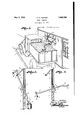
- Fig. 1 is perspective view of portions of a scalehouse and a truck standing on scales adjacent the house, and my improved grain sampler mounted on a wall of the house.
- Fig. 2 is a fragmentary section of the house wall through the device, illustrating the sampler in retracted position for delivering a sample of grain.
- Fig. 3 is a similar viewillustrating the sampler in position to obtain a sample'of gram.
- 1 designates a scale house including a wall 2 provided with a window 3
- 4 designates a scale platform exterior to the house for supporting a truck 5 including a body 6' containing grain, the indicating portion of the scale mechanism (not shown) being 10- F cated with the house adjacent the window.
- My device includes a support 7 comprising preferably a rectangular block of wood adapted to lit snugly but movably in an opening 8 formed in the wall 2 below the window, 7 and may consist of a portion of the wall 7 out out for the purpose,and provided with lateral pivots 9 adjacent the upper edge of the block mounted in suitable bearing recesseslO in the side edges of the opening.
- the upper and lower edges of the block and opening are curved complementarily to promote sealing of the opening when the block registers with the Wall, and to permit the block to pivot freely.
- a tube 12 Rotatively and slidably mounted in a ce-ngo tral aperture 11 in the block, is a tube 12 having an outer end bent laterally to form an elbow 13 and then semi-circularly toform a scoop-like portion 14 extending in a plane A substantially perpendicular to the axis of 5 the body of the tube.
- the outer extremity of the tube is preferably bent. outwardly away from the plane of the portion lt'to provide a scoop-like end portion 15, and the w tip is beveled internally to form a sharp rim 16 at the outer edge of the mouth of the tube.
- the tube may thus be pivoted vertically to introduce the curved outer end in a body of grain in the truck, rotated to collect a sample, and then tilted to effect delivery of )5 the sample into a bucket 17.
- a crank is provided on the inner end of the tube, preferably comprising .a portion 18 bent slightly laterally and an end @00 portion 19 bent into parallelism with the body of the tube.
- a strap 20 fixed to the wall 2 above the window has a hook 21 located to receive the curved portion of the tube, whereby the tube may be retained in retracted position.
- a slanting notch 22 is formed in the inner face of the wall 2 to provide a seat for the tube when the same is retracted.
- a weigher stationed in the house may grasp the crank handle and rotate the tube to release the curved end from the retaining hook, and lift the crank end to move the curved outer end downwardly toward and into the body of grain in the truck. He may then rotate the tube to cause the scoop-like outer end to burrow into the body of grain, and collect a sample from below the surface.
- the sample will consist of a quantity con tained in the curved end portion.
- the tube may then be pivoted to elevate the outer end, and cause the sample of grain contained thereby to flow through the body and crank portion into the bucket.
- the tube may have any desired capacity, and that the curved outer end may be formed in a'manner to collect a desired quantity of grain as a sample.
- a grain sampler including a support, and an imperforate tubular member having one end bent at an angle to the remainder of said member rotatably mounted on the support and adapted to conduct a sample of grain therethrough.
- a support, and an imperforate member having an end bent at an angle to the remainder of said member rotatably and slidably mounted in the support having a channel for conducting a sample of grain or the like through the support.
- a grain sampler including a support, and a tubular member rotatably mounted on the support and having a curved end portion adapted to serve as a scoop when said member is rotated in the support.
- a tube having one end bent to form a scoop and an opposhite end provided with a crank and means for rotatively supporting the tube.
- a tube having one end bent to form a scoop and an opposite end provided with a crank, and pivotal means for rotatively supporting the tube.
- a device of the character described in combination with a wall provided with an opening, a support pivotally mounted in said opening, and a sample collecting member mounted on the support and having a channel for conducting grain from one side of the wall to the other upon pivotal movement of the support.
- a grain sampler in combination with a wall having an'opening, a tube havingone end bent to form a scoop, and means pivotally mounted in said opening having an aperature to receive the tube for relatively supporting the same.
- a grain sampler in combination with a wall having an opening, a tube having one end bent to form a scoop and the opposite end bent to form a crank, and means pivotal- 1y mounted in said opening having an aperture to receive the tube for rotatably and slidably supporting the same.
- a body having a channel and an end portion bent substantially at right angles to the axis of the body, and pivotal means for supporting the body said angular portion serving as a scoop when the body is pivoted on said support.
Landscapes
- Chemical & Material Sciences (AREA)
- Health & Medical Sciences (AREA)
- Life Sciences & Earth Sciences (AREA)
- General Health & Medical Sciences (AREA)
- Analytical Chemistry (AREA)
- Biochemistry (AREA)
- Physics & Mathematics (AREA)
- General Physics & Mathematics (AREA)
- Immunology (AREA)
- Pathology (AREA)
- Engineering & Computer Science (AREA)
- Food Science & Technology (AREA)
- Medicinal Chemistry (AREA)
- Sampling And Sample Adjustment (AREA)
Description
y 1932- H. H. HUNTER l 356,766
GRAIN SAMPLER Filed April 11 1930 Patented May 3, 1932 UNITED STATES HARRY H. HUNTER, 0F ATTIGA, KANSAS GRAIN Application filed April 11,
My invention relates to grain samplers whereby a small portion of grain may be taken from a truck or the like for close examination to determine the character and grade of the grain.
In ordinary practice a pan or bucket is employed for scooping up a small quantity of the grain, or a trier is introduced into the body of grain to obtain a sample from the interior of the body. In either usage, the person obtaining the sample must have direct access to the body of grain. There are numerous situations in which the person desiring a sample of grain is separated by a wall 5 from the body of grain, for example when a weigher stationed in a scale house desires a sample of the grain contained by a rela tively high-bodied truck positioned on the scales. The weigher must leave his station and go out of the house to the truck to obtain the sample, or open a window to introduce a sampler into the body of grain or to receive a sample extracted by a second party,
, any of the courses mentioned involving 1nconvenience, loss of time, and uneconomical expenditure of efiort to obtain the sample, and requiring the use of a sampler that can be carried about and may be misplaced or may not be conveniently available when-required.
The principal objects of my invention therefore are to mount a sampler in fixed position on a wall adjacent the position of grain to be sampled, to provide a sampler on a scale house that may be manipulated to obtain a sample of grain and deliver the sample to the weigher, and to enable a weigher in a scale house to obtain a sample of grain from a truck positioned on scales exterior to the scale house, without leaving the house or opening windows.
In accomplishing these and other objects of my invention, I have provided improved details of structure, the preferred forms of which are illustrated in the accompanylng drawings, wherein:
Fig. 1 is perspective view of portions of a scalehouse and a truck standing on scales adjacent the house, and my improved grain sampler mounted on a wall of the house.
SAMPLER 1930. Serial No. 443,359.
Fig. 2 is a fragmentary section of the house wall through the device, illustrating the sampler in retracted position for delivering a sample of grain.
Fig. 3 is a similar viewillustrating the sampler in position to obtain a sample'of gram.
Referring in detail to'thedrawings:
1 designates a scale house including a wall 2 provided with a window 3, and 4: designates a scale platform exterior to the house for supporting a truck 5 including a body 6' containing grain, the indicating portion of the scale mechanism (not shown) being 10- F cated with the house adjacent the window. 55
My device; includes a support 7 comprising preferably a rectangular block of wood adapted to lit snugly but movably in an opening 8 formed in the wall 2 below the window, 7 and may consist of a portion of the wall 7 out out for the purpose,and provided with lateral pivots 9 adjacent the upper edge of the block mounted in suitable bearing recesseslO in the side edges of the opening. The upper and lower edges of the block and opening are curved complementarily to promote sealing of the opening when the block registers with the Wall, and to permit the block to pivot freely. i
Rotatively and slidably mounted in a ce-ngo tral aperture 11 in the block, is a tube 12 having an outer end bent laterally to form an elbow 13 and then semi-circularly toform a scoop-like portion 14 extending in a plane A substantially perpendicular to the axis of 5 the body of the tube. The outer extremity of the tube is preferably bent. outwardly away from the plane of the portion lt'to provide a scoop-like end portion 15, and the w tip is beveled internally to form a sharp rim 16 at the outer edge of the mouth of the tube.
The tube may thus be pivoted vertically to introduce the curved outer end in a body of grain in the truck, rotated to collect a sample, and then tilted to effect delivery of )5 the sample into a bucket 17.
In order to facilitate operation of the sampler, a crank is provided on the inner end of the tube, preferably comprising .a portion 18 bent slightly laterally and an end @00 portion 19 bent into parallelism with the body of the tube. V
A strap 20 fixed to the wall 2 above the window has a hook 21 located to receive the curved portion of the tube, whereby the tube may be retained in retracted position.
A slanting notch 22 is formed in the inner face of the wall 2 to provide a seat for the tube when the same is retracted.
Attention is called to the fact that the support swings outwardly or inwardly from the wall when the tube is pivoted, due to the location of the pivots above the horizontal median line of the supports, and the notch therefore permits the tube to be swung more nearly into parallel .relation with the wall than would be the case if the crotch were lacking.
In using the device, a weigher stationed in the house may grasp the crank handle and rotate the tube to release the curved end from the retaining hook, and lift the crank end to move the curved outer end downwardly toward and into the body of grain in the truck. He may then rotate the tube to cause the scoop-like outer end to burrow into the body of grain, and collect a sample from below the surface.
The sample will consist of a quantity con tained in the curved end portion. The tube may then be pivoted to elevate the outer end, and cause the sample of grain contained thereby to flow through the body and crank portion into the bucket.
It is apparent that the tube may have any desired capacity, and that the curved outer end may be formed in a'manner to collect a desired quantity of grain as a sample.
What I claim and desire to secure by Letters Patent is:
1. A grain sampler including a support, and an imperforate tubular member having one end bent at an angle to the remainder of said member rotatably mounted on the support and adapted to conduct a sample of grain therethrough.
2. In a device of the character described, a support, and an imperforate member having an end bent at an angle to the remainder of said member rotatably and slidably mounted in the support having a channel for conducting a sample of grain or the like through the support.
3. A grain sampler including a support, and a tubular member rotatably mounted on the support and having a curved end portion adapted to serve as a scoop when said member is rotated in the support.
5. In a device of the character described, a tube having one end bent to form a scoop and an opposhite end provided with a crank and means for rotatively supporting the tube.
6. In a device of the character described, a tube having one end bent to form a scoop and an opposite end provided with a crank, and pivotal means for rotatively supporting the tube.
7. In a device of the character described, in combination with a wall provided with an opening, a support pivotally mounted in said opening, and a sample collecting member mounted on the support and having a channel for conducting grain from one side of the wall to the other upon pivotal movement of the support.
8. In a grain sampler, in combination with a wall having an'opening, a tube havingone end bent to form a scoop, and means pivotally mounted in said opening having an aperature to receive the tube for relatively supporting the same.
9. In a grain sampler, in combination with a wall having an opening, a tube having one end bent to form a scoop and the opposite end bent to form a crank, and means pivotal- 1y mounted in said opening having an aperture to receive the tube for rotatably and slidably supporting the same. 7
In testimony whereof I afiix my signature.
HARRY H. HUNTER.
4. In a device of the character described,
a body having a channel and an end portion bent substantially at right angles to the axis of the body, and pivotal means for supporting the body said angular portion serving as a scoop when the body is pivoted on said support.
Priority Applications (1)
| Application Number | Priority Date | Filing Date | Title |
|---|---|---|---|
| US443359A US1856766A (en) | 1930-04-11 | 1930-04-11 | Grain sampler |
Applications Claiming Priority (1)
| Application Number | Priority Date | Filing Date | Title |
|---|---|---|---|
| US443359A US1856766A (en) | 1930-04-11 | 1930-04-11 | Grain sampler |
Publications (1)
| Publication Number | Publication Date |
|---|---|
| US1856766A true US1856766A (en) | 1932-05-03 |
Family
ID=23760481
Family Applications (1)
| Application Number | Title | Priority Date | Filing Date |
|---|---|---|---|
| US443359A Expired - Lifetime US1856766A (en) | 1930-04-11 | 1930-04-11 | Grain sampler |
Country Status (1)
| Country | Link |
|---|---|
| US (1) | US1856766A (en) |
-
1930
- 1930-04-11 US US443359A patent/US1856766A/en not_active Expired - Lifetime
Similar Documents
| Publication | Publication Date | Title |
|---|---|---|
| US3499327A (en) | Urine collectors | |
| US2852872A (en) | Wheeled shovel | |
| FR2379293A1 (en) | VALVE NEEDLE DEVICE, EQUIPPED WITH INDICATORS, ALLOWING SEVERAL BLOOD TAPS | |
| US1856766A (en) | Grain sampler | |
| US2775844A (en) | Mouse or rat trap | |
| US2652999A (en) | Fishing pole holder | |
| CN204535805U (en) | Notch cuttype measuring cup | |
| US1407068A (en) | Rain gauge | |
| US2082754A (en) | Minnow bucket | |
| US1762347A (en) | Dustless ash shovel | |
| US2137128A (en) | Thief tube | |
| US1350515A (en) | Mail-box | |
| US2233789A (en) | Garbage and waste receptacle | |
| DE929833C (en) | Tiltable transport container for vehicles | |
| CN210128863U (en) | Sampling rod for stool | |
| US2568041A (en) | Garbage receptacle | |
| US9339013B1 (en) | Urine collection device | |
| US2164407A (en) | Dust pan and collector | |
| US3010413A (en) | Particulate material container and dispenser attachment for a rolling pin | |
| US2257672A (en) | Sand sampler | |
| US2218681A (en) | Sanitary drinking dipper | |
| US3151402A (en) | Surveying apparatus for mine shafts | |
| US1629336A (en) | Combined ash and dust pan | |
| FR2599237A1 (en) | APPARATUS FOR MEASURING TIME DIURESE. | |
| US2523624A (en) | Rodent or animal trap |