US1856762A - Steam trap - Google Patents
Steam trap Download PDFInfo
- Publication number
- US1856762A US1856762A US423727A US42372730A US1856762A US 1856762 A US1856762 A US 1856762A US 423727 A US423727 A US 423727A US 42372730 A US42372730 A US 42372730A US 1856762 A US1856762 A US 1856762A
- Authority
- US
- United States
- Prior art keywords
- steam
- trap
- ports
- valve
- outlet
- Prior art date
- Legal status (The legal status is an assumption and is not a legal conclusion. Google has not performed a legal analysis and makes no representation as to the accuracy of the status listed.)
- Expired - Lifetime
Links
- XLYOFNOQVPJJNP-UHFFFAOYSA-N water Substances O XLYOFNOQVPJJNP-UHFFFAOYSA-N 0.000 description 19
- 210000002445 nipple Anatomy 0.000 description 4
- 238000010438 heat treatment Methods 0.000 description 3
- 230000005494 condensation Effects 0.000 description 1
- 238000009833 condensation Methods 0.000 description 1
- 230000008602 contraction Effects 0.000 description 1
- 238000001816 cooling Methods 0.000 description 1
- 230000000694 effects Effects 0.000 description 1
- 239000012530 fluid Substances 0.000 description 1
- 230000002452 interceptive effect Effects 0.000 description 1
- 239000007788 liquid Substances 0.000 description 1
- 239000000463 material Substances 0.000 description 1
- 230000002093 peripheral effect Effects 0.000 description 1
- 230000000284 resting effect Effects 0.000 description 1
- 238000004326 stimulated echo acquisition mode for imaging Methods 0.000 description 1
- 239000000725 suspension Substances 0.000 description 1
Images
Classifications
-
- F—MECHANICAL ENGINEERING; LIGHTING; HEATING; WEAPONS; BLASTING
- F16—ENGINEERING ELEMENTS AND UNITS; GENERAL MEASURES FOR PRODUCING AND MAINTAINING EFFECTIVE FUNCTIONING OF MACHINES OR INSTALLATIONS; THERMAL INSULATION IN GENERAL
- F16T—STEAM TRAPS OR LIKE APPARATUS FOR DRAINING-OFF LIQUIDS FROM ENCLOSURES PREDOMINANTLY CONTAINING GASES OR VAPOURS
- F16T1/00—Steam traps or like apparatus for draining-off liquids from enclosures predominantly containing gases or vapours, e.g. gas lines, steam lines, containers
- F16T1/20—Steam traps or like apparatus for draining-off liquids from enclosures predominantly containing gases or vapours, e.g. gas lines, steam lines, containers with valves controlled by floats
- F16T1/22—Steam traps or like apparatus for draining-off liquids from enclosures predominantly containing gases or vapours, e.g. gas lines, steam lines, containers with valves controlled by floats of closed-hollow-body type
- F16T1/24—Steam traps or like apparatus for draining-off liquids from enclosures predominantly containing gases or vapours, e.g. gas lines, steam lines, containers with valves controlled by floats of closed-hollow-body type using levers
-
- F—MECHANICAL ENGINEERING; LIGHTING; HEATING; WEAPONS; BLASTING
- F16—ENGINEERING ELEMENTS AND UNITS; GENERAL MEASURES FOR PRODUCING AND MAINTAINING EFFECTIVE FUNCTIONING OF MACHINES OR INSTALLATIONS; THERMAL INSULATION IN GENERAL
- F16T—STEAM TRAPS OR LIKE APPARATUS FOR DRAINING-OFF LIQUIDS FROM ENCLOSURES PREDOMINANTLY CONTAINING GASES OR VAPOURS
- F16T1/00—Steam traps or like apparatus for draining-off liquids from enclosures predominantly containing gases or vapours, e.g. gas lines, steam lines, containers
- F16T1/02—Steam traps or like apparatus for draining-off liquids from enclosures predominantly containing gases or vapours, e.g. gas lines, steam lines, containers with valves controlled thermally
- F16T1/08—Steam traps or like apparatus for draining-off liquids from enclosures predominantly containing gases or vapours, e.g. gas lines, steam lines, containers with valves controlled thermally by bimetallic strips or plates
Definitions
- a TTORNEY Patented May 3, 1932 issgaz @FF EEE MARTIN HAUSER, or* Knnsasjotr raisscsjiii ⁇ r-;VA A. ssiterrirfjrof sPEcmnTY COMPANY; or KANSAS" CITY, Yivrrssciurtr; A oofRPoRA'rIN or MISSOURI' Application-sied January. a?, 1930;y seri-a1 :formaran My inventionmrelates to steam traps and more particularly to a device -of that charac- ⁇ ter for controlling. Vflow of steam and Water 1n a steam line.
- thermostatically operated steam traps heretofore available have not' beenfi adapted for independently effecting release of hot Water; the result beingthat-Water drains from the system only when the tem Y' perature in the trap is suliiciently loW- toedect operation of the steam valve, and Watermay collect in the steam ⁇ lineand vinterfere with the free HOW ofsteam and effective employment of steam for heating orother purposes.
- my invention has for its'principal objects 40 to combinethermostatically operated means f-or controlling ⁇ flowof steam-With means for effecting release -of Water, to ⁇ adapt a steam trap for .releasing.wate1, ⁇ to incorporate steam .i control and Water releasing element-s 1in a .45 single structure, and Vto independently i automatiall-y Control( the ⁇ movement of; Steam through a trap vand releaseof-Waterfronigthe tlieawhereby Steam iriasteamflinemay;har free access to all parts ofthe;systembehind-Av a steam-retaining 'tiap, and tothe trap, and water may-be continuously? and automatically'- drained from thesystem Whether thesteam- ⁇ centiollingvalve' l'is open; or closed,-for con! ferring inazkiniuni eliiciencyon the system.
- Fig. 2 is a perspective view of a float-operi4 ated valve and pivotal armf'for supporting afloat.
- Fig; 3 is a-*perspectiveview of aplate'Y pro-f1 vided" with ports respectively 'for steamI landy f 70 Water, and a post-mounted onfthe'plate to sup port-afiioat for controllingrthe AWater'outlet/"v port.
- y Y
- drawings v l and 12- designate portions fof a'steam-line spaced tov receive myf; improved' trap come' prising a hollow bodyforcasingihavingeag side .inlet opening ⁇ i provided With a' curved lower Wall portion ⁇ 5- and -a slant-ingv4 upper Wall portion 6, for directing inlet steam downwardlyl intothe casing, and an 'exteriorV internally 'threaded 4tubular boss around the f openingforming ari-'inlet nipple '7 to receive,-
- the bottom wall is recessed to provide a socket 16, ⁇ and a disk-like plate 17 is pressed into the recess, the disk having ports 18 and 19 slightly smaller respectively than the ports 12 and 13 and concentrically located above the same to cooperate therewith to form outlet passages for steam and water respectively.
- the casing is provided with a relatively large top opening surrounded by an outwardly projecting flange 20 internally screwthreaded to receive the depending skirt 21 of a cap 22.
- a central screwthreaded opening or socket 23 is provided in the cap on the axis of the outlet opening to receive a threaded stud 24 fixed by a base disk 25 to the upper end of a sylphon bellows 26, a stem 27 being dependingly attached to the lower end of the bellows, and the valve 14 comprising a conical head of wear-resisting material screwthreaded into the end of the stem.
- the central portion of the cap is thickened to provide an exterior boss 28 and aiford substantial depth for the socket 23.
- the disk 25 is adapted to firmly engage the lower face of the cap and thus reenforce the upper end wall of the bellows and assist in retaining the bellows in true vertical position.
- the valve 15 consists of a stem having a conical head engageable in the water outlet port of the disk, the stem being pivotally suspended from a lateral projecting ear or lever 29 of a float bracket 30 pivotally mounted on the upper end of a post 31 erected at one edge of the disk.
- the bracket further includes an armv 32 extending above the ear 29 and in the same direction from the post, and having a screwthreaded end 33 an which a globular float 34 is mounted.
- the steam outlet port in the disk, and the post are preferably located on a common diameter of the disk in the vertical plane ot the axis of the inlet, and in order to enable the float arm to move freelywithout interfering with the valve stem 27, the arm is provided with an elongated slot 35 through which the stem 27 extends.
- the float arm thus further provides a guide for the thermostatically operated valve stem and the stem 27 acts as a retaining member to holdthe oat and float K arm in a vertical path.
- the water outlet port in the disk is preferably offset from the common diameter of the steam outlet port and post, and the ear 29 therefore extends in an odset position from the body of the bracket 30.
- thermosat-ically operated valve is located in a plane including the extended axis of the inlet, and that the axis of the float bracket and arm are also in said plane whereby steam entering the trap will bear vertically upon the float in the vertical plane of its movement, and sidewise deflection of the float by steam pressure will be minimized, thus avoiding any interference between the float arm and the thermostatically operated stem which mieht prevent ecient operation of the device,
- the housing may be installed in a steam line, for example in a return line from a heating system, to receive steam,
- a suitable fluid medium is supplied to the bellows to respond to changes in temperature in the casingmember, whereby increase of temperature caused by steam entering through the inlet may result in expansion of the bellows and movement of the valve stem toward the disk to close the port and shut off flow of steam through the trap, to retain steam in the system. Reduction of temperature to a predetermined .degree due to cooling of steam in the system will result in contraction of the bellows and withdrawal of the valve to permit free flow of steam through the trap and effect raising of temperature in the system.
- the float valve controls the independent water outlet comprising the registering ports i opened when supply of steam to the line is suspended, and the trap cools.
- ⁇ Vater accumulating in the trap due to condensation of steam consequent on suspension of steam supply may not rise to a highv enough level to operate the oat for opening the water outlet, but the bellows will contract responsively to lowered temperature in the trap, and withdraw the valve from the steam port to permit all water inthe trap to escape, the line thus being left open to facilitate driving of air therefrom and flow of steam when delivery of steam is resumed.
- a hollow body having a recessed bottom wall provided with a plurality of outlet openings, a plate mounted in said recess and provided with a plurality of ports having smaller diameter than said openings and concentric therewith to form steam and water outlets, a post iiXed to the plate, a float pivotally mounted on the post, a valve pivoted to the arm for controlling one of said outlets, and thermostatically operating means controlling another of said outlets.
- a hollow body having an outlet opening, a plate provided with a plurality of ports covering said opening, a post fixed to the plate, a ioat including a slotted arm pivotally mounted on the post, a valve pivoted to the arm for controlling one of said ports, and thermostatically operating means including a valve stem extending through the slot of said arm controlling another of said ports.
- a hollow body having an outlet opening and a recess substantially defining said opening, a plate provided with a plurality of ports mounted in said recess over said opening, valves controlling said ports, and means including a ioat having pivotal mounting on the plate for controlling the valves.
- a steam trap including a hollow body having an outlet nipple and an apertured web extending across said nipple and provided with a recess, a plate seated in said recess and having ports substantially registering with the apertures in the web, valves controlling said ports, and independently operable means one of which is pivotally mounted on said plate for controlling the valves.
- a steam trap comprising a hollow body having an inlet and an outlet, a web recessed on its upper face extending across said outlet, a central port formed through said web, a second port formed through said web in spaced relation to said first mentioned port, a plate seated in said recess and resting on said web, ports formed through said plate and adapted to register with the ports in said web, an upwardly extending post carried by said plate in radial alignment with said ports, a temperature controlled valve cooperating with one of said ports, a liquid controlled bracket pivotally mounted at one end on said post, and a valve cooperating with the remaining port pivotally carried by said arm.
Landscapes
- Engineering & Computer Science (AREA)
- General Engineering & Computer Science (AREA)
- Mechanical Engineering (AREA)
- Temperature-Responsive Valves (AREA)
Description
-May 3,1932. M. HAUSER y 1,856,762
STEAM TRAP Filed Jan. 27, 1930 BY ,l
A TTORNEY Patented May 3, 1932 issgaz @FF EEE MARTIN HAUSER, or* Knnsasjotr raisscsjiii`r-;VA A. ssiterrirfjrof sPEcmnTY COMPANY; or KANSAS" CITY, Yivrrssciurtr; A oofRPoRA'rIN or MISSOURI' Application-sied January. a?, 1930;y seri-a1 :formaran My inventionmrelates to steam traps and more particularly to a device -of that charac-` ter for controlling. Vflow of steam and Water 1n a steam line.
Itis Well-knownthat Water condensedzinA the supply line of a steam heating system and passing WithsteainV into a trap included in the system Will collect in the line and pa-rticularly in the trap, so that the steam must either pass through the Water or be obstructed i thereby. rraps heretofore .employed have ation of the-other, so that the trap is relieved of Water only When the steam valve is open and steam is floWingrto raise the temperaturey 1n the system.
lt is-desirable to vrender such'steam-con` trolled valves responsive to changes of tem-r perature, but thermostatically operated steam traps heretofore available have not' beenfi adapted for independently effecting release of hot Water; the result beingthat-Water drains from the system only when the tem Y' perature in the trap is suliiciently loW- toedect operation of the steam valve, and Watermay collect in the steam` lineand vinterfere with the free HOW ofsteam and effective employment of steam for heating orother purposes.- Furthermore, a` float valve'forreleasing .Wa-`
ter from a steam'trap operates `only vvhen Water accumulates in the trap, and appreciable amounts ofWater remain in the-trap when the dehveryof steam-1s suspendedand` the trap.. cools.
Inview of fthe conditions'ahove set frth, Y
my invention" has for its'principal objects 40 to combinethermostatically operated means f-or controlling` flowof steam-With means for effecting release -of Water, to` adapt a steam trap for .releasing.wate1,` to incorporate steam .i control and Water releasing element-s 1in a .45 single structure, and Vto independently i automatiall-y Control( the` movement of; Steam through a trap vand releaseof-Waterfronigthe tlieawhereby Steam iriasteamflinemay;har free access to all parts ofthe;systembehind-Av a steam-retaining 'tiap, and tothe trap, and water may-be continuously? and automatically'- drained from thesystem Whether thesteam-` centiollingvalve' l'is open; or closed,-for con! ferring inazkiniuni eliiciencyon the system.
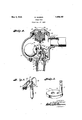
ln accomplishing-theseandother objects of- 5 the invention', l have; provided fim'provedgde 4. tails @f structure, the-gpreferredf-forms of-v whichy are illustrated inf the accompanying' i drawingsg Whereinlzi Y f Fig, lis a'pers'pectivezvie'w off-a'trapvcoi-i'-v structed in accordancewith -my-finvention, in` terposed in `asteamflineg the housing-being shown in ysection.A and parts "of the enclosed'1 elements being 'broken awa-'y tof betterT illus-" trzitetheir1 character.' Y, f
Fig. 2 is a perspective view of a float-operi4 ated valve and pivotal armf'for supporting afloat. y i
Fig; 3 is a-*perspectiveview of aplate'Y pro-f1 vided" with ports respectively 'for steamI landy f 70 Water, and a post-mounted onfthe'plate to sup port-afiioat for controllingrthe AWater'outlet/"v port. y Y
Referringfindetail to the: drawings v l and 12- designate portions fof a'steam-line spaced tov receive myf; improved' trap come' prising a hollow bodyforcasingihavingeag side .inlet opening` i provided With a' curved lower Wall portion `5- and -a slant-ingv4 upper Wall portion 6, for directing inlet steam downwardlyl intothe casing, and an 'exteriorV internally 'threaded 4tubular boss around the f openingforming ari-'inlet nipple '7 to receive,-
the threaded' end of the pipe portion l1, and
an outlet opening-8 -surroujndedby a similar boss 9 internally threaded to* receive the threaded end of the pipe portion '2f Y The-bottom-Wall l0 of the casing. extends across the inner end of the outlet` 8 to form a web 11 provided Awith a central port l2-on lillV the axis of the casing and a smaller port 13 adjacent the periphery of the outlet 8 and communicating therewith, the ports comprising respectively a steam outlet and a water outlet from the trap controlled by independently actuated valves including a thermostatically actuated valve 14 `and a float-actuated valve 15, presently described in detail.
In order to reenforce the web and provide suitable seats for the valves at the entrance to the outlets, the bottom wall is recessed to provide a socket 16,`and a disk-like plate 17 is pressed into the recess, the disk having ports 18 and 19 slightly smaller respectively than the ports 12 and 13 and concentrically located above the same to cooperate therewith to form outlet passages for steam and water respectively.
ln order to support the valve 14 and operate the same to control the steam port, the casing is provided with a relatively large top opening surrounded by an outwardly projecting flange 20 internally screwthreaded to receive the depending skirt 21 of a cap 22. A central screwthreaded opening or socket 23is provided in the cap on the axis of the outlet opening to receive a threaded stud 24 fixed by a base disk 25 to the upper end of a sylphon bellows 26, a stem 27 being dependingly attached to the lower end of the bellows, and the valve 14 comprising a conical head of wear-resisting material screwthreaded into the end of the stem. The central portion of the cap is thickened to provide an exterior boss 28 and aiford substantial depth for the socket 23.
The disk 25 is adapted to firmly engage the lower face of the cap and thus reenforce the upper end wall of the bellows and assist in retaining the bellows in true vertical position.
The valve 15 consists of a stem having a conical head engageable in the water outlet port of the disk, the stem being pivotally suspended from a lateral projecting ear or lever 29 of a float bracket 30 pivotally mounted on the upper end of a post 31 erected at one edge of the disk. The bracket further includes an armv 32 extending above the ear 29 and in the same direction from the post, and having a screwthreaded end 33 an which a globular float 34 is mounted. 1
The steam outlet port in the disk, and the post, are preferably located on a common diameter of the disk in the vertical plane ot the axis of the inlet, and in order to enable the float arm to move freelywithout interfering with the valve stem 27, the arm is provided with an elongated slot 35 through which the stem 27 extends. The float arm thus further provides a guide for the thermostatically operated valve stem and the stem 27 acts as a retaining member to holdthe oat and float K arm in a vertical path.
The water outlet port in the disk is preferably offset from the common diameter of the steam outlet port and post, and the ear 29 therefore extends in an odset position from the body of the bracket 30.
Attention is called to the position of the recess 16 and the disk 17 in the bottom of the casing, the center of the recess being eccentrically located with reference to the axis of the casing, and the peripheral portion of the disk which supports the post being located in the base of the boss which forms the outlet nipple, to provide sturdier structure.
The portion of the casing wall opposite the inlet is formed arcuately and bulges outwardly to provide a recess for the float. Attention is further called to the fact that the thermosat-ically operated valve is located in a plane including the extended axis of the inlet, and that the axis of the float bracket and arm are also in said plane whereby steam entering the trap will bear vertically upon the float in the vertical plane of its movement, and sidewise deflection of the float by steam pressure will be minimized, thus avoiding any interference between the float arm and the thermostatically operated stem which mieht prevent ecient operation of the device,
In using the device, the housing may be installed in a steam line, for example in a return line from a heating system, to receive steam,
and trap the same for retaining steam in the system and controlling flow thereof through the system.
A suitable fluid medium is supplied to the bellows to respond to changes in temperature in the casingmember, whereby increase of temperature caused by steam entering through the inlet may result in expansion of the bellows and movement of the valve stem toward the disk to close the port and shut off flow of steam through the trap, to retain steam in the system. Reduction of temperature to a predetermined .degree due to cooling of steam in the system will result in contraction of the bellows and withdrawal of the valve to permit free flow of steam through the trap and effect raising of temperature in the system.
The float valve controls the independent water outlet comprising the registering ports i opened when supply of steam to the line is suspended, and the trap cools.
`Vater accumulating in the trap due to condensation of steam consequent on suspension of steam supply may not rise to a highv enough level to operate the oat for opening the water outlet, but the bellows will contract responsively to lowered temperature in the trap, and withdraw the valve from the steam port to permit all water inthe trap to escape, the line thus being left open to facilitate driving of air therefrom and flow of steam when delivery of steam is resumed.
What I claim and desire to secure by Letters Patent is l. in a steam trap, a hollow body having an inlet and a plurality of outlet ports, a thermostatically controlled valve including a stem and a bellows mounted on the inner wall of the body controlling one of said ports, a float having an arm provided with a slot to permit said stem to pass therethrough pivotally mounted in the body, and a valve operable by said float controlling another of said ports, the slotted arm and stem co-acting to keep the valves aligned with their respective ports.
2. In a steam trap, a hollow body having a recessed bottom wall provided with a plurality of outlet openings, a plate mounted in said recess and provided with a plurality of ports having smaller diameter than said openings and concentric therewith to form steam and water outlets, a post iiXed to the plate, a float pivotally mounted on the post, a valve pivoted to the arm for controlling one of said outlets, and thermostatically operating means controlling another of said outlets.
3. In a steam trap, a hollow body having an outlet opening, a plate provided with a plurality of ports covering said opening, a post fixed to the plate, a ioat including a slotted arm pivotally mounted on the post, a valve pivoted to the arm for controlling one of said ports, and thermostatically operating means including a valve stem extending through the slot of said arm controlling another of said ports.
4. In a steam trap, a hollow body having an outlet opening and a recess substantially defining said opening, a plate provided with a plurality of ports mounted in said recess over said opening, valves controlling said ports, and means including a ioat having pivotal mounting on the plate for controlling the valves.
5. A steam trap including a hollow body having an outlet nipple and an apertured web extending across said nipple and provided with a recess, a plate seated in said recess and having ports substantially registering with the apertures in the web, valves controlling said ports, and independently operable means one of which is pivotally mounted on said plate for controlling the valves.
6. A steam trap comprising a hollow body having an inlet and an outlet, a web recessed on its upper face extending across said outlet, a central port formed through said web, a second port formed through said web in spaced relation to said first mentioned port, a plate seated in said recess and resting on said web, ports formed through said plate and adapted to register with the ports in said web, an upwardly extending post carried by said plate in radial alignment with said ports, a temperature controlled valve cooperating with one of said ports, a liquid controlled bracket pivotally mounted at one end on said post, and a valve cooperating with the remaining port pivotally carried by said arm.
In testimony whereof I aiiiX my signature.
MARTIN HAUSER.
Priority Applications (1)
| Application Number | Priority Date | Filing Date | Title |
|---|---|---|---|
| US423727A US1856762A (en) | 1930-01-27 | 1930-01-27 | Steam trap |
Applications Claiming Priority (1)
| Application Number | Priority Date | Filing Date | Title |
|---|---|---|---|
| US423727A US1856762A (en) | 1930-01-27 | 1930-01-27 | Steam trap |
Publications (1)
| Publication Number | Publication Date |
|---|---|
| US1856762A true US1856762A (en) | 1932-05-03 |
Family
ID=23679970
Family Applications (1)
| Application Number | Title | Priority Date | Filing Date |
|---|---|---|---|
| US423727A Expired - Lifetime US1856762A (en) | 1930-01-27 | 1930-01-27 | Steam trap |
Country Status (1)
| Country | Link |
|---|---|
| US (1) | US1856762A (en) |
-
1930
- 1930-01-27 US US423727A patent/US1856762A/en not_active Expired - Lifetime
Similar Documents
| Publication | Publication Date | Title |
|---|---|---|
| US2117056A (en) | Steam trap | |
| US1856762A (en) | Steam trap | |
| US2208181A (en) | Vacuum air valve | |
| US3104677A (en) | Brine valves | |
| US2146731A (en) | Steam radiator valve | |
| US757873A (en) | Valve. | |
| US1915661A (en) | Vacuum air valve | |
| US1813401A (en) | Temperature regulator | |
| US1505032A (en) | Automatically-controlled valve | |
| US3011752A (en) | Liquid level control valve | |
| US1237252A (en) | Valve for use in heating systems. | |
| US2300962A (en) | Method and apparatus for heating buildings | |
| US2023073A (en) | Water feeder | |
| US3485266A (en) | Combined vent and overflow means for an enclosed fluid containing vessel | |
| US1708622A (en) | Air-relief and vacuum check valve for steam radiators | |
| US1884857A (en) | Steam trap | |
| US1490940A (en) | Air valve | |
| US543034A (en) | Automatic water-regulator | |
| US1588919A (en) | Steam trap | |
| US1845634A (en) | Radiator and air valve therefor | |
| US398778A (en) | gunckel | |
| US1983218A (en) | Heating system | |
| US1162347A (en) | Gas-regulator. | |
| US1799259A (en) | Blast trap | |
| US1123480A (en) | Radiator-valve. |