US1856727A - Electrode - Google Patents
Electrode Download PDFInfo
- Publication number
- US1856727A US1856727A US352706A US35270629A US1856727A US 1856727 A US1856727 A US 1856727A US 352706 A US352706 A US 352706A US 35270629 A US35270629 A US 35270629A US 1856727 A US1856727 A US 1856727A
- Authority
- US
- United States
- Prior art keywords
- tube
- seal
- electrode
- shield
- wire
- Prior art date
- Legal status (The legal status is an assumption and is not a legal conclusion. Google has not performed a legal analysis and makes no representation as to the accuracy of the status listed.)
- Expired - Lifetime
Links
- 239000007789 gas Substances 0.000 description 23
- 238000012856 packing Methods 0.000 description 20
- 239000000463 material Substances 0.000 description 13
- 239000011521 glass Substances 0.000 description 8
- 239000010425 asbestos Substances 0.000 description 6
- 229910052895 riebeckite Inorganic materials 0.000 description 6
- 239000004020 conductor Substances 0.000 description 5
- VYPSYNLAJGMNEJ-UHFFFAOYSA-N silicon dioxide Inorganic materials O=[Si]=O VYPSYNLAJGMNEJ-UHFFFAOYSA-N 0.000 description 5
- 239000000377 silicon dioxide Substances 0.000 description 4
- -1 Boro silica Chemical compound 0.000 description 3
- 239000007772 electrode material Substances 0.000 description 3
- 238000007747 plating Methods 0.000 description 3
- 229910052729 chemical element Inorganic materials 0.000 description 2
- 238000010276 construction Methods 0.000 description 2
- 238000005336 cracking Methods 0.000 description 2
- 239000000835 fiber Substances 0.000 description 2
- 239000005355 lead glass Substances 0.000 description 2
- 238000007789 sealing Methods 0.000 description 2
- 238000009736 wetting Methods 0.000 description 2
- WYUYEJNGHIOFOC-VVTVMFAVSA-N 2-[(z)-1-(4-methylphenyl)-3-pyrrolidin-1-ylprop-1-enyl]pyridine;hydrochloride Chemical compound Cl.C1=CC(C)=CC=C1C(\C=1N=CC=CC=1)=C\CN1CCCC1 WYUYEJNGHIOFOC-VVTVMFAVSA-N 0.000 description 1
- UFHFLCQGNIYNRP-UHFFFAOYSA-N Hydrogen Chemical compound [H][H] UFHFLCQGNIYNRP-UHFFFAOYSA-N 0.000 description 1
- 230000002939 deleterious effect Effects 0.000 description 1
- 239000002657 fibrous material Substances 0.000 description 1
- 238000010438 heat treatment Methods 0.000 description 1
- 229910052739 hydrogen Inorganic materials 0.000 description 1
- 239000001257 hydrogen Substances 0.000 description 1
- 238000004519 manufacturing process Methods 0.000 description 1
- 238000000034 method Methods 0.000 description 1
- 239000010445 mica Substances 0.000 description 1
- 229910052618 mica group Inorganic materials 0.000 description 1
- 229910052754 neon Inorganic materials 0.000 description 1
- GKAOGPIIYCISHV-UHFFFAOYSA-N neon atom Chemical compound [Ne] GKAOGPIIYCISHV-UHFFFAOYSA-N 0.000 description 1
- 229910052756 noble gas Inorganic materials 0.000 description 1
- 239000000615 nonconductor Substances 0.000 description 1
- 239000002245 particle Substances 0.000 description 1
- 238000003825 pressing Methods 0.000 description 1
- 230000001846 repelling effect Effects 0.000 description 1
- 239000007787 solid Substances 0.000 description 1
- 238000001228 spectrum Methods 0.000 description 1
- 238000004804 winding Methods 0.000 description 1
Images
Classifications
-
- H—ELECTRICITY
- H01—ELECTRIC ELEMENTS
- H01J—ELECTRIC DISCHARGE TUBES OR DISCHARGE LAMPS
- H01J61/00—Gas-discharge or vapour-discharge lamps
- H01J61/02—Details
- H01J61/30—Vessels; Containers
- H01J61/32—Special longitudinal shape, e.g. for advertising purposes
Definitions
- Another object of my invention isto employ this packing as a means for preventing
- the shield must therefore be loose electrical contact between the electrode and the deposited electrode material on the shield the electrode chambers in the vicinity of the vtllbe and thus Prevent Such d p i ed m electrodes. If the area which is subject to this deposit is large, the rate with which the gases are imprisoned thereunder is high. If this area is reduced in size, the rate of entrapment of the gas is slowed up to a negligible degree. To accomplish this result, a tubular glass shield is supported in' the electrode chamber about the electrodeas. the deposit receiver. The inside diameter of this shield is a little larger than the outside diameter of the electrode so as to reduce to the minimum the area to receive the deposit from the electrode. v
- the shield will not crack to expose the electrode to excessive bombardment or enlarge the deposit receiving area to increase the rate of entra ment of the gas to shortenthe life of the tu e.
- the seal tube for closing the end of the electrode chamber is made of the same glass as the main outer tube so that the two may be joined by fusing.
- the boro silica shield rial from becoming a. source of electrical emission to increase the area of the original electrode. I accomplish this result by making the acking of a material which will not conduo? an electrical current and which will not take a plating of the sputtered material from the electrode.
- the invention consists further in the structural features hereinafter described and claimed and also in the method of applying and treating the packing in the making of the electrode unit.
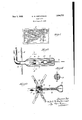
- Fig. l is a face view of an electric si the characters of which are in the form luminescent gas discharge tubes provided with electrodes ,of my invention.
- Fig. 2 1s a lon ltudmal sectional new through the electro e end of one of the tubes
- the bulbs 3 are at the opposite ends of the tube and are usually disposed" at right angles thereto and e'xtendinto the is dischar' ed into the tube to ionize the gas confined t erein.
- the gas employed may be neon or any other of the rare gases of the Noble gas group which are used in these tubes for illuminating them.
- the electrode chambers 3 of each tube are sealed so that a high vacuum may be produced in the tube as required for tubes of this character.
- the seal at each end of a tube is made through the use of a seal tube 6 which is made separate from the main tube 1 and afterwards inserted therein.
- the seal tube 6 and theou'ter tube 1 are usuall made of lead glass so that both tubes may be connected or joined together by fusing at the outer end of the seal tube.
- the inner end of the seal tube 6 is closed by fusing to provide a'vacuum seal? for the outer tube 1.
- Electric current for the electrode element 5 is carried by a lead-in wire 8 which is sealed in the seal 7 and is connected by spot weldin or otherwise to the.element 5.
- the wire 8 supports the electrode element 5 out of contact with the seal 7 so that the differences in expansion of the electrode ma terial and of the glass seal 7 in the operation of the electrode will not crack or break the seal to allow the gas confined in the tube to escape and put out the tube. Supporting the element 5 in this way, the portions a, b of the wire are exposed between the element and the seal 7. To shield these portions of the wire from the bombardment to which the electrode element 5 is subject when in use and thus prevent cutting-off of the wire, I surround the wire with a packing 9 of a material which will not conduct an electrical current and which will also resist heat.
- a tubular glass shield 11 Arranged about the element 5 is a tubular glass shield 11 which is considerably smaller in diameter than the electrode chamber 3 so as to be relatively close to the electrode 5 and thus lessen the intensity of the bombardment to which the electrode is subject and also to reduce to the minimum the area exposed to receive the sputtered material from theelectrode.. This, therefore slows up the rate of entrapment of the gas in the tube in the sputtered electrode material and prolongs the life of the tube even when usingsmall electrodes of the size heretofore referred to.
- the shield 11 being close to the electrode element 5 is subject to the hi h temperature produced at the electrode w en processing the tube, as well as when operating it in use.
- a shield of this material has a lower co-efficient of expansion than the soft glass of the outer and the seal tubes 1 and 6 and can not be fused thereto.
- the shield 11 is therefore loose with respect to the outer and the seal tubes and I employ the packing 9 to support the loose shield in place.
- I give the packing 9 an outside diameter sufiicient to fit relatively tight in the shield to support it in place.
- the packing is in the form of an asbestos strip, as shown, I have the number of layers of the wrapping sufiicient to give the packin the outside diameter required.
- the shiel tube 11 may be made relatively long so as" to extend substantially the full length of the electrode chamher 3 from a point close to the outer end of the seal tube to the construction y where the chamber joins the main body of the tube 1 with this arrangement the shield tube is prevented from undue shifting in the main tube as the latter is handled.
- the packing 9 fitting in the shield tube 11 provides a dead end for the gas in the shield tube and being a non-conductor of electrical X packing 9.
- the packing 9 will not take a plating of sputtered material from the electrode 5, because the packing has the dielectric property of absorbing a charge of the same polarity as the electrode with which the packing is used. This results in the induced charge on the packing repelling the vaporized particles omitted'from the electrode and.
- the packing 9 will not allowthe area of such electrode being increased by the sputtered material deposited on the shield. This is an important "feature because it reduces the rate of gas entrapment even with small electrodes which are subject to a more intense bombardment than the large electrodes.
- the electrode unit of my invention is simple in construction, cheap and eas to make, and in use. It is especially.
- An electrode unit for luminescent gas discharge tubes comprising a seal tube having its inner end closed to form a seal, an electrode element at the inner end of said seal tube, a lead-in wire sealed in said seal and supporting the element out of contact therewith, and a packing of non-conducting material wrapped about and completely enclosing the portion of the wire between the element and the seal.
- An electrode unit for luminescent gas discharge tubes comprising a seal tube having its inner end closed to form a seal, an electrode element at the inner end of said seal tube, a lead-in wire sealed in said seal and supporting the element out of contact therewith, and a packing olt non-conducting material non-conducting material wrapped aboutand completely enclosing the portion of the wire between the element and the seal, said strip having its starting end engaged in the loop of said wire.
- An electrode unit for luminescent gas discharge tubes comprising a seal tube closed at its inner end to form, a seal, an electrode element at the inner end of said seal tube; a lead-in wire sealed in said seal and supporting the element out of contact therewith, a shield tube about said element and extending along and beyond the ends of the same,
- An electrode unit for luminescent gas discharge tubes comprising a sealtube closed atits inner end to form a seal, an electrode element at the inner end of said seal and supporting the element out of contact therewith, a shield tube about said element and extending over the seal tube beyond the seal thereof, and a packing of non-conducting material enclosing the portion of the wire between the element and the seal and extending out to the shield tube to support the same at said ele- -ment, said seal tube having an enlargement beyond its seal to provide a support for the portion of the shield tube thereover.
- An electrode unit for luminescent gas discharge tubes comprising a seal tube having its inner end closed to form a seal, an electrode element at the inner end of said seal 'tube, a lead-in wire sealed in said seal and supporting the element out of contact there: with, a shield tube about said element, and a de-gasified packing of asbestos enclosing the portion of the wire between the element and the seal and extending outward to said shield tube to support the same.
Landscapes
- Vessels And Coating Films For Discharge Lamps (AREA)
Description
y 1932- R. w. REITHERMAN 7 1,856,727
ELECTRODE Filed April 5, 1929 J Patented May 3, 1932 UNITED STATES PATENT OFFICE BAL PE W. REITHERMAN, .OF OAK PARK, ILLINOIS, ASSIGNOR TO FLASHTRIG SIGN WORKS, A COPABTNERSHIP COMPOSEID OF FRED PARKER HARRY S. PARKER,
BOTH OF CHICAGO, ILLINOIS ELECTRODE Application filed April 5,
mprisoned under the vaporized or sputteredmaterial which is deposited on the walls of 1929. Serial No. 852,706.
either. with respect to the seal and the outer tubes, and it is an object of my invention to provide a novel means of supporting the shield in the electrode chamber about the electrode and the seal tube. To accomplish this, I provide a packing fitting relatively tight in the shield tube at the base of the electrode to support the shield tube from the seal tube.
Another object of my invention isto employ this packing as a means for preventing The shield must therefore be loose electrical contact between the electrode and the deposited electrode material on the shield the electrode chambers in the vicinity of the vtllbe and thus Prevent Such d p i ed m electrodes. If the area which is subject to this deposit is large, the rate with which the gases are imprisoned thereunder is high. If this area is reduced in size, the rate of entrapment of the gas is slowed up to a negligible degree. To accomplish this result, a tubular glass shield is supported in' the electrode chamber about the electrodeas. the deposit receiver. The inside diameter of this shield is a little larger than the outside diameter of the electrode so as to reduce to the minimum the area to receive the deposit from the electrode. v
The soft glass from which the outer tube is made can not be usedfor this deposit receiver or shield because the shield being close to the electrode would melt and crack from the high temperatures developed at the electrode during the processing of the tube. 'One object of my inventionis to overcome this. I
do so by making the shield of a material which will withstand without cracking these high temperatures. Boro silica is a material which will withstand these temperatures and I accordingly make the shield of this material.v With this material, the shield will not crack to expose the electrode to excessive bombardment or enlarge the deposit receiving area to increase the rate of entra ment of the gas to shortenthe life of the tu e.
The seal tube for closing the end of the electrode chamber is made of the same glass as the main outer tube so that the two may be joined by fusing. The boro silica shield rial from becoming a. source of electrical emission to increase the area of the original electrode. I accomplish this result by making the acking of a material which will not conduo? an electrical current and which will not take a plating of the sputtered material from the electrode.
The invention consists further in the structural features hereinafter described and claimed and also in the method of applying and treating the packing in the making of the electrode unit. a
In the accompanying drawings- Fig. l is a face view of an electric si the characters of which are in the form luminescent gas discharge tubes provided with electrodes ,of my invention.
Fig. 2 1s a lon ltudmal sectional new through the electro e end of one of the tubes,
propriate glass tubing bent to the shape desired and having enlarged and elongated bulb-like end portions 3 which form the chambers for the internal electrodes of the characters. The bulbs 3 are at the opposite ends of the tube and are usually disposed" at right angles thereto and e'xtendinto the is dischar' ed into the tube to ionize the gas confined t erein. The gas employed may be neon or any other of the rare gases of the Noble gas group which are used in these tubes for illuminating them.
The electrode chambers 3 of each tube are sealed so that a high vacuum may be produced in the tube as required for tubes of this character. The seal at each end of a tube is made through the use of a seal tube 6 which is made separate from the main tube 1 and afterwards inserted therein. The seal tube 6 and theou'ter tube 1 are usuall made of lead glass so that both tubes may be connected or joined together by fusing at the outer end of the seal tube. The inner end of the seal tube 6 is closed by fusing to provide a'vacuum seal? for the outer tube 1. Electric current for the electrode element 5 is carried by a lead-in wire 8 which is sealed in the seal 7 and is connected by spot weldin or otherwise to the.element 5.
The wire 8 supports the electrode element 5 out of contact with the seal 7 so that the differences in expansion of the electrode ma terial and of the glass seal 7 in the operation of the electrode will not crack or break the seal to allow the gas confined in the tube to escape and put out the tube. Supporting the element 5 in this way, the portions a, b of the wire are exposed between the element and the seal 7. To shield these portions of the wire from the bombardment to which the electrode element 5 is subject when in use and thus prevent cutting-off of the wire, I surround the wire with a packing 9 of a material which will not conduct an electrical current and which will also resist heat. Mica r and asbestos will do this and when asbestos is employed, as shown inthe drawings, I use it in flat strip form of a width to fill the space between the element 5 and the seal 7. The asbestos strip is first wetted and then wrapped in the form of a coil about the wire andhas a suflicient number of convolutions or-layers to completely enclose the wire and shield it from the bombardment referred to. The end of the wire 8 at the electrode ele ment 5 is bent into the form of a loop to provide the prong b in which the starting end of the asbestos strip is engaged to hold the strip as it is wound about the wire. Wetting the strip makes it pliable for winding and also permits the wrapped layers to be pressed or squeezed together to bring the fibers of the strip into intimate contact. After the strip is woundfit is heated to in candescence by hydrogen flames 10, 10 to drive off the moisture and otherwise de-gasify the material to make a more or less solid integral mass which will not give 'ofi any deleterious gases orsubstance to mask the spectrum of the gas confined in the tube when the latter is put in use.
Arranged about the element 5 is a tubular glass shield 11 which is considerably smaller in diameter than the electrode chamber 3 so as to be relatively close to the electrode 5 and thus lessen the intensity of the bombardment to which the electrode is subject and also to reduce to the minimum the area exposed to receive the sputtered material from theelectrode.. This, therefore slows up the rate of entrapment of the gas in the tube in the sputtered electrode material and prolongs the life of the tube even when usingsmall electrodes of the size heretofore referred to.
The shield 11 being close to the electrode element 5 is subject to the hi h temperature produced at the electrode w en processing the tube, as well as when operating it in use.
The soft lead glass shields heretofore employed melt and crack under these high temperatures, and to avoid this I make the shield of boro silica which will withstand these temperatures without cracking or breaking. A shield of this material has a lower co-efficient of expansion than the soft glass of the outer and the seal tubes 1 and 6 and can not be fused thereto. The shield 11 is therefore loose with respect to the outer and the seal tubes and I employ the packing 9 to support the loose shield in place. To accomplish this, I give the packing 9 an outside diameter sufiicient to fit relatively tight in the shield to support it in place. When the packing is in the form of an asbestos strip, as shown, I have the number of layers of the wrapping sufiicient to give the packin the outside diameter required. The shiel tube 11 may be made relatively long so as" to extend substantially the full length of the electrode chamher 3 from a point close to the outer end of the seal tube to the construction y where the chamber joins the main body of the tube 1 with this arrangement the shield tube is prevented from undue shifting in the main tube as the latter is handled.
The packing 9 fitting in the shield tube 11 provides a dead end for the gas in the shield tube and being a non-conductor of electrical X packing 9. The packing 9 will not take a plating of sputtered material from the electrode 5, because the packing has the dielectric property of absorbing a charge of the same polarity as the electrode with which the packing is used. This results in the induced charge on the packing repelling the vaporized particles omitted'from the electrode and.
preventing plating of the electrode material on the exposed surface of the packing to establish electrical contact between the electrode and the deposited material on the surrounding wall of the shield 11. Manifestly the area of the electrode element 5 is not increased, beyond that as originally provided therefor, during the operation of the tube and the rate of gas entrapment is not increased. Thus, when using a relatively small electrode element, such as one having an area not exceeding 1.5 square decimeters per ampere, the packing 9 will not allowthe area of such electrode being increased by the sputtered material deposited on the shield. This is an important "feature because it reduces the rate of gas entrapment even with small electrodes which are subject to a more intense bombardment than the large electrodes.
The lead-in wires being in contact with the electrodes 'absorb heat, this heat being Suficient to destroy the union formed by the cupric and silica oxides between the "glass and the lead-in wires. In accordance with my invention, I make the seals relatively long as shown at 7 in Figs. 2 and 3, so that a sumciently long length of wire is enclosed in the seal that the latter will not be afiected by the condition referred to and therefore will not allow the gas to leak through the seals about the wires, as heretofore.
With the shield 11 extending over the seal tube 6 beyond its seal 7, I provide the seal tube with an enlargement to fit against the adjacent portion of the shield and thus aid in supporting it in the outer tube.
The electrode unit of my invention is simple in construction, cheap and eas to make, and eficient in use. It is especially.
- suitable for small electrodes, and effectively performs the functions for which it is designed.
The details of structure and arrangement of parts shown and described may be variously changed and modified without departing from the spirit and scope of 'my invention.
I claim as my invention:
1. An electrode unit for luminescent gas discharge tubes, comprising a seal tube having its inner end closed to form a seal, an electrode element at the inner end of said seal tube, a lead-in wire sealed in said seal and supporting the element out of contact therewith, and a packing of non-conducting material wrapped about and completely enclosing the portion of the wire between the element and the seal.
2. An electrode unit for luminescent gas discharge tubes, comprising a seal tube having its inner end closed to form a seal, an electrode element at the inner end of said seal tube, a lead-in wire sealed in said seal and supporting the element out of contact therewith, and a packing olt non-conducting material non-conducting material wrapped aboutand completely enclosing the portion of the wire between the element and the seal, said strip having its starting end engaged in the loop of said wire. r 4. An electrode unit for luminescent gas discharge tubes, comprising a seal tube closed at its inner end to form, a seal, an electrode element at the inner end of said seal tube; a lead-in wire sealed in said seal and supporting the element out of contact therewith, a shield tube about said element and extending along and beyond the ends of the same,
and a packing of non-conducting material completely enclosing the portion of the wire between the element and the seal and extending out to the shield tube t9 support the same.
5. An electrode unit for luminescent gas discharge tubes, comprising a sealtube closed atits inner end to form a seal, an electrode element at the inner end of said seal and supporting the element out of contact therewith, a shield tube about said element and extending over the seal tube beyond the seal thereof, and a packing of non-conducting material enclosing the portion of the wire between the element and the seal and extending out to the shield tube to support the same at said ele- -ment, said seal tube having an enlargement beyond its seal to provide a support for the portion of the shield tube thereover.
6. An electrode unit for luminescent gas discharge tubes, comprising a seal tube having its inner end closed to form a seal, an electrode element at the inner end of said seal 'tube, a lead-in wire sealed in said seal and supporting the element out of contact there: with, a shield tube about said element, and a de-gasified packing of asbestos enclosing the portion of the wire between the element and the seal and extending outward to said shield tube to support the same.
7. The methodof making an electrode unit for luminescent gas discharge tubes, consistint ing in sealing alead-in wire in a seal tube,
gasify the layers and unite them in a relatively compact mass.
8. The method of making an electrode unit for luminescent gas discharge tubes, consisting in sealing a lead-in wire in a seal tube,-c0nmeeting the wire to an electrode element at the inner end of said seal tube, wetting a strip of non-conducting fibrous material and then wrapping the same in the form of a coil about the portion of the wire between the element and the seal tube until the wrapping extends out beyond the base of the element, then pressing the wet layers together to' interlock the fibers thereof, and finally heating the wrapped layers to in'candescence tov de-gasify the layers and unite them in a relatively compact mass.
9. lhe combination with an electrode chamber of a luminescent gas discharge tube, I a seal tube extending into said chamber and oined thereto at its outer end, said seal tube aving its inner end closed to provide a vacmun-mal for said chamber, an electrode element in said chamber at the inner end of said seal tube, a lead-in wire for said element and sealed in said seal, a shield tube in said chamher about said element and extending substantially the full length of said chamber, said shield tube being loose with respect to said chamber and said seal tube, and means carried by the seal tube for supporting the shield tube in said chamber.
In testimony whereof I affix my signature.
RALPH W. REITHERMAN.
assaye
Priority Applications (1)
| Application Number | Priority Date | Filing Date | Title |
|---|---|---|---|
| US352706A US1856727A (en) | 1929-04-05 | 1929-04-05 | Electrode |
Applications Claiming Priority (1)
| Application Number | Priority Date | Filing Date | Title |
|---|---|---|---|
| US352706A US1856727A (en) | 1929-04-05 | 1929-04-05 | Electrode |
Publications (1)
| Publication Number | Publication Date |
|---|---|
| US1856727A true US1856727A (en) | 1932-05-03 |
Family
ID=23386157
Family Applications (1)
| Application Number | Title | Priority Date | Filing Date |
|---|---|---|---|
| US352706A Expired - Lifetime US1856727A (en) | 1929-04-05 | 1929-04-05 | Electrode |
Country Status (1)
| Country | Link |
|---|---|
| US (1) | US1856727A (en) |
-
1929
- 1929-04-05 US US352706A patent/US1856727A/en not_active Expired - Lifetime
Similar Documents
| Publication | Publication Date | Title |
|---|---|---|
| US2322421A (en) | Electric discharge lamp | |
| JPH01134849A (en) | Arc discharge lamp with electrodeless ultraviolet starter | |
| US3780331A (en) | Apparatus and method for eliminating microcracks in alumina ceramic discharge devices | |
| US2847605A (en) | Electrode for fluorescent lamps | |
| US2477372A (en) | Electric gaseous discharge lamp | |
| US2492619A (en) | Electrical discharge tube | |
| US2093567A (en) | Thermionic tubes and the manufacture thereof | |
| US2451043A (en) | Gas discharge lamp | |
| US1856727A (en) | Electrode | |
| US3422300A (en) | Ceramic arc tube and closure member construction | |
| US2138224A (en) | Method of sealing electrical conductors into vitreous envelopes | |
| US3351803A (en) | Seal and lead-in conductor assembly for gaseous discharge lamps | |
| US2188298A (en) | Seal for evacuated devices | |
| US2241345A (en) | Electron emissive cathode | |
| US2748309A (en) | Gas or vapor discharge tube | |
| US2598241A (en) | Electric discharge device | |
| US2068596A (en) | Vapor discharge device | |
| EP2149146B1 (en) | High pressure sodium lamp | |
| US1957423A (en) | Vacuum tube for heavy currents | |
| US2076286A (en) | Electric gaseous discharge device | |
| US2020724A (en) | Gaseous electric discharge lamp device | |
| US2128051A (en) | Electric discharge apparatus | |
| US1636054A (en) | Electrical discharge device | |
| US1906037A (en) | Electrode in discharge tubes | |
| US2080914A (en) | Gaseous electric discharge lamp |