US1856697A - Slide buckle - Google Patents
Slide buckle Download PDFInfo
- Publication number
- US1856697A US1856697A US554438A US55443831A US1856697A US 1856697 A US1856697 A US 1856697A US 554438 A US554438 A US 554438A US 55443831 A US55443831 A US 55443831A US 1856697 A US1856697 A US 1856697A
- Authority
- US
- United States
- Prior art keywords
- buckle
- frame
- plane
- slide
- intermediate bar
- Prior art date
- Legal status (The legal status is an assumption and is not a legal conclusion. Google has not performed a legal analysis and makes no representation as to the accuracy of the status listed.)
- Expired - Lifetime
Links
- 239000002184 metal Substances 0.000 description 10
- 229910052751 metal Inorganic materials 0.000 description 10
- 150000002739 metals Chemical class 0.000 description 9
- 230000002441 reversible effect Effects 0.000 description 3
- 238000003466 welding Methods 0.000 description 3
- 238000005219 brazing Methods 0.000 description 2
- 238000004519 manufacturing process Methods 0.000 description 2
- 230000004048 modification Effects 0.000 description 2
- 238000012986 modification Methods 0.000 description 2
- 238000005476 soldering Methods 0.000 description 2
- 238000005452 bending Methods 0.000 description 1
- 230000015572 biosynthetic process Effects 0.000 description 1
- 238000000926 separation method Methods 0.000 description 1
Images
Classifications
-
- A—HUMAN NECESSITIES
- A44—HABERDASHERY; JEWELLERY
- A44B—BUTTONS, PINS, BUCKLES, SLIDE FASTENERS, OR THE LIKE
- A44B11/00—Buckles; Similar fasteners for interconnecting straps or the like, e.g. for safety belts
- A44B11/02—Buckles; Similar fasteners for interconnecting straps or the like, e.g. for safety belts frictionally engaging surface of straps
- A44B11/04—Buckles; Similar fasteners for interconnecting straps or the like, e.g. for safety belts frictionally engaging surface of straps without movable parts
-
- Y—GENERAL TAGGING OF NEW TECHNOLOGICAL DEVELOPMENTS; GENERAL TAGGING OF CROSS-SECTIONAL TECHNOLOGIES SPANNING OVER SEVERAL SECTIONS OF THE IPC; TECHNICAL SUBJECTS COVERED BY FORMER USPC CROSS-REFERENCE ART COLLECTIONS [XRACs] AND DIGESTS
- Y10—TECHNICAL SUBJECTS COVERED BY FORMER USPC
- Y10T—TECHNICAL SUBJECTS COVERED BY FORMER US CLASSIFICATION
- Y10T24/00—Buckles, buttons, clasps, etc.
- Y10T24/40—Buckles
Definitions
- the structure differs from either of the struc-tures previously disclosed in that, while the buckle frame is of substantially rectangular form, the intermediate bar structure is formed of a sepiratc piece of wire and secured and maintained within the plane of the frame by means of uniting in permanent intimate union the engaging metals of both ext e1 iities of the intermediate bar structure with a side struc- "'Lure.
- the ob]ects of the invention therefore are to provide a substantially rectangular buckle frame with an intermediate bar structure angularly bent out of the buckle plane Mand having connections to the frame wholly vvithin the buckle plane; to provide such a frame with an intermediate bar structure having angular bends out of the buckle plane and of which both extremities engage a sice structure of the frame, and the engaging metals united in permanent intimate union;
- the frame 1 is preferably made ofwire" bent into substantially rectangular form having upper and lower horizontal bars, Q'and! 3, respectively, and side structures. tand-5, so that the wire ends 6 and 7 are made to abut in the formation of one of the side structures,v as in the middle of the side structure 4f.
- the intermediate bar structure v ⁇ 8 is preferably l made by bending a piece of wire in the middley and thenback upon itself to provide the associated bars 9 and '10 having the free eX- tremities 12 and 13 at one end and the looped extremity 14 at lhe other end, each of these bars 9 and 10 being provided with a series of angular bendsI extending in opposite directions out of the commonplane of the ybars 9 and 10 to provide the projections 11.
- rhe intermediate bar structure 8 is placed within the-buckle frame so that each of its extremities12-13 and 14: will engage, within the plane of the frame 1, the middle of a side structure i or 5.
- the parts 1 and 8, thus associated, may be relatively secured, together With the abutting Wire ends 6 and 7, in any desired manner, but it is preferred that the engaging metals of the looped extremity 14 and the side structure 5 be united in permanent intimate union, as by Welding, brazing or soldering, as at 15 designated by the dotted enclosure, and the engaging metals of the abut-ting Wire ends 6 and 7, Within the side structure 4, together with the engaging metals of the extremities 12-13, are united in permanent intimate union, as by Welding, brazing or soldering, as at 16 designated by the dotted enclosure.
- the dotted enclosures as at 15 and 16 being the convenient places for Welding in the automatic production of the device.
- the parts 1 and 8, thus united, provide a slide buckle that is reversible in that an upright elevation reverse to that illustrated by the Figure 1 is identical therewith, and also provide a slide buckle that is indestructible in that the union of the engaging metals is so permanent that the original character of the metal surfaces cannot be restored by any means effecting a mere separation of the parts.
- the Figure 4 illustrates a modification of the preferred form of the device and differs therefrom only in that the intermediate bar structure 8A comprises a. single bar angularly bent out of the plane of the frame 1A.
- the modified slide buckle parts 8A and 1A are made reversible and indestructible as in the preferred form by means of uniting the structural connections and parts in permanent intimate union, as aforesaid With regard to the preferred form of the device.
- a slide buckle comprising a substantially rectangular frame having upper, lower and side structures, and a separate intermediate bar structure having extremities each perma-A nently secured in intimate union, WithinV the planeof the frame, to an inner surface of said side structures, the intermediate bar structure having spaced projections extending in opposite directions out of said plane.
- a slide buckle comprising a substantially rectangular frame having upper, lower and side structures, and a separate intermediate bar structure having extremities each engaging, Within the plane of the frame, an inner surface of said side structures, the intermediate bar structure having spaced projections extending in opposite directions out of said plane, and the engaging metals of said extremities and said side structures being relatively secured in permanent intimate union.
- a slide'buckle comprising a substantially rectangular Wire frame having in one common plane upper and lower horizontal bars and side bar structures, the Wire ends abutting in one side structure, and intermediate plane.
Landscapes
- Adornments (AREA)
Description
May 3, 1932- 1. H. DOMKEE 1,855,697
SLIDE BUCKLE Filed Aug.v 1, 1951 rl El 4 AT-Vy Patented May 3, 1932 UfNfr-ren fififftiiil @Fretten-fa JOHN-.H.-DOMKEE, OF WEST HAVEN, CONNECTCUT, ASSGNOR-TO THE WIRE NEJV'ElLTYl MANUFACTURING COMPANY, 0F WEST HAVEN, CONNECTTCUT, A CORPORATION A0.11"
CONNECTICUT SLIDE BUCKLE Application filed August l,
5o provide a slide of the pair of loops type connected at one side and free at the opposite sides with intermediate bars angularly bent out of the buckle plane, the engaging metals of the free sides, and also the extremities of 'the intermediate bar structure in engagement with the connected side, being united in permanent intimate union, but in the device disclosed by the application the slide com- 1Vprised separate units of substantially reclangular form of which pairs are associated in a common plane and thus united in permanent intimate union to provide a slide buckle of which the intermediate bars are angularly bent out of the buckle plane. ln the device herein disclosed, however, the structure differs from either of the struc-tures previously disclosed in that, while the buckle frame is of substantially rectangular form, the intermediate bar structure is formed of a sepiratc piece of wire and secured and maintained within the plane of the frame by means of uniting in permanent intimate union the engaging metals of both ext e1 iities of the intermediate bar structure with a side struc- "'Lure. The ob]ects of the invention therefore are to provide a substantially rectangular buckle frame with an intermediate bar structure angularly bent out of the buckle plane Mand having connections to the frame wholly vvithin the buckle plane; to provide such a frame with an intermediate bar structure having angular bends out of the buckle plane and of which both extremities engage a sice structure of the frame, and the engaging metals united in permanent intimate union;
1931.' semina. 554,438.
and-to provide a substantially rectangular.v buckle frame from apiece of wire the endsi of which abut within a side structure, and an intermediate bar structure havingian-gu-` lar bends out of the buckle planefand of which both'extremities engage' a side structure'ofv the frame, the metals thus engaging within and at the side structures being united in permanent intimate union. lilith these and other objects in view as may become-apparent from' the within disclosures, the invention consists not only of the particular formherein pointed outand illustrated in the drawings" but readily admits'of certain modification withinthescope Vof what hereinafter maybe claimed. y
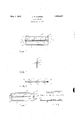
The character of the invention may bebes'tf understood by referenceto one illustrative deviceembodying the invention and'illustrated by the accompanying drawings inwhich the Figure l is an upright elevation ofthe device the Figure 2 is an upright side elevationcfI the device; and the Figure 3 is 'across-section upon the dotted line 3 3 of the Figure 1, the Figure 4 being an -uprightfelevatien of a. modi'liedform ofthe device.
Referring more particularly to the drawingsgtlie improved slide buckle is m-ade'- in two parts of which each partis made'from'a separate lpiece of wire or other desire'dmaterial. The frame 1 is preferably made ofwire" bent into substantially rectangular form having upper and lower horizontal bars, Q'and! 3, respectively, and side structures. tand-5, so that the wire ends 6 and 7 are made to abut in the formation of one of the side structures,v as in the middle of the side structure 4f. The intermediate bar structure v` 8 is preferably l made by bending a piece of wire in the middley and thenback upon itself to provide the associated bars 9 and '10 having the free eX- tremities 12 and 13 at one end and the looped extremity 14 at lhe other end, each of these bars 9 and 10 being provided with a series of angular bendsI extending in opposite directions out of the commonplane of the ybars 9 and 10 to provide the projections 11. rhe intermediate bar structure 8 is placed within the-buckle frame so that each of its extremities12-13 and 14: will engage, within the plane of the frame 1, the middle of a side structure i or 5. The parts 1 and 8, thus associated, may be relatively secured, together With the abutting Wire ends 6 and 7, in any desired manner, but it is preferred that the engaging metals of the looped extremity 14 and the side structure 5 be united in permanent intimate union, as by Welding, brazing or soldering, as at 15 designated by the dotted enclosure, and the engaging metals of the abut-ting Wire ends 6 and 7, Within the side structure 4, together with the engaging metals of the extremities 12-13, are united in permanent intimate union, as by Welding, brazing or soldering, as at 16 designated by the dotted enclosure. The dotted enclosures as at 15 and 16 being the convenient places for Welding in the automatic production of the device. The parts 1 and 8, thus united, provide a slide buckle that is reversible in that an upright elevation reverse to that illustrated by the Figure 1 is identical therewith, and also provide a slide buckle that is indestructible in that the union of the engaging metals is so permanent that the original character of the metal surfaces cannot be restored by any means effecting a mere separation of the parts. The Figure 4 illustrates a modification of the preferred form of the device and differs therefrom only in that the intermediate bar structure 8A comprises a. single bar angularly bent out of the plane of the frame 1A. The modified slide buckle parts 8A and 1A are made reversible and indestructible as in the preferred form by means of uniting the structural connections and parts in permanent intimate union, as aforesaid With regard to the preferred form of the device.
I claim 1. A slide buckle comprising a substantially rectangular frame having upper, lower and side structures, and a separate intermediate bar structure having extremities each perma-A nently secured in intimate union, WithinV the planeof the frame, to an inner surface of said side structures, the intermediate bar structure having spaced projections extending in opposite directions out of said plane.
2. A slide buckle comprising a substantially rectangular frame having upper, lower and side structures, and a separate intermediate bar structure having extremities each engaging, Within the plane of the frame, an inner surface of said side structures, the intermediate bar structure having spaced projections extending in opposite directions out of said plane, and the engaging metals of said extremities and said side structures being relatively secured in permanent intimate union.
A slide'buckle comprising a substantially rectangular Wire frame having in one common plane upper and lower horizontal bars and side bar structures, the Wire ends abutting in one side structure, and intermediate plane.
JOHN H. DOMKEE.
Priority Applications (1)
| Application Number | Priority Date | Filing Date | Title |
|---|---|---|---|
| US554438A US1856697A (en) | 1931-08-01 | 1931-08-01 | Slide buckle |
Applications Claiming Priority (1)
| Application Number | Priority Date | Filing Date | Title |
|---|---|---|---|
| US554438A US1856697A (en) | 1931-08-01 | 1931-08-01 | Slide buckle |
Publications (1)
| Publication Number | Publication Date |
|---|---|
| US1856697A true US1856697A (en) | 1932-05-03 |
Family
ID=24213323
Family Applications (1)
| Application Number | Title | Priority Date | Filing Date |
|---|---|---|---|
| US554438A Expired - Lifetime US1856697A (en) | 1931-08-01 | 1931-08-01 | Slide buckle |
Country Status (1)
| Country | Link |
|---|---|
| US (1) | US1856697A (en) |
-
1931
- 1931-08-01 US US554438A patent/US1856697A/en not_active Expired - Lifetime
Similar Documents
| Publication | Publication Date | Title |
|---|---|---|
| US2002946A (en) | Buckle and process of making same | |
| US1856697A (en) | Slide buckle | |
| US2272524A (en) | Work support for laundry tubs | |
| US1836923A (en) | Slide buckle | |
| US1856698A (en) | Slide buckle | |
| US1836959A (en) | Slide buckle | |
| US412953A (en) | Mount for photographs | |
| US1925500A (en) | Support | |
| US642558A (en) | Picture-frame. | |
| US593868A (en) | Spring-clamp for wire-fence stays | |
| US1885240A (en) | Slide buckle | |
| US282286A (en) | dikema | |
| US2164464A (en) | Fastening means | |
| US2403712A (en) | Slide loop | |
| US2016941A (en) | Picture frame | |
| US1702345A (en) | Ornamental protecting grille | |
| US1840770A (en) | Slide buckle | |
| US1664109A (en) | Article holder | |
| US1894855A (en) | Slide buckle | |
| US539135A (en) | Frame for pictures | |
| US547469A (en) | Picture-frame | |
| US1776493A (en) | Slide buckle | |
| US1844274A (en) | Slide buckle | |
| US2197358A (en) | Guide mounting | |
| US443514A (en) | Curtain-pole ring |