US1856694A - Apparatus for covering articles - Google Patents
Apparatus for covering articles Download PDFInfo
- Publication number
- US1856694A US1856694A US404036A US40403629A US1856694A US 1856694 A US1856694 A US 1856694A US 404036 A US404036 A US 404036A US 40403629 A US40403629 A US 40403629A US 1856694 A US1856694 A US 1856694A
- Authority
- US
- United States
- Prior art keywords
- sheet
- core
- pyroxylin
- seat
- chest
- Prior art date
- Legal status (The legal status is an assumption and is not a legal conclusion. Google has not performed a legal analysis and makes no representation as to the accuracy of the status listed.)
- Expired - Lifetime
Links
Images


Classifications
-
- B—PERFORMING OPERATIONS; TRANSPORTING
- B29—WORKING OF PLASTICS; WORKING OF SUBSTANCES IN A PLASTIC STATE IN GENERAL
- B29C—SHAPING OR JOINING OF PLASTICS; SHAPING OF MATERIAL IN A PLASTIC STATE, NOT OTHERWISE PROVIDED FOR; AFTER-TREATMENT OF THE SHAPED PRODUCTS, e.g. REPAIRING
- B29C51/00—Shaping by thermoforming, i.e. shaping sheets or sheet like preforms after heating, e.g. shaping sheets in matched moulds or by deep-drawing; Apparatus therefor
- B29C51/16—Lining or labelling
-
- B—PERFORMING OPERATIONS; TRANSPORTING
- B29—WORKING OF PLASTICS; WORKING OF SUBSTANCES IN A PLASTIC STATE IN GENERAL
- B29C—SHAPING OR JOINING OF PLASTICS; SHAPING OF MATERIAL IN A PLASTIC STATE, NOT OTHERWISE PROVIDED FOR; AFTER-TREATMENT OF THE SHAPED PRODUCTS, e.g. REPAIRING
- B29C51/00—Shaping by thermoforming, i.e. shaping sheets or sheet like preforms after heating, e.g. shaping sheets in matched moulds or by deep-drawing; Apparatus therefor
- B29C51/10—Forming by pressure difference, e.g. vacuum
Definitions
- My invention relates to a method and anapparatus for coating an article, particularly a. toilet seat, with a sheet of pyroxylin.
- One object of my invention is to provide a method and an apparatus in which suction is utilized to wrap a sheet of pyroxylin about a core.
- Another object sheet of pyroxylin is subjected to the action of heatwhereby it is rendered plastic, and also to a partial vacuum for wrapping the sheet about a core.
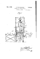
- ig. 1 is a front elevational view of a machine embodying my invention and by which my process may be carried out, the parts being shown in the position they occupy after the sheet has been drawn about the core;
- Fig. 2 is a sectional view on the line 22of- Fig. 1, parts being broken
- Fig. 3 is a sectional view 1;
- ig. 4 is a sectional view on the line 4-4 of Fig. 2, parts being broken away;
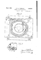
- Fig. 5 is a sectional view showing the core in an inverted position together with those parts immediately adjacent the core, parts being broken away.
- lhe illustrated machine comprises a pair of clamping plates 1 and 2 for gripping a sheet of pyroxylin 3 therebetween, a chest or receptacle 4 adapted to receive steam or hot air to render the pyroxylin sheet plastic; a bottom plate 5, and a seat 6 carried thereby for supporting a core 7 in position to be by the pyroxylin sheet.
- the lower clamping secured to a frame 8 on a plurality of supporting posts 9 and has a gasket 10 thereon.
- The. upper clamping plate 2 is carried by a iramell which is 12. Guides-13 on a head 14 supported by the posts 9 are provided for directing the movement 101 the rods 12.
- the rods are connected at their top by a cross-bar 15 which is secured to a rod 16 ⁇ on thereto and the of my invention is to pr0-- vide a method and an apparatus in which a plate 1 is detachably.
- a pipe 20 communicates with the steam chest orreceptacle 4 for admittingsteam chest is provided with an outlet 21 for the emission of steam, so that siibstantially no pressure develops in the c est.
- the plate 22 is secured to a rod 23 actuable by a piston 24 which is reciprooable in a cylinder 25 by means of fluid' admitted through pipes 26 and 27
- the seat 6 has a chamber 28 therein which is covered by a plate 30 constituting a portion of the seat and on which the .core 7 is secured by means of ,ret ining pins 31 projecting upwardly from the seat-into core.
- llhe seat is also provided with a plurality of small ducts 32 which are placed along-the outer periphery of the core 7.
- the core is provided with a central openin as in the case of a toilet seat, w is the orm of core illustrated in the draw ings, the ducts 32 are also provided on the inner edge of the core.
- the chest is secured to a plate 22which the body of the hich '
- the seat 6 is also provided with an opening 33 which communicates with the chamber 28 and also with a pipefid carried by the bottomplate 5.
- the pipe 34 commu-m- 5 and interposed between it and the clamping late 1 and a pair of knockout pins 36 proect upwardly through the bottom plate, 5 and through openings in I gage the bottom of the core 7 for forcing it ofl he retaining pins 31 after the wrapping operation is completed.
- the knock-out pins 36 are mounted on a plate 37 which is connected by a rod 38 to a piston 40 in a cylinder 41 and fluid is admissible into the lower part of the cylinder .through' a port 42 for raising the seat 6 and .en-
- the plate 37 is retractable by means of-sprin 43 which extend between it and the carrier 44 to which the cy der 41 is secured
- the carrier may be engaged and moved up and down by a head 46 actuable by a piston 47 which reciprocates: in a cylinder 48 on a block 50.
- the carrier is provided with wheels 51 which on its downward movement are engageable with tracks 52 mounted .on the posts 8 to permit the carrier to be rolled laterally,
- a rod 53 is provided on the carrier, projecting downwardly and slidable upwardly and downwardly through 'an' eye 54 in the which is reciprocable by means of a piston 56 in a cylinder 57.
- e carrier 44 is movable laterally from in dotted lines in Fig. 1 tillit is directly over the head 46 and has a from the clamping plate 1. the lower end of the guide being tapered slightly so that as the carrier is moved upwardly it will be caused to center more accurately: in posit on.
- Fig. 5 illustrates an arrangement of parts used when the core -7 is inverted so that the sheet of pyroxylin may be applied to its upturned .bottom. 4
- a seat 61 of somewhat'diflerent shape is here provided having a peripheral recess 61' in which the core is mounted. restingon bolts 62 which are ad- 'justable in posit on.
- a clamping member 64' issubstituted for the clamping plate 1 on the frame 8 Y
- the sheet of pvroxvlin 3 is placed on the clamping plate 1 and the clamping plate 2 is then brought down bvmeans of the piston 17 and the rod 18 until t engages the peripherwof is thus securelv retained;
- the steam chest or receptacle 4 is then lowered until its lower edge engages the clamping plate 2. Steam s then admitted to the chest and the sheet of pyroxylin is thus made plastic.
- the carrier 5 mav at this time be in the position illustrated in dotted l nes in Fig. 1.
- the particular seatdesired is placed on the chine may be used for coating objects of various shapes, and accordinglv seats of different shapes may be provided; Furthermore. even in coating a core of the shape illustrated, either the bottom or the top may be first covered, and therefore either seat 6 or seat 61 may be first placed on the carrier. It is assembled by merely lowering it onto. the
- pyroxylin coating is next assembled by means of the iston 56 and t ⁇ to stretch and to a guide depending to guide the sheet underneath the
- the steam chest or receptacle is next moved edges substitilted in the seat and center it in position.
- the piston 56and the head 46 are then moved upwardly, bringing the latter into en- T gagement with the carrier 44, raising it and the parts associated with it, thus causing the core 7 to engage the pyroxy sheet 3 and to move upwardly into the steam chest 4 to the position'shown in Fig. 2, the upward movement of the core causing the pyroxylin sheet begin to wrap about the core.
- Suction is then applied to the chamber 28 by means of the suction pump, and the air is evacuated on the lower side of the sheet, thus drawing it downwardly.
- the location of the ducts is such that the sheet is drawn inwardly; about the lower edges of the core, the shape of the seat being such as core.
- the pyroxylin sheet is next trimmed away
- the core being thus 7 v the mafrom the edges ofthe core and the seat 61 is forthe'clamping plate 1.
- Another applicationof cement-is then made on the bottom of the core along its edges and it is then placed in the seat 61 in an inverted position as shown in Fig. 5.
- the clamping member 64' is substituted on the frame 8 in place of clamping plate 1 and thesheetof pyroxylin 64 is placed thereon.
- a new cycle of operations is then performed, substantially in the manner abovedescrilied, and. the new sheet of pyroxylin is drawn snugly against the bottom of the core.
- the core is removed from the machine and the pyroxylin sheet is trimmed away from its edges.
- the surface of a core coated by the dechest may be mounted fixedly in position, and the clamping plates may be moved upwardly into cooperative relation therewith.
- a device for coating a core with a sheet oi pyroxylin the combination of means for holding said sheet about its periphery, a fixed support for said means, a movable heating chest having an open end, a support for said core movable into position to constitute a closure for said chest with said sheet interposed therebetween as a partition, said support having openings for the discharge of air from the space on one side of said sheet, means for moving said chest and said movable support into said position, and means for producing a condition of lesser pressure on the 'side of said sheet at which said movable support is located whereby said sheet, being plastic because of the action'of said heating chest, is drawn about and around the edges of said core.
- a device for coating a core with a sheet of pyroxylin the combination of a plurality of fixed guides, a clamp member fixed on said guides and having an enlarged opening there- 80 in, a similar clamp member mounted for sliding movement into a position for gripping said sheet of pyroxylin between it and said fixed clamp member, a heating chest having an open end, means for raising said chest or lowering it into engagement with said slidable clamp member, a support for said core mounted for lateral movement to and from a position beneath said sheet, said supportbeing upwardly movable from a position beneath 4 said sheet into engagement with said fixed.
- clamp member and having apertures for the discharge of air therefrom, means for 'eflI'ecting said upward movement, and means for producing a condition of lower pressure be- 46 neath said sheet and of greater pressure thereabove whereby the air is discharged from beneath said sheet and said sheet when rendered plastic by the action of said heating chest is drawn downwardly about said core.
- a device for coating a 'core with a sheet of pyroxylin the combination of means for gripping a substantially flat sheet of pyroxylin along its periphery, means for heating said sheet, means for forcing a core against said sheet as thus gripped and thereby stretching it and producing a partial wrapping of said sheet about said core, and means for producing a condition of lesser air pressure on the side of said sheet which. said core 00 engages and of greater pressure on the other sideto thereby further wrap said sheet about said core.
Landscapes
- Engineering & Computer Science (AREA)
- Mechanical Engineering (AREA)
- Blow-Moulding Or Thermoforming Of Plastics Or The Like (AREA)
Description
' y 1932. HJP. DE CORREVONT 1,856,694
APPARATUS FOR COVERING ARTICLES Filed Nov. 1, 1929 4 Sheets-Sheet 1 i g, fi zuarczfa rrari y 3, 1932- H. P. DE coRREVoNT APPARATUS FOR COVERING ARTICLES Filed Nov. 1', 1929 4 Sheet sSheet 3' y 3, 1932- H. P. DE CORREVONT 1,856,694
APPARATUS FOR COVERING ARTICLES Filed Nov. 1 1929 4 Sheets-Sheet 4' v jwmr fizyaga fia [077 60072X wrapped hatented May 3, 1932 nowann r. as conanvonr,
wean
or cnicaeo, rumors, BALKE-GOLLENDER commnr, or cnroaeo, rumors,
Arrmrus FOB covnmue narrows Application filed November 1, 1929. Serial No. 404.0343.
My invention relates to a method and anapparatus for coating an article, particularly a. toilet seat, with a sheet of pyroxylin.
One object of my invention is to provide a method and an apparatus in which suction is utilized to wrap a sheet of pyroxylin about a core.
Another object sheet of pyroxylin is subjected to the action of heatwhereby it is rendered plastic, and also to a partial vacuum for wrapping the sheet about a core.
Other objects and advantages will appear as the description proceeds. Referring to the accompanying drawin s:
ig. 1 is a front elevational view of a machine embodying my invention and by which my process may be carried out, the parts being shown in the position they occupy after the sheet has been drawn about the core;
Fig. 2 is a sectional view on the line 22of- Fig. 1, parts being broken Fig. 3 is a sectional view 1;
ig. 4 is a sectional view on the line 4-4 of Fig. 2, parts being broken away; and
away; on the line 3-3 of Fig. 5 is a sectional view showing the core in an inverted position together with those parts immediately adjacent the core, parts being broken away. lhe illustrated machine comprises a pair of clamping plates 1 and 2 for gripping a sheet of pyroxylin 3 therebetween, a chest or receptacle 4 adapted to receive steam or hot air to render the pyroxylin sheet plastic; a bottom plate 5, and a seat 6 carried thereby for supporting a core 7 in position to be by the pyroxylin sheet. The lower clamping secured to a frame 8 on a plurality of supporting posts 9 and has a gasket 10 thereon. The. upper clamping plate 2 is carried by a iramell which is 12. Guides-13 on a head 14 supported by the posts 9 are provided for directing the movement 101 the rods 12. T
' The rods are connected at their top by a cross-bar 15 which is secured to a rod 16\on thereto and the of my invention is to pr0-- vide a method and an apparatus in which a plate 1 is detachably.
secured to a pair of rods a piston '17 reciprocable in a fluid. pressure cylinder 18. I
A pipe 20 communicates with the steam chest orreceptacle 4 for admittingsteam chest is provided with an outlet 21 for the emission of steam, so that siibstantially no pressure develops in the c est.
has apertures at its corners to receive. the posts 9, so that the chest may be guided in an up-and-down movement. Y
The plate 22 is secured to a rod 23 actuable by a piston 24 which is reciprooable in a cylinder 25 by means of fluid' admitted through pipes 26 and 27 The seat 6 has a chamber 28 therein which is covered by a plate 30 constituting a portion of the seat and on which the .core 7 is secured by means of ,ret ining pins 31 projecting upwardly from the seat-into core.
llhe seat is also provided with a plurality of small ducts 32 which are placed along-the outer periphery of the core 7.
ere the core is provided with a central openin as in the case of a toilet seat, w is the orm of core illustrated in the draw ings, the ducts 32 are also provided on the inner edge of the core.
.assrenon 'r'o m newsm a conroaarron or Dana: 1
The chest is secured to a plate 22which the body of the hich ' The seat 6 is also provided with an opening 33 which communicates with the chamber 28 and also with a pipefid carried by the bottomplate 5. The pipe 34 commu-m- 5 and interposed between it and the clamping late 1 and a pair of knockout pins 36 proect upwardly through the bottom plate, 5 and through openings in I gage the bottom of the core 7 for forcing it ofl he retaining pins 31 after the wrapping operation is completed.
The knock-out pins 36 are mounted on a plate 37 which is connected by a rod 38 to a piston 40 in a cylinder 41 and fluid is admissible into the lower part of the cylinder .through' a port 42 for raising the seat 6 and .en-
t the piston and" the knock-out pins. On thereliease of fluid.
the position shown the sheet. which carrier. It will be understood that-the maendof a rod recess at 58 to receive pressure, the plate 37 is retractable by means of-sprin 43 which extend between it and the carrier 44 to which the cy der 41 is secured The carrier may be engaged and moved up and down by a head 46 actuable by a piston 47 which reciprocates: in a cylinder 48 on a block 50.-
The carrier is provided with wheels 51 which on its downward movement are engageable with tracks 52 mounted .on the posts 8 to permit the carrier to be rolled laterally,
and m order to accomplish this lateral movement a rod 53 is provided on the carrier, projecting downwardly and slidable upwardly and downwardly through 'an' eye 54 in the which is reciprocable by means of a piston 56 in a cylinder 57.
e carrier 44 is movable laterally from in dotted lines in Fig. 1 tillit is directly over the head 46 and has a from the clamping plate 1. the lower end of the guide being tapered slightly so that as the carrier is moved upwardly it will be caused to center more accurately: in posit on. Fig. 5 illustrates an arrangement of parts used when the core -7 is inverted so that the sheet of pyroxylin may be applied to its upturned .bottom. 4 In place of the seat 6, a seat 61 of somewhat'diflerent shape is here provided having a peripheral recess 61' in which the core is mounted. restingon bolts 62 which are ad- 'justable in posit on. The suction pipe 34 on the bottom plate-communicates with the re'-' cess through-ducts 62', and the outer portion of the seat carries a gasket 63 which engages a sheet of pvroxvlin 64. A clamping member 64' issubstituted for the clamping plate 1 on the frame 8 Y In carrying out my improved process the sheet of pvroxvlin 3 is placed on the clamping plate 1 and the clamping plate 2 is then brought down bvmeans of the piston 17 and the rod 18 until t engages the peripherwof is thus securelv retained; The steam chest or receptacle 4 is then lowered until its lower edge engages the clamping plate 2. Steam s then admitted to the chest and the sheet of pyroxylin is thus made plastic.
,The carrier 5 mav at this time be in the position illustrated in dotted l nes in Fig. 1.
The particular seatdesired is placed on the chine may be used for coating objects of various shapes, and accordinglv seats of different shapes may be provided; Furthermore. even in coating a core of the shape illustrated, either the bottom or the top may be first covered, and therefore either seat 6 or seat 61 may be first placed on the carrier. It is assembled by merely lowering it onto. the
. of the drawings,
pyroxylin coating, is next assembled by means of the iston 56 and t \to stretch and to a guide depending to guide the sheet underneath the The steam chest or receptacle is next moved edges substitilted in the seat and center it in position.
If seat 6 is used as illustrated in Figs. 1 to 4 the core 7, after having cement applied along its edges for securing the orcpins 31. By e rod 55 a the en drawn into position over mg 1t down upon the retainin carrier 44 is t the head 46.
.The piston 56and the head 46 are then moved upwardly, bringing the latter into en- T gagement with the carrier 44, raising it and the parts associated with it, thus causing the core 7 to engage the pyroxy sheet 3 and to move upwardly into the steam chest 4 to the position'shown in Fig. 2, the upward movement of the core causing the pyroxylin sheet begin to wrap about the core.
' Suction is then applied to the chamber 28 by means of the suction pump, and the air is evacuated on the lower side of the sheet, thus drawing it downwardly. The location of the ducts is such that the sheet is drawn inwardly; about the lower edges of the core, the shape of the seat being such as core.
upwardly exposing the top of the coated core,
the c ampmg'ring 2 is elevated, releasing the v knock of the pyroxylin sheet, and the not shown,
out pins are actuated to force the core 7 from the retaining pins'31. released is manuallyremoved from chine and the head 46 is then lowered, causing the wheels 51 to engage the track 52. after which the carrier is moved laterally to the position shown in Fig. 1.
The pyroxylin sheet is next trimmed away The core being thus 7 v the mafrom the edges ofthe core and the seat 61 is forthe'clamping plate 1. Another applicationof cement-is then made on the bottom of the core along its edges and it is then placed in the seat 61 in an inverted position as shown in Fig. 5. The clamping member 64' is substituted on the frame 8 in place of clamping plate 1 and thesheetof pyroxylin 64 is placed thereon. A new cycle of operations is then performed, substantially in the manner abovedescrilied, and. the new sheet of pyroxylin is drawn snugly against the bottom of the core.
After the bottom is thus coated the core is removed from the machine and the pyroxylin sheet is trimmed away from its edges.
The surface of a core coated by the dechest may be mounted fixedly in position, and the clamping plates may be moved upwardly into cooperative relation therewith. A substantial range of equivalents is contemplated within the scope of the appended claims.
What I claim as new and desire to protect by Letters Patent is 1. In a device for coating a core with a sheet oi pyroxylin, the combination of means for holding said sheet about its periphery, a fixed support for said means, a movable heating chest having an open end, a support for said core movable into position to constitute a closure for said chest with said sheet interposed therebetween as a partition, said support having openings for the discharge of air from the space on one side of said sheet, means for moving said chest and said movable support into said position, and means for producing a condition of lesser pressure on the 'side of said sheet at which said movable support is located whereby said sheet, being plastic because of the action'of said heating chest, is drawn about and around the edges of said core.
2. In a device for coating a core with a sheet of pyroxylin, the combination of a plurality of fixed guides, a clamp member fixed on said guides and having an enlarged opening there- 80 in, a similar clamp member mounted for sliding movement into a position for gripping said sheet of pyroxylin between it and said fixed clamp member, a heating chest having an open end, means for raising said chest or lowering it into engagement with said slidable clamp member, a support for said core mounted for lateral movement to and from a position beneath said sheet, said supportbeing upwardly movable from a position beneath 4 said sheet into engagement with said fixed.
clamp member and having apertures for the discharge of air therefrom, means for 'eflI'ecting said upward movement, and means for producing a condition of lower pressure be- 46 neath said sheet and of greater pressure thereabove whereby the air is discharged from beneath said sheet and said sheet when rendered plastic by the action of said heating chest is drawn downwardly about said core.
'80 3. In a device for coating a 'core with a sheet of pyroxylin, the combination of means for gripping a substantially flat sheet of pyroxylin along its periphery, means for heating said sheet, means for forcing a core against said sheet as thus gripped and thereby stretching it and producing a partial wrapping of said sheet about said core, and means for producing a condition of lesser air pressure on the side of said sheet which. said core 00 engages and of greater pressure on the other sideto thereby further wrap said sheet about said core.
In testimony whereof I hereunto subscribe my name.
. as gHowAR P. DE conREvoNr
Priority Applications (1)
| Application Number | Priority Date | Filing Date | Title |
|---|---|---|---|
| US404036A US1856694A (en) | 1929-11-01 | 1929-11-01 | Apparatus for covering articles |
Applications Claiming Priority (1)
| Application Number | Priority Date | Filing Date | Title |
|---|---|---|---|
| US404036A US1856694A (en) | 1929-11-01 | 1929-11-01 | Apparatus for covering articles |
Publications (1)
| Publication Number | Publication Date |
|---|---|
| US1856694A true US1856694A (en) | 1932-05-03 |
Family
ID=23597869
Family Applications (1)
| Application Number | Title | Priority Date | Filing Date |
|---|---|---|---|
| US404036A Expired - Lifetime US1856694A (en) | 1929-11-01 | 1929-11-01 | Apparatus for covering articles |
Country Status (1)
| Country | Link |
|---|---|
| US (1) | US1856694A (en) |
Cited By (22)
| Publication number | Priority date | Publication date | Assignee | Title |
|---|---|---|---|---|
| US2486762A (en) * | 1945-11-06 | 1949-11-01 | Fred B Pfeiffer | Method for wrapping articles |
| US2486760A (en) * | 1938-02-28 | 1949-11-01 | Jesse R Crossan | Method of packaging |
| US2486759A (en) * | 1938-02-28 | 1949-11-01 | Jesse R Crossan | Packaging method and apparatus |
| US2486758A (en) * | 1938-02-28 | 1949-11-01 | Jesse R Crossan | Method and apparatus for working sheet material |
| US2525649A (en) * | 1948-03-15 | 1950-10-10 | Wingfoot Corp | Packaging |
| US2547835A (en) * | 1945-11-06 | 1951-04-03 | Fred B Pfeiffer | Method and apparatus for working sheet material |
| US2573466A (en) * | 1946-04-03 | 1951-10-30 | Briggs Mfg Co | Method of making trim panels |
| US2690593A (en) * | 1952-03-19 | 1954-10-05 | Plasticase Corp | Manufacture of plastic covers and plastic articles |
| US2697057A (en) * | 1948-12-23 | 1954-12-14 | Ortho Pharma Corp | Method of making a diaphragm |
| US2766808A (en) * | 1954-09-15 | 1956-10-16 | Us Rubber Co | Method of making a shaped laminate of plastic material and base member |
| US2892294A (en) * | 1957-03-01 | 1959-06-30 | Washington Steel Products Inc | Packaging apparatus and method |
| US2912805A (en) * | 1955-03-29 | 1959-11-17 | Washington Steel Products Inc | Method and apparatus for packaging merchandise |
| DE1077962B (en) * | 1958-01-10 | 1960-03-17 | Hans Roemer Lederwarenfabrik | Method for covering upholstered seat furniture parts and device for this |
| US3024579A (en) * | 1958-12-29 | 1962-03-13 | Cyril J Stockhausen | Transparent packaging for bearings |
| US3085375A (en) * | 1960-12-30 | 1963-04-16 | Grace W R & Co | Nestable container wrapping |
| US3260032A (en) * | 1963-06-07 | 1966-07-12 | William M Hill | Apparatus for making packages |
| DE1221895B (en) * | 1960-10-14 | 1966-07-28 | Us Rubber Co | Vacuum deep-drawing process for covering upholstered workpieces with a covering material and a device for its implementation |
| US4044085A (en) * | 1973-08-06 | 1977-08-23 | Caterpillar Tractor Co. | Method for forming a tube article on a core |
| FR2454890A1 (en) * | 1979-04-26 | 1980-11-21 | Daimler Benz Ag | Deep drawing or pressing vacuum containers - from plastics or aluminium foil blanks placed over half cores for deformation and subsequent bonding |
| US4666749A (en) * | 1986-01-17 | 1987-05-19 | Mccurry Thomas M | Covering for roll end-support panel |
| WO1988002305A3 (en) * | 1986-09-29 | 1988-07-28 | Rita Diekwisch | Process and device for coating three-dimensional bodies with plastic materials |
| US5096524A (en) * | 1985-01-18 | 1992-03-17 | Nippon Cmk Corp. | Method for automatically stretching a silk screen fabric on a silk screen printing frame |
-
1929
- 1929-11-01 US US404036A patent/US1856694A/en not_active Expired - Lifetime
Cited By (25)
| Publication number | Priority date | Publication date | Assignee | Title |
|---|---|---|---|---|
| US2486760A (en) * | 1938-02-28 | 1949-11-01 | Jesse R Crossan | Method of packaging |
| US2486759A (en) * | 1938-02-28 | 1949-11-01 | Jesse R Crossan | Packaging method and apparatus |
| US2486758A (en) * | 1938-02-28 | 1949-11-01 | Jesse R Crossan | Method and apparatus for working sheet material |
| US2486762A (en) * | 1945-11-06 | 1949-11-01 | Fred B Pfeiffer | Method for wrapping articles |
| US2547835A (en) * | 1945-11-06 | 1951-04-03 | Fred B Pfeiffer | Method and apparatus for working sheet material |
| US2573466A (en) * | 1946-04-03 | 1951-10-30 | Briggs Mfg Co | Method of making trim panels |
| US2525649A (en) * | 1948-03-15 | 1950-10-10 | Wingfoot Corp | Packaging |
| US2697057A (en) * | 1948-12-23 | 1954-12-14 | Ortho Pharma Corp | Method of making a diaphragm |
| US2690593A (en) * | 1952-03-19 | 1954-10-05 | Plasticase Corp | Manufacture of plastic covers and plastic articles |
| US2766808A (en) * | 1954-09-15 | 1956-10-16 | Us Rubber Co | Method of making a shaped laminate of plastic material and base member |
| US2912805A (en) * | 1955-03-29 | 1959-11-17 | Washington Steel Products Inc | Method and apparatus for packaging merchandise |
| US2892294A (en) * | 1957-03-01 | 1959-06-30 | Washington Steel Products Inc | Packaging apparatus and method |
| DE1077962B (en) * | 1958-01-10 | 1960-03-17 | Hans Roemer Lederwarenfabrik | Method for covering upholstered seat furniture parts and device for this |
| US3024579A (en) * | 1958-12-29 | 1962-03-13 | Cyril J Stockhausen | Transparent packaging for bearings |
| DE1221895B (en) * | 1960-10-14 | 1966-07-28 | Us Rubber Co | Vacuum deep-drawing process for covering upholstered workpieces with a covering material and a device for its implementation |
| US3085375A (en) * | 1960-12-30 | 1963-04-16 | Grace W R & Co | Nestable container wrapping |
| US3260032A (en) * | 1963-06-07 | 1966-07-12 | William M Hill | Apparatus for making packages |
| US4044085A (en) * | 1973-08-06 | 1977-08-23 | Caterpillar Tractor Co. | Method for forming a tube article on a core |
| FR2454890A1 (en) * | 1979-04-26 | 1980-11-21 | Daimler Benz Ag | Deep drawing or pressing vacuum containers - from plastics or aluminium foil blanks placed over half cores for deformation and subsequent bonding |
| FR2477067A1 (en) * | 1979-04-26 | 1981-09-04 | Daimler Benz Ag | PROCESS FOR MANUFACTURING DEPRESSION RESERVOIRS AND DEPRESSION RESERVOIRS FOR VEHICLES |
| US5096524A (en) * | 1985-01-18 | 1992-03-17 | Nippon Cmk Corp. | Method for automatically stretching a silk screen fabric on a silk screen printing frame |
| US4666749A (en) * | 1986-01-17 | 1987-05-19 | Mccurry Thomas M | Covering for roll end-support panel |
| WO1988002305A3 (en) * | 1986-09-29 | 1988-07-28 | Rita Diekwisch | Process and device for coating three-dimensional bodies with plastic materials |
| EP0262748A3 (en) * | 1986-09-29 | 1988-08-31 | Rita Diekwisch | Method and apparatus for covering three-dimensional objects with plastic material |
| US5225027A (en) * | 1986-09-29 | 1993-07-06 | Rita Diekwisch | Apparatus for the plastics coating of three-dimensional solids |
Similar Documents
| Publication | Publication Date | Title |
|---|---|---|
| US1856694A (en) | Apparatus for covering articles | |
| US2962758A (en) | Method and apparatus for forming hollow plastic articles | |
| US3477100A (en) | Vulcanizing presses | |
| US3008235A (en) | Molding press and method | |
| US2812544A (en) | Press for shaping and vulcanizing pneumatic tries | |
| US2968064A (en) | Clamping frame for vacuum forming parts | |
| US3423902A (en) | Production and filling of plastic containers | |
| US3312256A (en) | Retractable snorkel nozzle | |
| CN106181418A (en) | The automatic assembly line of a kind of compressor of air conditioner liquid reservoir and the production method of production line | |
| US2736184A (en) | harvey | |
| US2547275A (en) | Method of and apparatus for making plastic wheel trim | |
| US4919315A (en) | Apparatus for finishing pantyhose | |
| US1751869A (en) | Vulcanizing apparatus | |
| US1636111A (en) | Drawing press for heating and drawing sheet metal | |
| US2791013A (en) | Sand blowing machine | |
| US4452056A (en) | Liquid extracting apparatus | |
| US4575991A (en) | Skin packaging machine with vacuum frame | |
| US3089206A (en) | Blow and squeeze molding machine and method of molding | |
| US3846207A (en) | Apparatus for making plastic buckets | |
| US1944767A (en) | Method and apparatus for mounting expansible cores in tire casings | |
| US2255646A (en) | Tire making machine | |
| US4700767A (en) | Molding machine for molding-sand cores | |
| US1838385A (en) | Dyeing method and apparatus | |
| US2314726A (en) | Apparatus for treating tires | |
| US2308046A (en) | Apparatus for forming receptacles |