US1856678A - Apparatus for use in the refining of lead bullion and similar operations - Google Patents
Apparatus for use in the refining of lead bullion and similar operations Download PDFInfo
- Publication number
- US1856678A US1856678A US480736A US48073630A US1856678A US 1856678 A US1856678 A US 1856678A US 480736 A US480736 A US 480736A US 48073630 A US48073630 A US 48073630A US 1856678 A US1856678 A US 1856678A
- Authority
- US
- United States
- Prior art keywords
- kettle
- bullion
- flanges
- discharge pipe
- launder
- Prior art date
- Legal status (The legal status is an assumption and is not a legal conclusion. Google has not performed a legal analysis and makes no representation as to the accuracy of the status listed.)
- Expired - Lifetime
Links
- 238000007670 refining Methods 0.000 title description 9
- 239000002184 metal Substances 0.000 description 17
- 229910052751 metal Inorganic materials 0.000 description 17
- 206010039509 Scab Diseases 0.000 description 14
- 239000007788 liquid Substances 0.000 description 14
- 238000000034 method Methods 0.000 description 10
- 230000008569 process Effects 0.000 description 10
- HCHKCACWOHOZIP-UHFFFAOYSA-N Zinc Chemical compound [Zn] HCHKCACWOHOZIP-UHFFFAOYSA-N 0.000 description 7
- 230000015572 biosynthetic process Effects 0.000 description 7
- 239000000562 conjugate Substances 0.000 description 7
- 150000002739 metals Chemical class 0.000 description 7
- 229910052725 zinc Inorganic materials 0.000 description 7
- 239000011701 zinc Substances 0.000 description 7
- 229910045601 alloy Inorganic materials 0.000 description 5
- 239000000956 alloy Substances 0.000 description 5
- RYGMFSIKBFXOCR-UHFFFAOYSA-N Copper Chemical compound [Cu] RYGMFSIKBFXOCR-UHFFFAOYSA-N 0.000 description 4
- 238000010276 construction Methods 0.000 description 4
- 239000010949 copper Substances 0.000 description 4
- 229910052802 copper Inorganic materials 0.000 description 4
- 238000009627 Parkes process Methods 0.000 description 3
- 230000005496 eutectics Effects 0.000 description 3
- 239000011810 insulating material Substances 0.000 description 3
- 238000009825 accumulation Methods 0.000 description 2
- 230000003247 decreasing effect Effects 0.000 description 2
- PCHJSUWPFVWCPO-UHFFFAOYSA-N gold Chemical compound [Au] PCHJSUWPFVWCPO-UHFFFAOYSA-N 0.000 description 2
- 229910052737 gold Inorganic materials 0.000 description 2
- 239000010931 gold Substances 0.000 description 2
- 229910001338 liquidmetal Inorganic materials 0.000 description 2
- 238000012856 packing Methods 0.000 description 2
- 239000011819 refractory material Substances 0.000 description 2
- 229910052709 silver Inorganic materials 0.000 description 2
- 239000004332 silver Substances 0.000 description 2
- 229910001018 Cast iron Inorganic materials 0.000 description 1
- BQCADISMDOOEFD-UHFFFAOYSA-N Silver Chemical compound [Ag] BQCADISMDOOEFD-UHFFFAOYSA-N 0.000 description 1
- 241000287181 Sturnus vulgaris Species 0.000 description 1
- 230000009471 action Effects 0.000 description 1
- 230000008901 benefit Effects 0.000 description 1
- 150000001875 compounds Chemical class 0.000 description 1
- 239000000470 constituent Substances 0.000 description 1
- 238000001816 cooling Methods 0.000 description 1
- 230000001627 detrimental effect Effects 0.000 description 1
- 230000000694 effects Effects 0.000 description 1
- 239000007789 gas Substances 0.000 description 1
- 239000012535 impurity Substances 0.000 description 1
- 238000010348 incorporation Methods 0.000 description 1
- 238000012423 maintenance Methods 0.000 description 1
- 238000002844 melting Methods 0.000 description 1
- 230000008018 melting Effects 0.000 description 1
- 239000011490 mineral wool Substances 0.000 description 1
- 239000000203 mixture Substances 0.000 description 1
- 230000004048 modification Effects 0.000 description 1
- 238000012986 modification Methods 0.000 description 1
- 238000000465 moulding Methods 0.000 description 1
- 239000007787 solid Substances 0.000 description 1
- 239000000126 substance Substances 0.000 description 1
- XLYOFNOQVPJJNP-UHFFFAOYSA-N water Substances O XLYOFNOQVPJJNP-UHFFFAOYSA-N 0.000 description 1
Images

Classifications
-
- C—CHEMISTRY; METALLURGY
- C22—METALLURGY; FERROUS OR NON-FERROUS ALLOYS; TREATMENT OF ALLOYS OR NON-FERROUS METALS
- C22B—PRODUCTION AND REFINING OF METALS; PRETREATMENT OF RAW MATERIALS
- C22B13/00—Obtaining lead
- C22B13/06—Refining
-
- C—CHEMISTRY; METALLURGY
- C22—METALLURGY; FERROUS OR NON-FERROUS ALLOYS; TREATMENT OF ALLOYS OR NON-FERROUS METALS
- C22B—PRODUCTION AND REFINING OF METALS; PRETREATMENT OF RAW MATERIALS
- C22B13/00—Obtaining lead
- C22B13/06—Refining
- C22B13/08—Separating metals from lead by precipitating, e.g. Parkes process
Definitions
- This invention relates to certain improvements in apparatus for use in the refining of lead bullion'and similar operations and refers more especially to apparatus for the refining of lead bullion containing other metals such as copper, gold, silver or mixtures thereof.
- This invention is especially adapted for the refining of lead bullion by such processes wherein zinc is incorporated with the said bullion for the formation of certain alloys of the said metals with zinc (with or without lead). 7
- the invention is also applicable tothe operation known as liquation as applied to the crusts formed by the aforesaid Parkes 480,736, and in Australia November 7, 1929.
- the invention is applicable to the preliminary treatment to which lead bullion is usually subjected for the removal of the major portion of the copper contained therein, wherein the temperature of the liquid bullion is lowered, causing the copper or compounds of copper to separate out due to the decreased solubility thereof in lead at such low temperatures.
- the invention relates especially to certain improvements in apparatus described and claimed in the specification of United States Patent No. 1,687,187. v
- the object of this invention is to provide certain detailed improvements in the construction of the aforesaid apparatus whereby the disabilities mentioned above will be overcome.
- the vessel 1 accomplish the object of this invention by constructing the vessel in two or more sections provided with flanges, and in interposing between said flanges a ring of channel cross section, having the flanges thereof directed inwardly and welded at their inner ends to adjacent flanges of the sections of the vessel, thus providing a joint permitting of the requisite relative movement whilst, at the area time, being liquid tight.
- the flanges are also preferably connected by means of bolts or the like.
- the inflow launder is provided with adownwardly projecting baffle by means of which a submerged inlet opening is formed and a lip may be provided within the kettle and adjacent the said inflow opening to form a trap for preventing the passage of molten nietal fromv the upper Zone of the kettle to the said 'nflow launder.
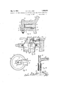
- Figure 1 is a view in sectional side elevation of apparatus constructed and arranged in accordance with the present invention.
- Figure 2 is a view in side elevation of the kettle.
- Figure 3 is a view in plan.
- Figure 4 is a view in sectional side elevation taken on the dotted line 1-4 of Figure 1 and is drawn to a larger scale.
- Figure 5 is a fragmentary view illustrating the construction of the jointbetween sections of the vessel and is drawn to a larger scale.
- Figure 6 is aview in sectional elevation of portion of the kettle and illustrates the action of the trap provided in the inflow launder.
- Figure 7 is a view in plan of an alternative kettle having the inflow and outflow launders arranged side by side.
- Figure 8 is a sectional detail view of the discharge pipe and spout.
- the reference numeral 1O oesignatcs the lower section of a vessel enclosed by suitable brickwork structure 10, and which may be constructed of cast iron and provided at its lower end with integral webs 11 by means of which it may be mounted on a suitable foundation.
- the said lower section of the kettle preferably converges towards its lower end as in dicated in the dra ings and is provided at its upper end with a circumferential flange 12 which is adapted to be connected to the adjacent flange 13 at the lower end of the upper section 14 of the kettle.
- the upper section 14 may be of conical formation and provided at its upper end with an opening 15 of relatively small diameter.
- the flanges 12 and 13 of the lower and upper sections respectively of the kettle are adapted to be connected by means of an interposed ring 16 of channel cross section which may consist of upper and lower annular plates or rings 17 disposed in contact with the flanges on the upper and lower sectionsof the kettle and welded near their outer ends to a vertical ring 18 as clearly indicated in Figure 5.
- annular plates or rings 17 are adapted to be welded to the adjacent portions of the flanges 12 and 13, and, in order to effect a satisfactory weld, rings 19 of stepped or dovetailed formation may be embedded in the langes during the moulding thereof, as indicated in flange 12 of Figure 5.
- each of the rings 19 comprises two rectangular bars suitably secured together.
- the flanges are preferably connected by means of a plurality of bolts 20.
- annular spaces between the flanges of the upper and lower sections of the kettle on both sides of the interposed ring are prefer- 1 ably packed with suitable refractory material, such as chamotte 21.
- the upper end of the kettle adjacent to the mouth is provided at one side with an integral launder 22 adapted to accommodate the spout 23 of a vertical discharge pipe 2a which is open at its upper and lower ends and disposed centrally within the kettle.
- the upper end of the discharge pipe extends through the upper end of the kettle as indicated.
- the spout 23 is adapted to be embedded in chamotte as indicated in order to form a liquid tight joint therearound.
- the discharge pipe 24 below the junction of the spout 23 may be reduced in diameter and surrounded by a tubular casing 25, thereby forming an annular space adapted to be filled with heat insulating material 26 such as slag wool.
- a metal rod 27 is dis osed within the said discharge pipe and is provided on its lower end with an angular extension 28.
- the upper end of the rod or bar 27 pro-- j ects from the top of the discharge pipe 24 so a that an attendant by periodically turning the kettle, thus forming a submerged inflow opening 32 (see Figure 4).
- An integral upwardly extending lip 33 is provided adjacent to the inflow opening 32 and on the inner side thereof, same being adapted to function as a trap to prevent the outflow of metal from the upper portion of the kettle when the supply of bullion to be treated is interrupted.
- the molten bullion is continuously delivered to the launder 29 together with the requisite amount of zinc, and passes through the submerged inflow opening 32 to the upper layer of the conjugate solutions in the kettle.
- the column of metal in the kettle is maintained at a decreasing range of temperatures, the upper of which is suflicient for the incorporation of the zinc, whilst the temperature at the lower end of the column is somewhat above the eutectic of the residual bullion.
- the residual bullion continuously passes upwardly through the discharge pipe 24 and flows through the spout 23, due to the head of liquid metal thereabove.
- the enriched upper solution is removed either continuously or intermittently from the top of the kettle.
- the bullion from the lower end of the kettle may be removed by means of a pump or a syphon of ordinary construction, thereby obviating the necessity of employing a lateral discharge spout disposed below the level of the liquid column and passing through the wall of the kettle in the manner illustrated in the drawings.
- the outflow launder 22 may be dispensed with.
- a kettle for the purposes set forth comprising a plurality of sections, a ring of channel cross section connecting adjacent sections, and having the flanges thereof directed inwardly, the inner ends of said flanges being secured to the adjacent portions of the said sections of the kettle.
- a liquid tight joint between the sections comprising a ring of channel cross section having its flanges directed inwardly, the inner edges of the flanges being welded to the adjacent portions of the said sections of the kettle.
- a kettle for the purposes set forth comprising a plurality of sections, circumferential flanges at the adjacent ends of the said sections, channel shaped rings disposed between the sections of the kettle, said rings having their flanges directed inwardly and disposed in contact with the adjacent circumferential flanges on the sections of the, kettle, the inner edges of the flanges of the channel shaped ring being welded to the said circumferential flanges of the kettle sections.
- a kettle according to claim 3 wherein the circumferential flanges on the sections of the kettle extend beyond the outer periphery of the channel shaped ring and are connected by means of bolts or like fastening means.
- a kettle according to claim 3 wherein the channel shaped ring comprises a flat annular plate disposed in contact with each of the opposed circumferential flanges of the sections of the kettle, said plates being welder. to the said flanges at their inner circumferential edges, and a vertical ring welded to the said annular plates near their outer circumferenti al edges.
- a kettle according to claim '1 having at its upper end a threat opening substantia ly smaller in size than the body portion of 1 the kettle.
- a kettle for the purposes set forth having a throat opening at the upper end thereof, an inflow launder near the top of the kettle and a depending baffle in the inflow launder forming an inflow opening com municating with the interior of the kettle and disposed below the working level of liquid therein.
- a kettle according to claim 10 wherein the inflow launder comprises a trough like member formed integrally with the upper section of the kettle.
- a kettle for the purposes set forth com prising a vessel of circular cross-section hav ing a throat opening at its upper end, and a siiilomeri inflow opening near the upper end of the kettle for the delivery of bullion to be treated.
- an outfio r launder disposed adjacent to the upper end of the kettle, a vertical discharge pipe disposed within the kettle, a spout on the discharge pipe and partially disposed within the said outflow launder and refractory packing surrounding the said spout within the outflow launder, and forming a liquid tight joint therewith.
- Apparatus for the purpose set forth com arising a kettle of relatively deep and narrow formation and open its upper end, a vertical discharge pipe in the kettle and open at its upper and lower ends, a radially disposed spout on the discharge pipe adjacent to the upper end of the kettle, a rod passing centrally through the discharge pipe, an angularly disposed portion on the lower end of the rod, and a lining of heat insulating material surrounding a lower portion of the discharge pipe.
- Apparatus for the purposes set forth comprising a kettle of relatively deep and narrow formation, a throat opening at the top of the l ettle, a substantially radially disposed inflow launder near the top of the kettle, a submerged opening between the inflow launder and the interior of the kettle, an outflow launder communicating with the interior of the kettle and disposed at the side of the inflow launder, a vertical discharge pipe in the kettle, a spout on the discharge pipe and partially accommodated within the outflow launder and refractory packing surrounding the spout within the said outflow launder.
- a vertical discharge pipe open at its lower end, a radially extending spout adjacent to the upper end of the kettle, a tubular casing surrounding portion of the discharge pipe below the spout, an annular space between the tubunature.
Landscapes
- Engineering & Computer Science (AREA)
- Chemical & Material Sciences (AREA)
- Manufacturing & Machinery (AREA)
- Materials Engineering (AREA)
- Mechanical Engineering (AREA)
- Metallurgy (AREA)
- Organic Chemistry (AREA)
- Manufacture And Refinement Of Metals (AREA)
Description
May 3, 1932. G. K. WILLIAMS APPARATUS, FOR USE IN THE REFINING OF LEAD BULLION AND SIMILAR OPERATIONS '2 Sheets-Sheet Filed Sept. 9, 1930 y 3, 1932' G. K. WILLIAMS. 1,856,678
APPARATUS FOR USE IN THE REFINING OF LEAD BULLION AND SIMILAR OPERATIONS Filed. Sept. 9, 1930 2 Sheets-Sheet 2 Patented May 3, 1932 TUNETEB stares PATENT 0FFE APPARATUS FOR USE IN THE REFINING OF LEAD BULLION AND SIMILAR OPERATIONS Application filed September 9, 1930, Serial No.
This invention relates to certain improvements in apparatus for use in the refining of lead bullion'and similar operations and refers more especially to apparatus for the refining of lead bullion containing other metals such as copper, gold, silver or mixtures thereof.
Though this invention is herein described as adapted and used for the refining of lead bullion it will be understood that it is also applicable to the treatment of other liquid systems wherein certain constituents or substances (sometimes in the form of impurities) are removed by subjecting the same to differential temperatures.
This invention is especially adapted for the refining of lead bullion by such processes wherein zinc is incorporated with the said bullion for the formation of certain alloys of the said metals with zinc (with or without lead). 7
Examples of such processes are (a) The Parkes process wherein crusts are formed comprising alloys of the said metals with zinc (with or without lead).
(6) The process for the enrichment of the said crusts obtained in the aforesaid Parkes process, consisting in melting the crusts to form conjugate solutions, the upper layer of which comprises an alloy richin the metal or metals (e. g. gold and silver) to be recovered, and the lower layer of which is poorer in said metals, and separating the layers. This process is described in the specification of Australian Patent No. 5681/22.
(0) The process for the refining of bullion wherein a sufficient quantity of zinc is incorporated with the said bullion and the same is maintained at the required temperature for the formation of molten layers of conjugate solutions, the upper layer of which comprises an alloy with zinc or other metal or metals and the lower layer of bullion which, if desired, can be cooled to its eutectic temperature, producing residual bullion relatively low in such metals.
The invention is also applicable tothe operation known as liquation as applied to the crusts formed by the aforesaid Parkes 480,736, and in Australia November 7, 1929.
process in which the said crusts are heated for the removal of excess lead.
In addition, the invention is applicable to the preliminary treatment to which lead bullion is usually subjected for the removal of the major portion of the copper contained therein, wherein the temperature of the liquid bullion is lowered, causing the copper or compounds of copper to separate out due to the decreased solubility thereof in lead at such low temperatures.
The invention relates especially to certain improvements in apparatus described and claimed in the specification of United States Patent No. 1,687,187. v
In the use of the apparatus as described in the aforementioned patent, difiiculty has been experienced in maintaining a liquid tight joint at the flanges where the two portions of the vessel have been connected together. In constructing a vessel in accordance with the aforesaid invention, it was the practice to form the said flanges with a concentric groove within which a circulating water pipe was accommodated with a view to ensuring that any metal entering the said joint is frozen and leakage avoided.
In practice it has been found that, owing to the very severe stresses to which the metal is subjected, due to the maintenance of the bullion in liquid system and the application thereto of differential temperatures, great difficulty has been experienced in maintaining the aforesaid joint liquid tight, and it has been found that the said joint did not permit of movement of the two parts of the vessel to accommodate the same to stresses, and consequently, they are very liable tofracture.
Furthermore, in operating the apparatus in accordance with the aforesaid invention, it has been necessary to maintain the lower end of the delivery spout at a temperature just above the eutectic of the residual bullion, whilst the said spout requires to be maintained at such a temperature as will enable the metal to be maintained liquid therein with a view to ensuring a coniinuousfiow. There is, therefore, a liability of the metal to freeze at the inlet to the said spout, or
Ice
alternatively to form crusts around the entrance thereto.
Instead of having the discharge pipe exterior the said vessel, it has been the practice to accommodate the same within the interior of the vessel, having suitable means for the discharge through the upper partof the kettle. Furthermore, in practice, there is someimes a tendency to form crusts on the sides of the kettle, and during the operation it is necessary to remove these by means of scrapers, forcing them into the interior of the liquid bullion, where they are absorbed in the liquid system. The arrangement of the pipe within the interior of the kettle has r so afforded a surface upon which these crusts are likely to accumulate and difficulty has sometimes been experienced in freeing the said crusts by means of scrapers. When the pipe has been arranged out of the centre as is most convenient for providing a suitable area at the top of the kettle, for the removal of the rich alloys, there has been a. tendency for the said crusts to accumulate in the restricted area of the kettle between the spout and the walls adjacent thereto, such position being inaccessible for the operation of the scraper of the operator.
The object of this invention is to provide certain detailed improvements in the construction of the aforesaid apparatus whereby the disabilities mentioned above will be overcome.
1 accomplish the object of this invention by constructing the vessel in two or more sections provided with flanges, and in interposing between said flanges a ring of channel cross section, having the flanges thereof directed inwardly and welded at their inner ends to adjacent flanges of the sections of the vessel, thus providing a joint permitting of the requisite relative movement whilst, at the area time, being liquid tight.
The flanges are also preferably connected by means of bolts or the like.
Further features of the invention are to provide inflow and outflow launders in the upper section of the vessel or kettle. The inflow launder is provided with adownwardly projecting baffle by means of which a submerged inlet opening is formed and a lip may be provided within the kettle and adjacent the said inflow opening to form a trap for preventing the passage of molten nietal fromv the upper Zone of the kettle to the said 'nflow launder.
Further features of the invention consis in insulating the discharge pipe to minimize crust formation. on the exterior surface there of and in providing an agitating member er:- ten-ding through the said discharge pipe and having a projection on its lower end whereby the 10* er end of the discharge pipe may be kept clear of solid crusts forming adjacent thereto.
1 tne essors Additional features of the invention will be hereinafter fully described.
Having set forth the object and nature of the invention, reference will now be made to the accompanying drawings wherein:
Figure 1 is a view in sectional side elevation of apparatus constructed and arranged in accordance with the present invention.
Figure 2 is a view in side elevation of the kettle.
Figure 3 is a view in plan.
Figure 4 is a view in sectional side elevation taken on the dotted line 1-4 of Figure 1 and is drawn to a larger scale.
Figure 5 is a fragmentary view illustrating the construction of the jointbetween sections of the vessel and is drawn to a larger scale.
Figure 6 is aview in sectional elevation of portion of the kettle and illustrates the action of the trap provided in the inflow launder.
Figure 7 is a view in plan of an alternative kettle having the inflow and outflow launders arranged side by side.
Figure 8 is a sectional detail view of the discharge pipe and spout.
Referring to the drawings, which illustrate apparatus constructed in accordance with the present invention and specially adapted for carrying out the conjugatesolution process referred to above, the reference numeral 1O oesignatcs the lower section of a vessel enclosed by suitable brickwork structure 10, and which may be constructed of cast iron and provided at its lower end with integral webs 11 by means of which it may be mounted on a suitable foundation.
The said lower section of the kettle preferably converges towards its lower end as in dicated in the dra ings and is provided at its upper end with a circumferential flange 12 which is adapted to be connected to the adjacent flange 13 at the lower end of the upper section 14 of the kettle.
The upper section 14: may be of conical formation and provided at its upper end with an opening 15 of relatively small diameter.
The flanges 12 and 13 of the lower and upper sections respectively of the kettle are adapted to be connected by means of an interposed ring 16 of channel cross section which may consist of upper and lower annular plates or rings 17 disposed in contact with the flanges on the upper and lower sectionsof the kettle and welded near their outer ends to a vertical ring 18 as clearly indicated in Figure 5.
The inner ends of the annular plates or rings 17 are adapted to be welded to the adjacent portions of the flanges 12 and 13, and, in order to effect a satisfactory weld, rings 19 of stepped or dovetailed formation may be embedded in the langes during the moulding thereof, as indicated in flange 12 of Figure 5.
In the construction shown in Figure 5, each of the rings 19 comprises two rectangular bars suitably secured together. In addition, the flanges are preferably connected by means of a plurality of bolts 20.
The annular spaces between the flanges of the upper and lower sections of the kettle on both sides of the interposed ring are prefer- 1 ably packed with suitable refractory material, such as chamotte 21.
By constructing the joint between the sections of the kettle as above described, leakage of metal is prevented whilst, at the same time, suflicient relative movement can take place to obviate excessive strains in the vessel due to temperature variations.
The upper end of the kettle adjacent to the mouth is provided at one side with an integral launder 22 adapted to accommodate the spout 23 of a vertical discharge pipe 2a which is open at its upper and lower ends and disposed centrally within the kettle.
The upper end of the discharge pipe extends through the upper end of the kettle as indicated.
The spout 23 is adapted to be embedded in chamotte as indicated in order to form a liquid tight joint therearound.
' The discharge pipe 24 below the junction of the spout 23 may be reduced in diameter and surrounded by a tubular casing 25, thereby forming an annular space adapted to be filled with heat insulating material 26 such as slag wool.
By insulating the discharge pipe in this manner the relatively cool lead passing upwardly through the discharge pipe is prevented from cooling, to any marked extent,
tho bullion in the hotter and upper zones of the kettle, thus minimizing the accumulation of crusts therearound.
F or the purpose of preventing the accumulation of crusts in the bottom portion of the kettle around the lower end of the discharge )ioe 24 a metal rod 27 is dis osed within the said discharge pipe and is provided on its lower end with an angular extension 28.
The upper end of the rod or bar 27 pro-- j ects from the top of the discharge pipe 24 so a that an attendant by periodically turning the kettle, thus forming a submerged inflow opening 32 (see Figure 4).
The use of a submerged inflow opening has the advantage of leaving undisturbed the upper surface of the liquid metal in the kettle,
thus facilitating the removal of the enriched upper solution when the conjugate solution process is being operated, and also obviating the detrimental effects which are produced when incoming bullion disturbs the said surface of the upper solution as with the apparatus described in the aforesaid United States specification No. 1,687,187.
An integral upwardly extending lip 33 is provided adjacent to the inflow opening 32 and on the inner side thereof, same being adapted to function as a trap to prevent the outflow of metal from the upper portion of the kettle when the supply of bullion to be treated is interrupted.
The function of this trap is indicated in Figure 6 wherein it will be seen that the molten bullion 34 in the inflow launder 29 between the submerged opening 32 and the lip 33 serves to prevent the enriched upper conjugate solution 35 from passing into the launder. Thelo-wer conjugate solution is indicated at 36.
In the operation of the continuous conj ugate solution process for the desilverization of lead-i. e. the process (0) referred to above, the molten bullion is continuously delivered to the launder 29 together with the requisite amount of zinc, and passes through the submerged inflow opening 32 to the upper layer of the conjugate solutions in the kettle.
The column of metal in the kettle is maintained at a decreasing range of temperatures, the upper of which is suflicient for the incorporation of the zinc, whilst the temperature at the lower end of the column is somewhat above the eutectic of the residual bullion.
The residual bullion continuously passes upwardly through the discharge pipe 24 and flows through the spout 23, due to the head of liquid metal thereabove.
The enriched upper solution is removed either continuously or intermittently from the top of the kettle.
'When the kettle is to be heated externally ice by means of upper and lower passages 37 and tion chambers (not illustrated) it may be desirable to arrange the inflow and outflow launders 29 and 22 respectively side by side as illustrated in Figures 6 and 7, in order to pro- ,38 respectively communicating with combusvide a minimum-of obstruction to the gases ordinary Parkes process, and likewise, the inflow and outflow launders are not neces sary for this operation.
In a modification of the invention, the bullion from the lower end of the kettle may be removed by means of a pump or a syphon of ordinary construction, thereby obviating the necessity of employing a lateral discharge spout disposed below the level of the liquid column and passing through the wall of the kettle in the manner illustrated in the drawings.
In this case, therefore, the outflow launder 22 may be dispensed with.
I claim:
1. A kettle for the purposes set forth comprising a plurality of sections, a ring of channel cross section connecting adjacent sections, and having the flanges thereof directed inwardly, the inner ends of said flanges being secured to the adjacent portions of the said sections of the kettle.
2. In a kettle for the purposes setforth and consisting of a plurality of sections, a liquid tight joint between the sections comprising a ring of channel cross section having its flanges directed inwardly, the inner edges of the flanges being welded to the adjacent portions of the said sections of the kettle.
8. A kettle for the purposes set forth comprising a plurality of sections, circumferential flanges at the adjacent ends of the said sections, channel shaped rings disposed between the sections of the kettle, said rings having their flanges directed inwardly and disposed in contact with the adjacent circumferential flanges on the sections of the, kettle, the inner edges of the flanges of the channel shaped ring being welded to the said circumferential flanges of the kettle sections.
I. In a kettle according to claim 3, a plurality of bolts connecting the flanges on the adjacent sections of the kettle.
5. A kettle according to claim 3 wherein the circumferential flanges on the sections of the kettle extend beyond the outer periphery of the channel shaped ring and are connected by means of bolts or like fastening means.
6. A kettle according to claim 3 wherein the channel shaped ring comprises a flat annular plate disposed in contact with each of the opposed circumferential flanges of the sections of the kettle, said plates being welder. to the said flanges at their inner circumferential edges, and a vertical ring welded to the said annular plates near their outer circumferenti al edges.
7. A kettle according to claim 3 wherein the joint between the flanges of the sections of the kettle is packed with suitable refractory material.
8. A kettle according to claim '1 having at its upper end a threat opening substantia ly smaller in size than the body portion of 1 the kettle.
9. In a kettle according to claim 1 a submerged inflow opening for bullion passing thereto.
10. A kettle for the purposes set forth having a throat opening at the upper end thereof, an inflow launder near the top of the kettle and a depending baffle in the inflow launder forming an inflow opening com municating with the interior of the kettle and disposed below the working level of liquid therein.
11. A kettle according to claim 10 wherein the inflow launder comprises a trough like member formed integrally with the upper section of the kettle.
12. A kettle according to claim 10 wherein an upwardly projecting lip is provided in the upper portion of the kettle adjacent to the submerged inflow passage of the said launder, the upper edge of said lip being above the level of the top of the said submerged inilow opening.
13. A kettle for the purposes set forth com prising a vessel of circular cross-section hav ing a throat opening at its upper end, and a siiilomeri inflow opening near the upper end of the kettle for the delivery of bullion to be treated.
14-. In a kettle according to claim 10, an outfio r launder disposed adjacent to the upper end of the kettle, a vertical discharge pipe disposed within the kettle, a spout on the discharge pipe and partially disposed within the said outflow launder and refractory packing surrounding the said spout within the outflow launder, and forming a liquid tight joint therewith.
15. Apparatus for the purpose set forth com arising a kettle of relatively deep and narrow formation and open its upper end, a vertical discharge pipe in the kettle and open at its upper and lower ends, a radially disposed spout on the discharge pipe adjacent to the upper end of the kettle, a rod passing centrally through the discharge pipe, an angularly disposed portion on the lower end of the rod, and a lining of heat insulating material surrounding a lower portion of the discharge pipe.
16. Apparatus for the purposes set forth comprising a kettle of relatively deep and narrow formation, a throat opening at the top of the l ettle, a substantially radially disposed inflow launder near the top of the kettle, a submerged opening between the inflow launder and the interior of the kettle, an outflow launder communicating with the interior of the kettle and disposed at the side of the inflow launder, a vertical discharge pipe in the kettle, a spout on the discharge pipe and partially accommodated within the outflow launder and refractory packing surrounding the spout within the said outflow launder.
17. In a kettleaccording toclaim 10, a vertical discharge pipe open at its lower end, a
radially extending spout adjacent to the upper end of the discharge pipe and a lining of heat insulating material around the lower portion of the said discharge pipe.
18. In a kettle according to claim 10, a vertical discharge pipe open at its lower end, a radially extending spout adjacent to the upper end of the kettle, a tubular casing surrounding portion of the discharge pipe below the spout, an annular space between the tubunature.
GEORGE KENNETH WILLIAMS.
Applications Claiming Priority (1)
| Application Number | Priority Date | Filing Date | Title |
|---|---|---|---|
| AU1856678X | 1929-11-07 |
Publications (1)
| Publication Number | Publication Date |
|---|---|
| US1856678A true US1856678A (en) | 1932-05-03 |
Family
ID=3837702
Family Applications (1)
| Application Number | Title | Priority Date | Filing Date |
|---|---|---|---|
| US480736A Expired - Lifetime US1856678A (en) | 1929-11-07 | 1930-09-09 | Apparatus for use in the refining of lead bullion and similar operations |
Country Status (1)
| Country | Link |
|---|---|
| US (1) | US1856678A (en) |
Cited By (2)
| Publication number | Priority date | Publication date | Assignee | Title |
|---|---|---|---|---|
| US2829960A (en) * | 1954-01-18 | 1958-04-08 | Henry J Kaiser Company | Method and metallurgical device for the refining of steel |
| FR2321548A1 (en) * | 1975-08-19 | 1977-03-18 | Broken Hill Ass Smelter | LEAD DEBISMUTHISATION |
-
1930
- 1930-09-09 US US480736A patent/US1856678A/en not_active Expired - Lifetime
Cited By (3)
| Publication number | Priority date | Publication date | Assignee | Title |
|---|---|---|---|---|
| US2829960A (en) * | 1954-01-18 | 1958-04-08 | Henry J Kaiser Company | Method and metallurgical device for the refining of steel |
| FR2321548A1 (en) * | 1975-08-19 | 1977-03-18 | Broken Hill Ass Smelter | LEAD DEBISMUTHISATION |
| US4042228A (en) * | 1975-08-19 | 1977-08-16 | The Broken Hill Associated Smelters Proprietary Limited | Apparatus for debismuthising lead |
Similar Documents
| Publication | Publication Date | Title |
|---|---|---|
| SU1232149A3 (en) | Immersion capsule for feeding evaporating additives into iron and steel melt | |
| US2130202A (en) | Continuously casting pipe | |
| US3934755A (en) | Method and device for preventing slag from escaping when emptying a pouring vessel | |
| US1856678A (en) | Apparatus for use in the refining of lead bullion and similar operations | |
| US2955333A (en) | Electric arc furnaces | |
| US1184523A (en) | Process for casting molten materials. | |
| US3448790A (en) | Molds for electroslag refining | |
| US3066364A (en) | Pouring technique for continuous casting | |
| JPH11314921A (en) | Sunk glass transportation throat | |
| SU532323A3 (en) | Installation of continuous metal casting | |
| EP0209593A1 (en) | CONTINUOUS CASTING METHOD. | |
| US2191337A (en) | Melting apparatus | |
| US612134A (en) | Toussaint levoz | |
| US1687187A (en) | Apparatus for use in refining of lead bullion and similar operations | |
| US2756988A (en) | Transfer device for conveying molten metal | |
| JPS60255246A (en) | Casting device for tundish in continuous casting device | |
| US1024722A (en) | Process and apparatus for casting ingots. | |
| US666373A (en) | Skimming-trough. | |
| US2676011A (en) | Construction for the tap holes of open-hearth furnaces | |
| SU381250A1 (en) | Crystallizer | |
| SU473365A3 (en) | Device for removing non-metallic inclusions from the melt | |
| US1375589A (en) | Appliance for casting metal ingots into molds | |
| US2303139A (en) | Method of and apparatus for centrifugally degasifying molten metal | |
| US1777659A (en) | Method of forming zinc ingots for working | |
| RU2728142C1 (en) | Melting-filling crucible with automatic discharge of melt through channel of siphon type |