US1856664A - Faucet - Google Patents
Faucet Download PDFInfo
- Publication number
- US1856664A US1856664A US516181A US51618131A US1856664A US 1856664 A US1856664 A US 1856664A US 516181 A US516181 A US 516181A US 51618131 A US51618131 A US 51618131A US 1856664 A US1856664 A US 1856664A
- Authority
- US
- United States
- Prior art keywords
- rod
- faucet
- cylinder
- disc
- casing
- Prior art date
- Legal status (The legal status is an assumption and is not a legal conclusion. Google has not performed a legal analysis and makes no representation as to the accuracy of the status listed.)
- Expired - Lifetime
Links
- XLYOFNOQVPJJNP-UHFFFAOYSA-N water Substances O XLYOFNOQVPJJNP-UHFFFAOYSA-N 0.000 description 11
- 230000000979 retarding effect Effects 0.000 description 6
- 239000004744 fabric Substances 0.000 description 5
- 230000000994 depressogenic effect Effects 0.000 description 4
- 238000010276 construction Methods 0.000 description 3
- 239000002184 metal Substances 0.000 description 3
- 238000012856 packing Methods 0.000 description 3
- 238000005192 partition Methods 0.000 description 2
- 241000606643 Anaplasma centrale Species 0.000 description 1
- 230000001276 controlling effect Effects 0.000 description 1
- 238000012986 modification Methods 0.000 description 1
- 230000004048 modification Effects 0.000 description 1
- 230000001105 regulatory effect Effects 0.000 description 1
Images

Classifications
-
- F—MECHANICAL ENGINEERING; LIGHTING; HEATING; WEAPONS; BLASTING
- F16—ENGINEERING ELEMENTS AND UNITS; GENERAL MEASURES FOR PRODUCING AND MAINTAINING EFFECTIVE FUNCTIONING OF MACHINES OR INSTALLATIONS; THERMAL INSULATION IN GENERAL
- F16K—VALVES; TAPS; COCKS; ACTUATING-FLOATS; DEVICES FOR VENTING OR AERATING
- F16K21/00—Fluid-delivery valves, e.g. self-closing valves
- F16K21/04—Self-closing valves, i.e. closing automatically after operation
- F16K21/06—Self-closing valves, i.e. closing automatically after operation in which the closing movement, either retarded or not, starts immediately after opening
- F16K21/10—Self-closing valves, i.e. closing automatically after operation in which the closing movement, either retarded or not, starts immediately after opening with hydraulic brake cylinder acting on the closure member
-
- Y—GENERAL TAGGING OF NEW TECHNOLOGICAL DEVELOPMENTS; GENERAL TAGGING OF CROSS-SECTIONAL TECHNOLOGIES SPANNING OVER SEVERAL SECTIONS OF THE IPC; TECHNICAL SUBJECTS COVERED BY FORMER USPC CROSS-REFERENCE ART COLLECTIONS [XRACs] AND DIGESTS
- Y10—TECHNICAL SUBJECTS COVERED BY FORMER USPC
- Y10T—TECHNICAL SUBJECTS COVERED BY FORMER US CLASSIFICATION
- Y10T137/00—Fluid handling
- Y10T137/7504—Removable valve head and seat unit
- Y10T137/7668—Retained by bonnet or closure
Definitions
- This invention relatesto improvements in faucets and, more especially, self-closing faucets.
- Another feature of my invention is the 10, provision of a faucet of thecharacter referred to, in which all the operating parts, including the seat, can be easily and quickly removed for repair, replacement or other purposes.
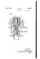
- Figure 1 is a view in side elevation;
- Fig. 2 is a top plan view;
- Fig. 3 is a View taken as indicated by the line 3 of Fig 2;
- Fig. 4 is a view taken as indicated by the line 3 of Fig 2;
- Fig. 5 is a top plan view of one of the discs used for controlling the speed of closing
- Fig. 6 is a view similar to Fig. 4, showing a modified form
- Fig. 7 is a fragmentary vertical sectional view of the '25 operating parts showing the same removed from the faucet
- Fig. 5 is a top plan view of one of the discs used for controlling the speed of closing
- Fig. 6 is a view similar to Fig. 4, showing a modified form
- FIG. 6 is a view similar to Fig. 6 showing amodiiied form.
- 10 indicates a suitable casing with an inlet opening 11 and a discharge spout 12.
- the casing is preferably somewhat enlarged to provide the chamber 13, the latter being open at the top, said opening being surrounded by the upstanding threaded rim 14.
- Numeral 15 indicates a cap threaded onto the rim 14 provided with a. central opening through which the operating pin 16 extends.
- Numeral 17 indicates a cap threaded onto the upper end of the pin and adapted to be depressed to open the faucet.
- Packing 18 is provided to make a water-tight joint where the pin 16 extends through the cap 15, said packing being held in position by awasher 19.
- Numeral 20 indicates a gasket or washer to make a tight joint between the rim 14 and cap 15.
- Reference numeral 21 indicates a removable barrel or cylinder, open at the bottom to form an inlet 22 and provided with radial outlet apertures 23 near the bottom.
- the lower end of the cylinder 21 carries a. removable seat 24 adapted to be held in watertight contact with the rim 11 surrounding the upper end of the inlet opening 11, when the cap 15 is screwed into place.
- the cylinder 21 is provided with an apertured partition or diaphragm 25 through which extends the rod 26 carrying the valve 27 on its lower end, said valve adapted to seat against the lower edge 24 of the seat 24 to close the valve.
- the rod 26 is yieldingly urged upwardly by the spring 28 lying above the partition 25, the rod being provided at its upper end with an enlargement 26? above the spring.
- Numeral 29 indicates a cap over the upper end of the rod 26. Lying on the cap 29 is a plurality (here shown as three) of fabric discs 30 and on top of them preferably a metal disc 31. One of the discs 30 is shown in Fig. 5. These discs fit fairly tight in the cylinder 21 but not tight enough to prevent downward manual pressure on the cap 17 from moving them downwardly to open the faucet.
- F ig..4 the spring 28 is compressed and the upper edge of the disc 31 is below the holes 32 in the cylinder 21. lVhen in this position,v water will pass through the small space 33 surrounding the cylinder 21, enter the holes 32 and fill the space 34 in the cylinder above the discs 30 and 31.
- the metal disc 31 is preferably made somewhat smaller than the fabric discs 30, its primary function being to take the thrust of the lower end of the rod 16. The rate of closing can be varied as desired by changing the number, size and character of the discs 30.
- the rod 126 correspond.
- Thecap 129.- resembles the cap 29, except that it isprovided with'a central boss. 140-. in whichis mounted the screw-141. Instead of using disc washers 30in this construction, there. are-provided circular. rings or washers-130i having; holes to accommodate the boss. 1410 and screw 141.. Above the fabric washers l30isametal Washer 131 adapted to beengagedby the head oflthescrew 1&1. Theboss; 140 is low enough so that the screwll may be screwed down to. push. down the washer 131 to. squeeze the fabric discs 1301' In this: manner, the fabric. discsrnay be more or less-squeezed and the friction thus regulated to adj-nstthe speed of. closing-of thev faucet.
- This retarding-piston229 is-integrally formed on the lower end of thestem-216 'whichresembl'es the. stem 16. of Fig. 3 and carries. on its upper end. the pushbntton or cap 17 top of; theflpi ston 229,,there is. provided acup washer 230 operating in the cylinder 221. This. cup washer is held in placeby a metal Washer 230? above it which, in turn isheld down by the-nut 230" threadedaonthe enlarged portion 216 of thestem 216.
- the cap 215 is similar to the: cap. 15- of Fig.3, but. made somewhat highertorgive room for thepaclc ing.
- the rod- 226 correspondingto the rods 26 and 126 of the other forms, is provided at its upper end with a screw 226* very similar to the screw 126 of Fig. .6, except that-the head thereof is made somewhat higher and provided with a beveled portion- 226 adapted to seal the lower end of the-opening-QIGP provided in the a mafia. an...
- a removable cylinder in said casing carrying a seat held against. the rim of. the inlet. opening, the lower. end of said. cylinder being, provided with. an. inlet opening registering with, the inlet opening in: the, casing, and a. dischargeopening communicating with the discharge. opening in the casing; a rod slidably monntedin said cylindercarrying a. valve onits lower end. below said. seat; an adjusting screw in the.- upper endofsaid rod means/for. yielding-1y urging said rod, upwardly to causesaid valve. to-rest on. said seat to closethe. faucet, saidmeans including a. spiral spring surroundlng said rod lying under the: head of; said adjusting screw; manually operablemeans for pressing therod; downwardly to open thefaucet; and
- said means including a disc in the cylinder adaptedto be moved with the rod, said disc adapted to. trap water in the cylinder above the disc whendepressed, water so trapped being permitted to escape slowly to permit upward movement of the disc at a retarded speed.
- a faucet of the, character described including; a casing with an inlet opening and a discharge opening; a removable cylinder in said casing carryinga seat held against the rim of the inlet opening, the lowerend of said cylinder being providedw-ith an inlet opening registering with the inlet opening in the casing, and a discharge opening connnunicating with the discharge opening in the casing a rod slidably mounted in.
- said cylinder carrying a valve on its lower end below said seat; means for yieldingly urging said r'od upwardly to causesaid valveto'rest on said seat to close the faucet; manually able means for pressing the rod downwardly operable means for pressing the rod downto open the faucet.
- said means including a disc in the cylinder adapted to be moved with the rod, said disc adapted to trap water in the cylinder above the disc when depressed, water so trapped being permitted to escape slowly to permit upward movement of the disc at a retarded speed; and means for adjusting the frictional resistance of said disc in said cylinder.
- a faucet as claimed in claim 2 provided with a plurality of discs in the cylinder.
- a faucet of the character described including; a casing with an inlet opening and a discharge opening; a removable cylinder in said casing carrying a seat held against the rim of the inlet opening. the lower end of said cylinder being provided with an inlet opening registering with the inlet opening in the casing. and a discharge opening communicating with the discharge opening in the casing; a rod slidably mounted in said cylinder carrying a valve on its lower end below said seat: means for yieldin ly urging said rod upwardly to cause said valve to rest on said seat to close the faucet: manually operable means for pressing the rod downwardly to open the faucet: means for retarding the upward movement of said rod.
- said means including a disc in the c linder adapted to be moved with the rod said disc adapted to trap water in the cylinder above the disc when depressed, water so trapped being permitted to escape slowlv to permit upward movement of the disc at a retarded s eed: and adjustable means for soueezing said d scto var the frictional resistance of the disc in the cylinder.
- a faucet of the character described including: a casing with an inlet opening and a discharge opening: a removable cylinder in said casing carrying a seat held against the rim of the inlet openin the lower end of said. cylinder being provided with an inlet opening registering with the inlet opening in the casing.
Landscapes
- Engineering & Computer Science (AREA)
- General Engineering & Computer Science (AREA)
- Mechanical Engineering (AREA)
- Self-Closing Valves And Venting Or Aerating Valves (AREA)
Description
y 3, 1932- H. s. STEEN 1,856,664
FAUCET Filed Feb. 16, 1931 2 Sheets-Sheet l I; IJHIMIIIIIIIIII [III I 1512/ 2 Ja -3. 150/ h ngar.
"9 jravffgam \Z gz maym. a" r Patented May 3, 1932 UNETED STATES PATENT OFFlCE i HARRY S. STEEN, OF CHICAGO, ILLINOIS, ASSIGNOR TO THE CHICAGO FAUCET COT/[- PANY, OF CHICAGO, ILLINOIS, A CORPORATION OF ILLINOIS FAUCET Application filed February 16; 1931. Serial No. 516,181.
This invention relatesto improvements in faucets and, more especially, self-closing faucets.
Among the features of my invention is 65} the provision of improved means'for retarding the closing of the faucet. Means are also providing for easily varying the'rate of closing.
Another feature of my invention is the 10, provision of a faucet of thecharacter referred to, in which all the operating parts, including the seat, can be easily and quickly removed for repair, replacement or other purposes.
\ Other features and advantages of my invention will appear more fully as I proceed with my specification.
In those forms of devices embodying the features of my invention shown in the ac- 20 companying dra-wings Figure 1 is a view in side elevation; Fig. 2 is a top plan view; Fig. 3 is a View taken as indicated by the line 3 of Fig 2; Fig. 4
. is a fragmentary vertical sectional view of the '25 operating parts showing the same removed from the faucet; Fig. 5 is a top plan view of one of the discs used for controlling the speed of closing; Fig. 6 is a view similar to Fig. 4, showing a modified form; and Fig. 7
is a view similar to Fig. 6 showing amodiiied form.
As shown in the drawings, 10 indicates a suitable casing with an inlet opening 11 and a discharge spout 12. At the juncture of 3 the spout and theinlet the casing is preferably somewhat enlarged to provide the chamber 13, the latter being open at the top, said opening being surrounded by the upstanding threaded rim 14.
Numeral 15 indicates a cap threaded onto the rim 14 provided with a. central opening through which the operating pin 16 extends. Numeral 17 indicates a cap threaded onto the upper end of the pin and adapted to be depressed to open the faucet. Packing 18 is provided to make a water-tight joint where the pin 16 extends through the cap 15, said packing being held in position by awasher 19. Numeral 20 indicates a gasket or washer to make a tight joint between the rim 14 and cap 15.
Just above the holes 23, the cylinder 21 is provided with an apertured partition or diaphragm 25 through which extends the rod 26 carrying the valve 27 on its lower end, said valve adapted to seat against the lower edge 24 of the seat 24 to close the valve. The rod 26 is yieldingly urged upwardly by the spring 28 lying above the partition 25, the rod being provided at its upper end with an enlargement 26? above the spring.
When pressure on the cap 17 is released, the spring 28 urges the rod 26 upwardly to close the faucet; but as soon as the discs 30, 31 pass the holes 32, water will be trapped in the space 34 andupward movement of the rod 26 will be retarded. The closing of the faucet will then be continued only as rapidly as per- 9 mitted by leakage or escape of water by the discs 30, 31 out of the shrinking space 34. The metal disc 31 is preferably made somewhat smaller than the fabric discs 30, its primary function being to take the thrust of the lower end of the rod 16. The rate of closing can be varied as desired by changing the number, size and character of the discs 30.
shown resemble, in construction and opera-- tion, the parts shown in Fig. 4L, with. the following exceptions. The rod 126, correspond.
ing. to the. rod 26', is: provided attitsup per end with an adjusting screw 126 -insteadof the head26 and. the spring 28.lies under this head. This adjusting screw permits-an. a.d.-
j ustment of the travel of the-piston. Thecap 129.- resembles the cap 29, except that it isprovided with'a central boss. 140-. in whichis mounted the screw-141. Instead of using disc washers 30in this construction, there. are-provided circular. rings or washers-130i having; holes to accommodate the boss. 1410 and screw 141.. Above the fabric washers l30isametal Washer 131 adapted to beengagedby the head oflthescrew 1&1. Theboss; 140 is low enough so that the screwll may be screwed down to. push. down the washer 131 to. squeeze the fabric discs 1301' In this: manner, the fabric. discsrnay be more or less-squeezed and the friction thus regulated to adj-nstthe speed of. closing-of thev faucet.
In the modified form shown in Fig.1 7,.the piston isiattached. tot-he. cap instead of. being carried by the, valve stem. Asfhere shown, the construction-is. similar to those already describedgy with the following exceptions. The retarding piston, indicated by 229; takes the placeof the caps or. retarding pistons,
' indicated by. 29.and. 129. in the? other. forms.
This retarding-piston229 is-integrally formed on the lower end of thestem-216 'whichresembl'es the. stem 16. of Fig. 3 and carries. on its upper end. the pushbntton or cap 17 top of; theflpi ston 229,,there is. provided acup washer 230 operating in the cylinder 221. This. cup washer is held in placeby a metal Washer 230? above it which, in turn isheld down by the-nut 230" threadedaonthe enlarged portion 216 of thestem 216. The cap 215 is similar to the: cap. 15- of Fig.3, but. made somewhat highertorgive room for thepaclc ing. 2-18 around the stem 216, said packing adapted to beurged downwardly by the washcr 218 and the spring-218 above it. The rod- 226 correspondingto the rods 26 and 126 of the other forms, is provided at its upper end with a screw 226* very similar to the screw 126 of Fig. .6, except that-the head thereof is made somewhat higher and provided with a beveled portion- 226 adapted to seal the lower end of the-opening-QIGP provided in the a mafia. an...
. the piston itself.
' While. I have shown and described certain embodiments of my invention, it is to be understeod-.that= it is capable of many' modifications. Ghanges ;.therefore, in the. construction and arrangement may be made. without'departing from the. spirit and scope of the invention as disclosed in theappendedclaims, in which. it is my intentionto claim. all novelty inherent in my invention as broadly as. per.- missible, in View of the prior art.
WVhatI regard as'new, and desire, to secure by Letters Patent, is i 1. A. faucet of the character described,
cluding yacasingwith aninlet opening and a discharge opening; a removable cylinder in said casing carrying a seat held against. the rim of. the inlet. opening, the lower. end of said. cylinder being, provided with. an. inlet opening registering with, the inlet opening in: the, casing, and a. dischargeopening communicating with the discharge. opening in the casing; a rod slidably monntedin said cylindercarrying a. valve onits lower end. below said. seat; an adjusting screw in the.- upper endofsaid rod means/for. yielding-1y urging said rod, upwardly to causesaid valve. to-rest on. said seat to closethe. faucet, saidmeans including a. spiral spring surroundlng said rod lying under the: head of; said adjusting screw; manually operablemeans for pressing therod; downwardly to open thefaucet; and
'means. for retarding the: upward. movement of said rod, said means including a disc in the cylinder adaptedto be moved with the rod, said disc adapted to. trap water in the cylinder above the disc whendepressed, water so trapped being permitted to escape slowly to permit upward movement of the disc at a retarded speed.
2; A faucet of the, character described, including; a casing with an inlet opening and a discharge opening; a removable cylinder in said casing carryinga seat held against the rim of the inlet opening, the lowerend of said cylinder being providedw-ith an inlet opening registering with the inlet opening in the casing, and a discharge opening connnunicating with the discharge opening in the casing a rod slidably mounted in. said cylinder carrying a valve on its lower end below said seat; means for yieldingly urging said r'od upwardly to causesaid valveto'rest on said seat to close the faucet; manually able means for pressing the rod downwardly operable means for pressing the rod downto open the faucet.
wardly to open the faucet; means for re- In witness whereof, I have hereunto set my tarding the upward movement of said rod, and t is 12 h day f ebruary, 1931.
said means including a disc in the cylinder adapted to be moved with the rod, said disc adapted to trap water in the cylinder above the disc when depressed, water so trapped being permitted to escape slowly to permit upward movement of the disc at a retarded speed; and means for adjusting the frictional resistance of said disc in said cylinder.
3. A faucet as claimed in claim 2, provided with a plurality of discs in the cylinder.
4. A faucet of the character described, including; a casing with an inlet opening and a discharge opening; a removable cylinder in said casing carrying a seat held against the rim of the inlet opening. the lower end of said cylinder being provided with an inlet opening registering with the inlet opening in the casing. and a discharge opening communicating with the discharge opening in the casing; a rod slidably mounted in said cylinder carrying a valve on its lower end below said seat: means for yieldin ly urging said rod upwardly to cause said valve to rest on said seat to close the faucet: manually operable means for pressing the rod downwardly to open the faucet: means for retarding the upward movement of said rod. said means including a disc in the c linder adapted to be moved with the rod said disc adapted to trap water in the cylinder above the disc when depressed, water so trapped being permitted to escape slowlv to permit upward movement of the disc at a retarded s eed: and adjustable means for soueezing said d scto var the frictional resistance of the disc in the cylinder.
5. A faucet of the character described. including: a casing with an inlet opening and a discharge opening: a removable cylinder in said casing carrying a seat held against the rim of the inlet openin the lower end of said. cylinder being provided with an inlet opening registering with the inlet opening in the casing. and a discharge opening communicating with the discharge opening in the casing; a rod slidably mounted in said cvlinder carrying a valve on its lower end below said seat; means for yieldingly urging said rod upwardly to cause said valve to rest on said seat to close the faucet; manually oper able means for pressing the rod downwardly to open the faucet; and means for retarding the upward movement of said rod, said means including a disc in the cylinder adapted to be moved with the rod, said disc adapted to trap water in the cylinder above the disc when depressed, water so trapped being permitted to escape slowly to permit upward movement of the disc at a retarded speed, said disc being carried by the manually oper- HARRY S. STEEN,
Priority Applications (1)
| Application Number | Priority Date | Filing Date | Title |
|---|---|---|---|
| US516181A US1856664A (en) | 1931-02-16 | 1931-02-16 | Faucet |
Applications Claiming Priority (1)
| Application Number | Priority Date | Filing Date | Title |
|---|---|---|---|
| US516181A US1856664A (en) | 1931-02-16 | 1931-02-16 | Faucet |
Publications (1)
| Publication Number | Publication Date |
|---|---|
| US1856664A true US1856664A (en) | 1932-05-03 |
Family
ID=24054479
Family Applications (1)
| Application Number | Title | Priority Date | Filing Date |
|---|---|---|---|
| US516181A Expired - Lifetime US1856664A (en) | 1931-02-16 | 1931-02-16 | Faucet |
Country Status (1)
| Country | Link |
|---|---|
| US (1) | US1856664A (en) |
Cited By (11)
| Publication number | Priority date | Publication date | Assignee | Title |
|---|---|---|---|---|
| US2481262A (en) * | 1945-11-28 | 1949-09-06 | Trompeter David | Valve for dispensers |
| US2561559A (en) * | 1945-07-26 | 1951-07-24 | Chicago Faucet Company | Faucet unit |
| US2710736A (en) * | 1951-06-20 | 1955-06-14 | Sloan Valve Co | Self-closing faucets |
| US2816569A (en) * | 1954-09-28 | 1957-12-17 | William T Heyer | Replacement valve stem assembly for globe and faucet valves |
| US2963259A (en) * | 1957-09-09 | 1960-12-06 | William T Heyer | Metering valve |
| US4305423A (en) * | 1978-06-28 | 1981-12-15 | H. Adler Associates, Inc. | Combination stop and pressure reducing valve |
| US4313466A (en) * | 1980-04-23 | 1982-02-02 | H. E. Rudge And Company Limited | Valve for drinking fountains |
| FR2509007A1 (en) * | 1981-07-03 | 1983-01-07 | Presto Robinets Sa | TAP HEAD, COMPRISING A TIMING DEVICE, ADAPTABLE TO BASES RECEIVING ORDINARY HEADS |
| US4723570A (en) * | 1985-12-24 | 1988-02-09 | Kabushiki Kaisha Naniwa Seisakusho | Water Faucet |
| US4729543A (en) * | 1985-08-01 | 1988-03-08 | Shaham Y. Aricha & Sons Limited | Valve |
| US20070131288A1 (en) * | 2005-12-14 | 2007-06-14 | T & S Brass And Bronze Works, Inc. | Valve and valve cartridge |
-
1931
- 1931-02-16 US US516181A patent/US1856664A/en not_active Expired - Lifetime
Cited By (12)
| Publication number | Priority date | Publication date | Assignee | Title |
|---|---|---|---|---|
| US2561559A (en) * | 1945-07-26 | 1951-07-24 | Chicago Faucet Company | Faucet unit |
| US2481262A (en) * | 1945-11-28 | 1949-09-06 | Trompeter David | Valve for dispensers |
| US2710736A (en) * | 1951-06-20 | 1955-06-14 | Sloan Valve Co | Self-closing faucets |
| US2816569A (en) * | 1954-09-28 | 1957-12-17 | William T Heyer | Replacement valve stem assembly for globe and faucet valves |
| US2963259A (en) * | 1957-09-09 | 1960-12-06 | William T Heyer | Metering valve |
| US4305423A (en) * | 1978-06-28 | 1981-12-15 | H. Adler Associates, Inc. | Combination stop and pressure reducing valve |
| US4313466A (en) * | 1980-04-23 | 1982-02-02 | H. E. Rudge And Company Limited | Valve for drinking fountains |
| FR2509007A1 (en) * | 1981-07-03 | 1983-01-07 | Presto Robinets Sa | TAP HEAD, COMPRISING A TIMING DEVICE, ADAPTABLE TO BASES RECEIVING ORDINARY HEADS |
| US4729543A (en) * | 1985-08-01 | 1988-03-08 | Shaham Y. Aricha & Sons Limited | Valve |
| US4723570A (en) * | 1985-12-24 | 1988-02-09 | Kabushiki Kaisha Naniwa Seisakusho | Water Faucet |
| US20070131288A1 (en) * | 2005-12-14 | 2007-06-14 | T & S Brass And Bronze Works, Inc. | Valve and valve cartridge |
| US7306005B2 (en) * | 2005-12-14 | 2007-12-11 | T&S Brass And Bronze Works, Inc. | Valve and valve cartridge |
Similar Documents
| Publication | Publication Date | Title |
|---|---|---|
| US1856664A (en) | Faucet | |
| US1501331A (en) | Flushing device | |
| US1518942A (en) | Flushing valve | |
| US2791235A (en) | Ball cock valve | |
| US2620826A (en) | Flushing valve | |
| US2252923A (en) | Valve | |
| US4295488A (en) | Diaphragm and ball valve | |
| US1964921A (en) | Water-supply cock | |
| US2869570A (en) | Air line automatic drain valve | |
| US3318323A (en) | Automatic drain valves | |
| US2988110A (en) | Faucet | |
| US2060622A (en) | Captive receptacle cap | |
| US2324946A (en) | Retarded self-closing faucet | |
| US1396501A (en) | Flushing-valve | |
| US2023560A (en) | Faucet or valve | |
| US1171085A (en) | Flushometer. | |
| US2635621A (en) | Frostproof hydrant | |
| US2069364A (en) | Valve | |
| US1132570A (en) | Flush-valve. | |
| US1547398A (en) | Operating valve for hydraulic presses | |
| US2730354A (en) | Hydraulic interval timer | |
| US2815040A (en) | Pressure relief valve | |
| US2058868A (en) | Valve | |
| US2372729A (en) | Automatic valve | |
| US1651689A (en) | Pressure-operated valve |