US1856637A - Casket-transferring device - Google Patents
Casket-transferring device Download PDFInfo
- Publication number
- US1856637A US1856637A US456589A US45658930A US1856637A US 1856637 A US1856637 A US 1856637A US 456589 A US456589 A US 456589A US 45658930 A US45658930 A US 45658930A US 1856637 A US1856637 A US 1856637A
- Authority
- US
- United States
- Prior art keywords
- bar
- legs
- heads
- casket
- central section
- Prior art date
- Legal status (The legal status is an assumption and is not a legal conclusion. Google has not performed a legal analysis and makes no representation as to the accuracy of the status listed.)
- Expired - Lifetime
Links
- PXHVJJICTQNCMI-UHFFFAOYSA-N Nickel Chemical compound [Ni] PXHVJJICTQNCMI-UHFFFAOYSA-N 0.000 description 2
- 229910052759 nickel Inorganic materials 0.000 description 1
- 238000004904 shortening Methods 0.000 description 1
Images

Classifications
-
- B—PERFORMING OPERATIONS; TRANSPORTING
- B65—CONVEYING; PACKING; STORING; HANDLING THIN OR FILAMENTARY MATERIAL
- B65G—TRANSPORT OR STORAGE DEVICES, e.g. CONVEYORS FOR LOADING OR TIPPING, SHOP CONVEYOR SYSTEMS OR PNEUMATIC TUBE CONVEYORS
- B65G13/00—Roller-ways
- B65G13/11—Roller frames
- B65G13/12—Roller frames adjustable
Definitions
- This invention relates to a portable conveyor or transfer device for supporting caskets while the latter are being passed through doorways or windows.
- I provide a bar which is extensible and adapted to extend between the sides of a doorway or window frame and which is provided with rollers upon which the casket rides, and to the ends of this bar are pivotally secured channeled legs adapted to stand in upright position and support the bar in a doorway, or to fold under the bar and support it when the device is placed on a window Sill.
- the bar is provided with heads at its ends which fit into the channeled legs and the bar may be connected to the legs at various points in their lengths by removable pivot pins which pass through holes in the legs and holes in the heads.
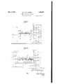
- Fig. 1 is a front elevation of the device, as arranged in a doorway;
- Fig. 2 is a similar view of the device, as arranged on a window sill;
- Fig. 3 is a central longitudinal section through the bar and through the legs, the latter being unfolded as for use in a doorway'
- Fig. 4 is a top plan view of the device with the legs folded;
- Fig. 5 is a side elevation of the device with the legs folded, the latter being shown in central longitudinal section;
- Fig. 6 is a section on the line 66 of Fig. 3;
- Fig. 7 is a section on the line.77 of Fig. 4:.
- A indicates an extensible bar
- B, B indicate the legs of the conveyor.
- the bar is composed of a central section a and two end sections a and 41?.
- the central section is cylindrical and V has a knurled portion 1, which may be readily grasped by the hand, and oppositely extending portions 2, which are bored inwardly from their ends and internally and oppositely threaded, as indicated at 3.
- the sections a and a are alike, each comprising a threaded rod 4 which fitsinto the threaded bore 3 of the central section and a head 5, which is integral with the rod and projects at right angles to the axis of the rod.
- Cylindrical sleeves 6 surround the parts 2 of the central section and the outer ends of these sleeves are secured by pins 7 to the heads 5, as shown. Rollers 8 are mounted upon the sleeves 6 about midway of the length of the sleeves and these rollers are held in place by collars 9.
- the outer ends 5 of the heads 5 are fiat and at right angles to the axis of the bar, and the heads project laterally beyond the body of the bar, as indicated at 5*.
- the heads are adapted to fit within the channeled legs B and the lateral extension of each head is provided with a perforation to receive a removable pivot pin 10.
- the upper portions of the legs are provided with suitably spaced openings 11, through which the pins lO'may be passed, and by means of these pins and perforations the bar may be supported at any desired height on the legs. Perforations 11 are also provided close to the upper ends of the legs but these are not utilized except when the device is folded, as hereinafter described.
- the pins 10 are inserted through opposite holes 11 in the legs, to support the bar at a suitable height above the floor, and the legs are then placed opposite the sides of the doorway, as shown in Fig. 1, and the central section is then turned by hand until the upper parts of the legs, which are in front of said heads, are forced against the sides of the doorway.
- the forward end is set upon the rollers 8 and the casket is then pushed forwardly to attendants on the outside of the house.
- the transfer or conveying device will be arranged upon a window sill, as shown in Fig. 2.
- the pins are passed through the perforations 11, at theends of the legs, and through the heads of the bar, and the legs are then folded under the bar, as illustrated in Figs. 1, 4: 5 and 7, the leg B folding around the leg B.
- the folded legs are then laid upon a window sill and the extensions 5 of the 'heads 5 support the bar at its-ends.
- the I heads 5 By turning'the central section of the bar the I heads 5 will be forced outwardly against the sides of the window frame and the device Will be held securely in position.
- the casket may then be placed on the rollers and pushed through the Window to the attendantson the outside of the house.
- a casket transferring device comprising an extensible sectional bar having heads atits ends, rollers j ournaled on the bar, and channeled legs, said heads fitting within the channels .of the legs and pivotally connected to the side walls thereof, and said legs adapted to stand at right angles tothe bar and to fold substantially parallel with the bar.
- a casket transferring'device comprising an extensible. sectional bar having heads at its ends, rollers j ournaled on the bar, said heads having: parts projecting at one side of the bar, and channeled legs, said heads fitting within the channels of the legs and pivotthereon and having heads at its ends projecting at one side of the bar, and legs pivotally connected at short distance from their upper ends to said projecting parts of the heads,
- said legs adapted to stand at right angles to the bar and with their upper end portions against the ends of said heads and to fold substantially parallel with the bar.
- a casket transferring device comprising a sectional bar having a central section and twoend sections, the latter having oppositely,
- a casket transferring device comprising a sectionalbar havinga central section and two end sections, the latter having oppositely I threaded engagement with the central section, 7
Landscapes
- Engineering & Computer Science (AREA)
- Mechanical Engineering (AREA)
- Chain Conveyers (AREA)
Description
M 3, 1932- w. M. HOLLINGER 1.856,637
CASKET TRANSFERR ING DEVICE Filed May 28, 1930 2 Sheets-Sheet l May 3, 1932.
w. M. HOLLJNGER CASKET TRANSFERRING DEVIC'E' Filed May 28. 1930 2 Sheets-Sheet 2 IIIIIIIIIII'IIIIII Patented May 3, 1932 UNITED STATES PATENT OFFICE WILLIAM M. HOLLINGER, OF HARRISBURG, PENNSYLVANIA, ASSIGNOR T0 CASPER C. NICKEL AND B. STILES DUNCAN, BOTH OF DUNCANNON, PENNSYLVANIA CASKET-TRANSFERRING DEVICE Application filed May 28, 1930. Serial N0. 456,589.
This invention relates to a portable conveyor or transfer device for supporting caskets while the latter are being passed through doorways or windows.
In carrying out the invention, I provide a bar which is extensible and adapted to extend between the sides of a doorway or window frame and which is provided with rollers upon which the casket rides, and to the ends of this bar are pivotally secured channeled legs adapted to stand in upright position and support the bar in a doorway, or to fold under the bar and support it when the device is placed on a window Sill. The bar is provided with heads at its ends which fit into the channeled legs and the bar may be connected to the legs at various points in their lengths by removable pivot pins which pass through holes in the legs and holes in the heads.
In the accompanying drawings, which illustrate the invention,
Fig. 1 is a front elevation of the device, as arranged in a doorway;
Fig. 2 is a similar view of the device, as arranged on a window sill;
Fig. 3 is a central longitudinal section through the bar and through the legs, the latter being unfolded as for use in a doorway' Fig. 4 is a top plan view of the device with the legs folded;
Fig. 5 is a side elevation of the device with the legs folded, the latter being shown in central longitudinal section;
Fig. 6 is a section on the line 66 of Fig. 3; and,
Fig. 7 is a section on the line.77 of Fig. 4:.
Referring to the drawings, A indicates an extensible bar, and B, B indicate the legs of the conveyor. The bar is composed of a central section a and two end sections a and 41?. The central section is cylindrical and V has a knurled portion 1, which may be readily grasped by the hand, and oppositely extending portions 2, which are bored inwardly from their ends and internally and oppositely threaded, as indicated at 3. The sections a and a are alike, each comprising a threaded rod 4 which fitsinto the threaded bore 3 of the central section and a head 5, which is integral with the rod and projects at right angles to the axis of the rod. Cylindrical sleeves 6 surround the parts 2 of the central section and the outer ends of these sleeves are secured by pins 7 to the heads 5, as shown. Rollers 8 are mounted upon the sleeves 6 about midway of the length of the sleeves and these rollers are held in place by collars 9.
It will be evident that by turning the central section of the bar in one direction, the end sections will be drawn inwardly, shortening the bar, and by turning the central section in the opposite direction the end sections will be forced outwardly, increasing the total length of the bar.
The outer ends 5 of the heads 5 are fiat and at right angles to the axis of the bar, and the heads project laterally beyond the body of the bar, as indicated at 5*. The heads are adapted to fit within the channeled legs B and the lateral extension of each head is provided with a perforation to receive a removable pivot pin 10. The upper portions of the legs are provided with suitably spaced openings 11, through which the pins lO'may be passed, and by means of these pins and perforations the bar may be supported at any desired height on the legs. Perforations 11 are also provided close to the upper ends of the legs but these are not utilized except when the device is folded, as hereinafter described.
When the device is to be placed in a doorway through which a casket is to be moved, the pins 10 are inserted through opposite holes 11 in the legs, to support the bar at a suitable height above the floor, and the legs are then placed opposite the sides of the doorway, as shown in Fig. 1, and the central section is then turned by hand until the upper parts of the legs, which are in front of said heads, are forced against the sides of the doorway. In passing a casket through a doorway, the forward end is set upon the rollers 8 and the casket is then pushed forwardly to attendants on the outside of the house.
In some dwellings it is inconvenient to pass a casket through the doorway and under these circumstances the transfer or conveying device will be arranged upon a window sill, as shown in Fig. 2. To arrange the device upon a Window sill, the pins are passed through the perforations 11, at theends of the legs, and through the heads of the bar, and the legs are then folded under the bar, as illustrated in Figs. 1, 4: 5 and 7, the leg B folding around the leg B. The folded legs are then laid upon a window sill and the extensions 5 of the 'heads 5 support the bar at its-ends.
By turning'the central section of the bar the I heads 5 will be forced outwardly against the sides of the window frame and the device Will be held securely in position. The casket may then be placed on the rollers and pushed through the Window to the attendantson the outside of the house.
, When the device is folded, as shown in Figs. 4 and 5, it canbe conveniently carried or packed for shipment.
What I claim is: V
- i 1. A casket transferring device comprising an extensible sectional bar having heads atits ends, rollers j ournaled on the bar, and channeled legs, said heads fitting within the channels .of the legs and pivotally connected to the side walls thereof, and said legs adapted to stand at right angles tothe bar and to fold substantially parallel with the bar.
2. A casket transferring'device comprising an extensible. sectional bar having heads at its ends, rollers j ournaled on the bar, said heads having: parts projecting at one side of the bar, and channeled legs, said heads fitting within the channels of the legs and pivotthereon and having heads at its ends projecting at one side of the bar, and legs pivotally connected at short distance from their upper ends to said projecting parts of the heads,
said legs adapted to stand at right angles to the bar and with their upper end portions against the ends of said heads and to fold substantially parallel with the bar.
In testimony whereof I affix my signature.
WILLIAM M. HOLLINGER ally connected to the projecting partsof the heads, said legs adapted to stand. at right angles to the bar andto fold substantially parallel with the bar.
3. A casket transferring device comprising a sectional bar having a central section and twoend sections, the latter having oppositely,
threaded engagement with'the central section, said end sectionshaving heads, sleeves secured to said heads and telescoping with heads being fiat on theirouter ends and'proecting at right angles to the bar, and channeled legs pivotally connected to said projecting parts of the heads, said heads fitting withinthe legs. r
5. A casket transferring device comprising a sectionalbar havinga central section and two end sections, the latter having oppositely I threaded engagement with the central section, 7
said'end sectionsjhaving heads, sleeves secured to said heads and telescoping with the central section, and rollers mounted on said'sleeves.
' 1 6.,Acaskettransferringdevice comprising r anhextensiblesectional baryhaving, rollers
Priority Applications (1)
| Application Number | Priority Date | Filing Date | Title |
|---|---|---|---|
| US456589A US1856637A (en) | 1930-05-28 | 1930-05-28 | Casket-transferring device |
Applications Claiming Priority (1)
| Application Number | Priority Date | Filing Date | Title |
|---|---|---|---|
| US456589A US1856637A (en) | 1930-05-28 | 1930-05-28 | Casket-transferring device |
Publications (1)
| Publication Number | Publication Date |
|---|---|
| US1856637A true US1856637A (en) | 1932-05-03 |
Family
ID=23813372
Family Applications (1)
| Application Number | Title | Priority Date | Filing Date |
|---|---|---|---|
| US456589A Expired - Lifetime US1856637A (en) | 1930-05-28 | 1930-05-28 | Casket-transferring device |
Country Status (1)
| Country | Link |
|---|---|
| US (1) | US1856637A (en) |
-
1930
- 1930-05-28 US US456589A patent/US1856637A/en not_active Expired - Lifetime
Similar Documents
| Publication | Publication Date | Title |
|---|---|---|
| US1520589A (en) | Chibopbactic posture stool | |
| US2400155A (en) | Combination stretcher and invalid's reclining chair | |
| US1795435A (en) | Stretcher | |
| US3108291A (en) | Folding bed device | |
| US1943871A (en) | Collapsible scaffolding | |
| US1103730A (en) | Invalid-rest. | |
| US1444569A (en) | Legged article | |
| US1483607A (en) | Folding stretcher | |
| US2203193A (en) | Folding litter | |
| US1226585A (en) | Folding truck. | |
| US1806358A (en) | Folding cot | |
| US1528129A (en) | Collapsible bed | |
| US1856637A (en) | Casket-transferring device | |
| US1195014A (en) | Collapsible | |
| US1395158A (en) | Collapsible bed structure | |
| US1205186A (en) | Collapsible stretcher. | |
| US1583652A (en) | Folding trestle | |
| US1480591A (en) | Collapsible hammock | |
| US1565636A (en) | Folding stool | |
| US1706919A (en) | Device for raising an automobile wheel and holding it in its raised position | |
| US1573398A (en) | Bier | |
| US2140688A (en) | Interchangeable combination carrier and suitcase | |
| US706868A (en) | Folding table. | |
| US1164828A (en) | Litter and collapsible field-cot. | |
| US1634572A (en) | Folding table |