US1856594A - Cord holding clip - Google Patents
Cord holding clip Download PDFInfo
- Publication number
- US1856594A US1856594A US533552A US53355231A US1856594A US 1856594 A US1856594 A US 1856594A US 533552 A US533552 A US 533552A US 53355231 A US53355231 A US 53355231A US 1856594 A US1856594 A US 1856594A
- Authority
- US
- United States
- Prior art keywords
- cord
- cord holding
- holding clip
- clip
- jaws
- Prior art date
- Legal status (The legal status is an assumption and is not a legal conclusion. Google has not performed a legal analysis and makes no representation as to the accuracy of the status listed.)
- Expired - Lifetime
Links
Images
Classifications
-
- H—ELECTRICITY
- H02—GENERATION; CONVERSION OR DISTRIBUTION OF ELECTRIC POWER
- H02G—INSTALLATION OF ELECTRIC CABLES OR LINES, OR OF COMBINED OPTICAL AND ELECTRIC CABLES OR LINES
- H02G11/00—Arrangements of electric cables or lines between relatively-movable parts
- H02G11/003—Arrangements of electric cables or lines between relatively-movable parts using gravity-loaded or spring-loaded loop
-
- Y—GENERAL TAGGING OF NEW TECHNOLOGICAL DEVELOPMENTS; GENERAL TAGGING OF CROSS-SECTIONAL TECHNOLOGIES SPANNING OVER SEVERAL SECTIONS OF THE IPC; TECHNICAL SUBJECTS COVERED BY FORMER USPC CROSS-REFERENCE ART COLLECTIONS [XRACs] AND DIGESTS
- Y10—TECHNICAL SUBJECTS COVERED BY FORMER USPC
- Y10T—TECHNICAL SUBJECTS COVERED BY FORMER US CLASSIFICATION
- Y10T24/00—Buckles, buttons, clasps, etc.
- Y10T24/39—Cord and rope holders
- Y10T24/3987—Loop, adjustable
-
- Y—GENERAL TAGGING OF NEW TECHNOLOGICAL DEVELOPMENTS; GENERAL TAGGING OF CROSS-SECTIONAL TECHNOLOGIES SPANNING OVER SEVERAL SECTIONS OF THE IPC; TECHNICAL SUBJECTS COVERED BY FORMER USPC CROSS-REFERENCE ART COLLECTIONS [XRACs] AND DIGESTS
- Y10—TECHNICAL SUBJECTS COVERED BY FORMER USPC
- Y10T—TECHNICAL SUBJECTS COVERED BY FORMER US CLASSIFICATION
- Y10T24/00—Buckles, buttons, clasps, etc.
- Y10T24/44—Clasp, clip, support-clamp, or required component thereof
- Y10T24/44641—Clasp, clip, support-clamp, or required component thereof having gripping member formed from, biased by, or mounted on resilient member
Definitions
- This invention relates to a clip for oflice and home accessories, especially, but not necessarily, desi ned for application to an electricity conducting cord to aid in suspending a or holding the cord in an elevated position.
- the present invention comprehends a simple and economical resilient clip susceptible of quick application and removal and capable of maintaining surplus or excess portions of the cord in a doubled condition in such a way as to relieve the cord of excess slack and to permit it to be drawn adequately taut as to allow it to be suspended on of the fioor at the point between the electrical appliance and the source of current supply.
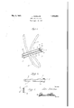
- Figure l is a perspective view showing the improved device and the manner in which it is used.
- Figure 2 is a side elevational view of the same.
- Figure 3 is a detail section on the line 33 of Figure 1.
- the complete device is of exceptionally simple construction, comprises a pair of companion resilient wire grips or jaws 4 and 5 connected in assembled relation to occupy a substantially spaced parallel relationship as seen in Figure 1.
- Each jaw is formed from a single length of wire bent upon itself in U-shaped form and the free ends of the arms of the respective U-shaped members are connected together. This is accomplished by utilizing a pair of thimbles or ferrules 6 and 7 of duplicate construction. As seen in Figure 3 the ferrule is somewhat elongated in cross sectional shape and formed from a strap of metal and fitted into the ferrule is a core or filler block 8 which serves as a spacing and retaining member which has its upper and lower edges 1931. Serial No. 533,552.
- the electric cord is denoted by the numeral 11 in Figure 1 and in order to shorten the cord all that is necessary is to double it upon itself to form a sort of a loop as indicated at 12 and to insert this loop between the jaws l and 5. This takes up the necessary surplus slack and permits the invention to fulfill the requirements in a desirable manner.
- An accessory of the class described comprising a pair of substantially spaced parallel resilient gripping elements, duplicate means maintaining said gripping elements in assembled relationship, and companion spacing and retaining elements fitted into each duplicate means.
- an electric cord clip of the class described comprising a pair of spaced superposed parallel companion gripping elements, said gripping elements each comprising a resilient U- shaped member, and means securing the open ends of each member together in assembled relationship.
- an electrical cord clip of the class described com prising a pair of companion resilient gripping jaws, each jaw being formed from a single length of wire bent upon itself into U- shaped configuration, a pair of opposed grooved blocks interposed between the free end portions of the corresponding arms of said jaws, and ferrules embracing the blocks and end portions to maintain said jaws in asembled spaced parallelism.
Landscapes
- Clamps And Clips (AREA)
Description
May 3, 1932. J. SCHILLER CORD HOLDING CLIP Filed April 28, 1931 I n venior A Home y Patented May 3, 1932 UE'E'ED STATES JOHN SCHILLER, OF WESTERN SPRINGS, ILLINOIS CORD HOLDING- CLIIP Application filed April 28,
This invention relates to a clip for oflice and home accessories, especially, but not necessarily, desi ned for application to an electricity conducting cord to aid in suspending a or holding the cord in an elevated position.
, It is a matter of common knowledge that electricity conducting cords used in connec tion with various electrical machines and appliances are frequently of such excess length m as to permit the cords to become entangled because of excess slack or to allow the cords to rest on the floor in an inconvenient and frequently troublesome manner.
The present invention comprehends a simple and economical resilient clip susceptible of quick application and removal and capable of maintaining surplus or excess portions of the cord in a doubled condition in such a way as to relieve the cord of excess slack and to permit it to be drawn suficiently taut as to allow it to be suspended on of the fioor at the point between the electrical appliance and the source of current supply.
In the drawings Figure l is a perspective view showing the improved device and the manner in which it is used.
Figure 2 is a side elevational view of the same.
Figure 3 is a detail section on the line 33 of Figure 1.
Referring to the drawings in detail, it will be observed that the complete device is of exceptionally simple construction, comprises a pair of companion resilient wire grips or jaws 4 and 5 connected in assembled relation to occupy a substantially spaced parallel relationship as seen in Figure 1.
Each jaw is formed from a single length of wire bent upon itself in U-shaped form and the free ends of the arms of the respective U-shaped members are connected together. This is accomplished by utilizing a pair of thimbles or ferrules 6 and 7 of duplicate construction. As seen in Figure 3 the ferrule is somewhat elongated in cross sectional shape and formed from a strap of metal and fitted into the ferrule is a core or filler block 8 which serves as a spacing and retaining member which has its upper and lower edges 1931. Serial No. 533,552.
grooved to receive the wire ends 9 and 10 of the respective jaws 4i and 5.
The electric cord is denoted by the numeral 11 in Figure 1 and in order to shorten the cord all that is necessary is to double it upon itself to form a sort of a loop as indicated at 12 and to insert this loop between the jaws l and 5. This takes up the necessary surplus slack and permits the invention to fulfill the requirements in a desirable manner.
It is thought that the description, taken in connection with the drawings will enable a clear understanding of the invention to be had. Therefore, a more lengthy description is thought unnecessary.
While the preferred embodiment of the invention has been shown and described, it is to be understood that minor changes coming within the field of invention claimed may be resorted to if desired.
I claim:
1. An accessory of the class described comprising a pair of substantially spaced parallel resilient gripping elements, duplicate means maintaining said gripping elements in assembled relationship, and companion spacing and retaining elements fitted into each duplicate means.
2. As a new product of manufacture, an electric cord clip of the class described comprising a pair of spaced superposed parallel companion gripping elements, said gripping elements each comprising a resilient U- shaped member, and means securing the open ends of each member together in assembled relationship.
As a new article of manufacture, an electrical cord clip of the class described com prising a pair of companion resilient gripping jaws, each jaw being formed from a single length of wire bent upon itself into U- shaped configuration, a pair of opposed grooved blocks interposed between the free end portions of the corresponding arms of said jaws, and ferrules embracing the blocks and end portions to maintain said jaws in asembled spaced parallelism.
In testimony whereof I aflix my signature.
JOHN SCHILLER.
Priority Applications (1)
| Application Number | Priority Date | Filing Date | Title |
|---|---|---|---|
| US533552A US1856594A (en) | 1931-04-28 | 1931-04-28 | Cord holding clip |
Applications Claiming Priority (1)
| Application Number | Priority Date | Filing Date | Title |
|---|---|---|---|
| US533552A US1856594A (en) | 1931-04-28 | 1931-04-28 | Cord holding clip |
Publications (1)
| Publication Number | Publication Date |
|---|---|
| US1856594A true US1856594A (en) | 1932-05-03 |
Family
ID=24126459
Family Applications (1)
| Application Number | Title | Priority Date | Filing Date |
|---|---|---|---|
| US533552A Expired - Lifetime US1856594A (en) | 1931-04-28 | 1931-04-28 | Cord holding clip |
Country Status (1)
| Country | Link |
|---|---|
| US (1) | US1856594A (en) |
-
1931
- 1931-04-28 US US533552A patent/US1856594A/en not_active Expired - Lifetime
Similar Documents
| Publication | Publication Date | Title |
|---|---|---|
| US2172174A (en) | Cable hanger | |
| US2309971A (en) | Drop wire support | |
| US1856594A (en) | Cord holding clip | |
| US1365762A (en) | Electric cord-holder | |
| US1730945A (en) | Flexible cord connection for electrical appliances | |
| US1514544A (en) | Automatic cord adjuster | |
| US1759417A (en) | Electrical cord support | |
| US1222510A (en) | Wire clothes-pin. | |
| US1939086A (en) | Supporting device | |
| US1506649A (en) | Sadiron-stand holder | |
| US1714201A (en) | Clothes hanger | |
| US2496173A (en) | Adjustable appliance plug | |
| US1584590A (en) | Cord holder and guide | |
| US2151226A (en) | Attachment plug | |
| US1996447A (en) | Clamping device | |
| US1499292A (en) | Attachment for clothespins | |
| DE472134C (en) | Ceiling clamp nipple | |
| US1954592A (en) | Wire support | |
| US1293055A (en) | Folding clothes-line. | |
| US2956104A (en) | Multiplex terminal spreader | |
| US1530844A (en) | Wire stretcher | |
| US2874923A (en) | Cable brackets | |
| US2457736A (en) | Wire clothespin | |
| US1176333A (en) | Insulator-pin. | |
| US1365722A (en) | Key attachment for electric-lamp sockets |