US1856580A - Pipe joint - Google Patents
Pipe joint Download PDFInfo
- Publication number
- US1856580A US1856580A US95535A US9553526A US1856580A US 1856580 A US1856580 A US 1856580A US 95535 A US95535 A US 95535A US 9553526 A US9553526 A US 9553526A US 1856580 A US1856580 A US 1856580A
- Authority
- US
- United States
- Prior art keywords
- gasket
- pipe
- joint
- bell
- spigot
- Prior art date
- Legal status (The legal status is an assumption and is not a legal conclusion. Google has not performed a legal analysis and makes no representation as to the accuracy of the status listed.)
- Expired - Lifetime
Links
- 239000002184 metal Substances 0.000 description 8
- 229910052751 metal Inorganic materials 0.000 description 8
- 239000000463 material Substances 0.000 description 7
- 239000002657 fibrous material Substances 0.000 description 4
- 230000007547 defect Effects 0.000 description 2
- 238000003780 insertion Methods 0.000 description 2
- 230000037431 insertion Effects 0.000 description 2
- 238000000034 method Methods 0.000 description 2
- 229910001018 Cast iron Inorganic materials 0.000 description 1
- 229910000831 Steel Inorganic materials 0.000 description 1
- 230000004308 accommodation Effects 0.000 description 1
- 230000004323 axial length Effects 0.000 description 1
- 238000010276 construction Methods 0.000 description 1
- 238000006073 displacement reaction Methods 0.000 description 1
- 238000001125 extrusion Methods 0.000 description 1
- 238000012857 repacking Methods 0.000 description 1
- 238000007789 sealing Methods 0.000 description 1
- 238000005476 soldering Methods 0.000 description 1
- 239000007787 solid Substances 0.000 description 1
- 239000010959 steel Substances 0.000 description 1
Images
Classifications
-
- F—MECHANICAL ENGINEERING; LIGHTING; HEATING; WEAPONS; BLASTING
- F16—ENGINEERING ELEMENTS AND UNITS; GENERAL MEASURES FOR PRODUCING AND MAINTAINING EFFECTIVE FUNCTIONING OF MACHINES OR INSTALLATIONS; THERMAL INSULATION IN GENERAL
- F16L—PIPES; JOINTS OR FITTINGS FOR PIPES; SUPPORTS FOR PIPES, CABLES OR PROTECTIVE TUBING; MEANS FOR THERMAL INSULATION IN GENERAL
- F16L13/00—Non-disconnectable pipe joints, e.g. soldered, adhesive, or caulked joints
- F16L13/12—Non-disconnectable pipe joints, e.g. soldered, adhesive, or caulked joints with a seal made of lead, caulked packing, or the like
- F16L13/122—Non-disconnectable pipe joints, e.g. soldered, adhesive, or caulked joints with a seal made of lead, caulked packing, or the like for male-female connections
Definitions
- PIPE JOINT Filedl March 18, 1926 Patented May 3, i932I UNITED STATES y PATENT o1-Fica JQHNZC. M ITCHELL, OFBLOOMFIELD, 4NEW JERSEY, ASSIGNOR T0 LOCK-J'OINT PIPE COMPANY, F AMPERE, NEW JERSEY, A CORERATION OIEv NEW JERSEY 4PIIEE JOINT 'Application led March 18, 1,926. Serial No. 95,535.
- rlhis invention pertains to improvements l in the pipe jointl disclosed in'Patent ⁇ No.
- Fig. l is a sectional view showing the gasket in position in the bell of a metal pipe
- Fig. 2 is the same asf Fig. 1 after the joint is made.
- Fig. 3 shows the joint applied to concrete pipe, after the gasket has been hand caulked.
- the spigot portion of the joint comprises acylindricalportion and a tapered end; portion 12.
- the bell portion of the joint comprises a bottom ring shaped surface 14, a cylindrical portion 16, and a gasket-receiving recessed portion which may be of any desired contour but which is shown as comprising an abutment ring surface 18 joined by a cone shaped surface 20, a cylindrical portion 22, and anannular recess 24 in surface 22.
- the gasket 26 is preferably formed by an extrusion process, with substantially the cross section shown'in Fig.v 1.
- the cross section shows a Vsubstantially rectangular portion and an inclined portion.
- the inclined portion is of such shape as to fit into the annular conical recess formed in the. pipe bell by surfaces 18 and 20.
- the inclined portion has approximately the same amount of metal per unit of length as the straight portion, but is f provided with a flattened tubular passage parallel tothe inclined walls, for the accommodation of fibrous material 28. lThe forming of this passage thickens the inclined portion .of the gasket so that it projects, as at 30, into thepath of the incoming spigot end of the next length of pipe.
- the gaskets are formed by extruding metal -with the above described cross section, drawing fibrous material through the hollow portion, cutting to'length, and joining the ends of each length, by soldering or fusing, to form a ring of proper length for insertion as indicated vin Fig. 1.
- the diameter of the gasket is greater than the diameter of the mouth of the bell, it is necessary to crimp or distort the gasket from its circular shape while ⁇ putting it in place.
- the gasket assumes substantially the shape shown in-Fig. 2.
- the shape ofthe precompressed ring was such as to permit the reformed material to take the shape illustrated, which is a form found highly eflicient for the desired purpose.
- the fibrous material is compressed into a comparatively long narrow cross section extending lengthwise of the pipe, and the straight portion 26 lof the gasket extends towards the open end
- Fig.' 3 shows a cross section of'a joint of a concrete pipe.
- the pipe comprises the concrete sections 32 and 34,
- spigot and bell ends being of metal, usually cast iron.
- this gasket permits the making of a tight joint by hand caulking, even though the spigot end, ⁇ gasket, and bell end are not so proportioned as to make a tight joint in the usual self-caulking manner. ⁇ In other words, the gasket may be placed comparatively loosely between bell and spigot, and the joint then made'tight by c'aulking the gasket.
- my present invention discloses a design of pipe joint in which the possibility of defect is reduced to a minimum; which may be made tight by self-caulking when the spigot is forced into the bell; which may be made tight entirely by hand-caulking, or 'by a combination of selfcaulking and handcaulking; and which may at any time 'be tightened by hand-caulking.
Landscapes
- Engineering & Computer Science (AREA)
- General Engineering & Computer Science (AREA)
- Mechanical Engineering (AREA)
- Gasket Seals (AREA)
Description
May 3, 1932 J. c. MITCHELL 1,856,580
PIPE JOINT Filedl March 18, 1926 Patented May 3, i932I UNITED STATES y PATENT o1-Fica JQHNZC. M ITCHELL, OFBLOOMFIELD, 4NEW JERSEY, ASSIGNOR T0 LOCK-J'OINT PIPE COMPANY, F AMPERE, NEW JERSEY, A CORERATION OIEv NEW JERSEY 4PIIEE JOINT 'Application led March 18, 1,926. Serial No. 95,535.
rlhis invention pertains to improvements l in the pipe jointl disclosed in'Patent` No.
. ship. with the pipe ends by and during the forcible insertion .of the spigot end Ninto the -in combination with an annular compressible gasket which Vis forced into'sealing relationbell end. f
In the above disclosed structure the oom,-v pressible gasket was made in the .most convenient manner-by using ordinary commerciall lead pipe, bought on the openmarket,
, drawing resilient fibrous material through the pipe, flattening to desired thickness, cutting to length, and fusing the ends together to form rings. -I l Such a method produced a serviceable and "fairly satisfactory gasket, but experience has taught that for best results, under all conditions of service, the details of the joint should be modified, particularly the distribution of metal in the gasket, and it is toward such improvements that my present invention" is directed. l
Further and other objects and advantages will be hereinafter set forth in the accom panying specification and claims and'sho'wn in the drawings, which byway of illustra- Ation show what is now considered to be the preferred embodiment of the invention.
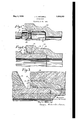
Fig. l is a sectional view showing the gasket in position in the bell of a metal pipe,
v before the spigot is forced to place.
Fig. 2 is the same asf Fig. 1 after the joint is made.
Fig. 3 shows the joint applied to concrete pipe, after the gasket has been hand caulked.
The spigot portion of the joint comprises acylindricalportion and a tapered end; portion 12. The bell portion of the joint comprises a bottom ring shaped surface 14, a cylindrical portion 16, and a gasket-receiving recessed portion which may be of any desired contour but which is shown as comprising an abutment ring surface 18 joined by a cone shaped surface 20, a cylindrical portion 22, and anannular recess 24 in surface 22.
The gasket 26 is preferably formed by an extrusion process, with substantially the cross section shown'in Fig.v 1. The cross section shows a Vsubstantially rectangular portion and an inclined portion. The inclined portion is of such shape as to fit into the annular conical recess formed in the. pipe bell by surfaces 18 and 20. The inclined portion has approximately the same amount of metal per unit of length as the straight portion, but is f provided with a flattened tubular passage parallel tothe inclined walls, for the accommodation of fibrous material 28. lThe forming of this passage thickens the inclined portion .of the gasket so that it projects, as at 30, into thepath of the incoming spigot end of the next length of pipe.
The gaskets are formed by extruding metal -with the above described cross section, drawing fibrous material through the hollow portion, cutting to'length, and joining the ends of each length, by soldering or fusing, to form a ring of proper length for insertion as indicated vin Fig. 1. As the diameter of the gasket is greater than the diameter of the mouth of the bell, it is necessary to crimp or distort the gasket from its circular shape while `putting it in place.
After the spigot has been forced into the bell, the gasket assumes substantially the shape shown in-Fig. 2. The shape ofthe precompressed ring was such as to permit the reformed material to take the shape illustrated, which is a form found highly eflicient for the desired purpose. In this form the fibrous material is compressed into a comparatively long narrow cross section extending lengthwise of the pipe, and the straight portion 26 lof the gasket extends towards the open end It may sometimes happen that a joint springs a leak-due, for` instance, to displacement of the pipe on account of shifting supports therefor, and it then becomes important to be able to caulk the joint by hand in order to take up the leak. Such a caulking operation is impractical with the type of gasket shown in the patent above referred to, because the exposed edge of the gasketdoes not offer enough metal for the purpose, and because any caulking of the exposed edge might cut through the wall of the metal and allow the escape of fibrous materiahthus reducing the expansive value of the fibrous core and making i necessary the entire rep-acking of the oln l/The present `design of gasket completely overcomes the above mentioned defect by providing the material 26 which may be successfully hand caulked.
The condition of the gasket after caulking is illustrated in Fig.' 3, which shows a cross section of'a joint of a concrete pipe. The pipe comprises the concrete sections 32 and 34,
formed around steel shells 36 and 38 respectively, and in which spigot end 38 and bell end 40 are inserted, the spigot and bell ends being of metal, usually cast iron.
- The gasket has been caulked until the portion which 'originally occupied the dotted space 26 has been compressed into the solid outline, completely filling the circumferen- \tial groove 24 provided for the purpose.
It will be noted that this gasket permits the making of a tight joint by hand caulking, even though the spigot end,`gasket, and bell end are not so proportioned as to make a tight joint in the usual self-caulking manner. `In other words, the gasket may be placed comparatively loosely between bell and spigot, and the joint then made'tight by c'aulking the gasket.
In the design disclosed in the above patent,
a circumferential groove was provided in the pipe bell,I somewhat similar to the .present groove formed by'surfaces 18.and 20, but noattempt was made to fit the gasket into that groove until pressure `was applied, whereupon the metal was expected to flow suiciently to completely lill the space, which it did not always do perfectly, thereby inviting a leak at the point not properly filled. In the present designall possibility of such a defeet is obvia-ted byl so forming the gasket s 'i imbedded therein, the thickness of the ductile material radially adjacent said resilient mateform volume of ductile material per unit of axial length, said material being provided with a circumferential cavity near one edge, saiill cavity being filled with resilient materia In testimony whereofI hereto aihiz my signature.
- JOHN C. MITCHELL.
that it tsthe groove before pressure is apf plied. v
From the above description it will be evii dent that my present invention discloses a design of pipe joint in which the possibility of defect is reduced to a minimum; which may be made tight by self-caulking when the spigot is forced into the bell; which may be made tight entirely by hand-caulking, or 'by a combination of selfcaulking and handcaulking; and which may at any time 'be tightened by hand-caulking.
It is to be understood that the invention is not limited to the construction herein speciiically illustrated but can be embodied in other forms without departure from its spirit.`
.I claim@l 1. A gasket' f or the purpose described, comprising in v`combination, a ring of ductile material, vand a ring of resillent material'
Priority Applications (1)
| Application Number | Priority Date | Filing Date | Title |
|---|---|---|---|
| US95535A US1856580A (en) | 1926-03-18 | 1926-03-18 | Pipe joint |
Applications Claiming Priority (1)
| Application Number | Priority Date | Filing Date | Title |
|---|---|---|---|
| US95535A US1856580A (en) | 1926-03-18 | 1926-03-18 | Pipe joint |
Publications (1)
| Publication Number | Publication Date |
|---|---|
| US1856580A true US1856580A (en) | 1932-05-03 |
Family
ID=22252447
Family Applications (1)
| Application Number | Title | Priority Date | Filing Date |
|---|---|---|---|
| US95535A Expired - Lifetime US1856580A (en) | 1926-03-18 | 1926-03-18 | Pipe joint |
Country Status (1)
| Country | Link |
|---|---|
| US (1) | US1856580A (en) |
Cited By (6)
| Publication number | Priority date | Publication date | Assignee | Title |
|---|---|---|---|---|
| US2991092A (en) * | 1957-07-05 | 1961-07-04 | American Cast Iron Pipe Co | Pipe coupling having a double sealing action gasket |
| US4637618A (en) * | 1984-07-13 | 1987-01-20 | Vassallo Research & Development Corporation | Composite gasket and fitting including same |
| US4693483A (en) * | 1984-07-13 | 1987-09-15 | Vassallo Research & Development Corporation | Composite gasket and fitting including same |
| EP0276785A3 (en) * | 1987-01-28 | 1989-07-26 | Gerhard Preisendorfer | Manufacture of sealable and insertable concrete pipes |
| US6250646B1 (en) * | 1999-10-08 | 2001-06-26 | Chye-Tao Chang | High pressure-high temperature pipe gasket |
| DE102006014439A1 (en) * | 2006-03-27 | 2007-10-11 | Appel Gmbh | Sealing ring manufacturing method for seam of socket, involves connecting reinforcement unit with circular sealing body, where sealing body is made of plastic, and extending circular sealing rim inward from sealing body |
-
1926
- 1926-03-18 US US95535A patent/US1856580A/en not_active Expired - Lifetime
Cited By (6)
| Publication number | Priority date | Publication date | Assignee | Title |
|---|---|---|---|---|
| US2991092A (en) * | 1957-07-05 | 1961-07-04 | American Cast Iron Pipe Co | Pipe coupling having a double sealing action gasket |
| US4637618A (en) * | 1984-07-13 | 1987-01-20 | Vassallo Research & Development Corporation | Composite gasket and fitting including same |
| US4693483A (en) * | 1984-07-13 | 1987-09-15 | Vassallo Research & Development Corporation | Composite gasket and fitting including same |
| EP0276785A3 (en) * | 1987-01-28 | 1989-07-26 | Gerhard Preisendorfer | Manufacture of sealable and insertable concrete pipes |
| US6250646B1 (en) * | 1999-10-08 | 2001-06-26 | Chye-Tao Chang | High pressure-high temperature pipe gasket |
| DE102006014439A1 (en) * | 2006-03-27 | 2007-10-11 | Appel Gmbh | Sealing ring manufacturing method for seam of socket, involves connecting reinforcement unit with circular sealing body, where sealing body is made of plastic, and extending circular sealing rim inward from sealing body |
Similar Documents
| Publication | Publication Date | Title |
|---|---|---|
| US1976589A (en) | Pipe joint | |
| US3325174A (en) | Pipe joint packing | |
| US2899984A (en) | Gaffin | |
| US2831711A (en) | Wedge ring detent pipe coupling | |
| NO116740B (en) | ||
| US1856580A (en) | Pipe joint | |
| US2288904A (en) | Pipe joint or coupling | |
| US1620728A (en) | Closure plug for pipes | |
| US1979141A (en) | Pipe joint and pipe joint gasket | |
| US2868576A (en) | Gasket for bell and spigot pipe joints | |
| US2582995A (en) | Closure joint | |
| US865497A (en) | Pipe-coupling and method of applying same. | |
| US2037084A (en) | Leak clamp for pipe joints | |
| US2632942A (en) | Method of joining together glass pipe sections | |
| US2842383A (en) | Sectional gasket ring for bell joint clamp | |
| US1983977A (en) | Pipe coupling | |
| US1949451A (en) | Pipe coupler | |
| US2347044A (en) | Pipe bell hub and sealing means | |
| US1856581A (en) | Pipe joint | |
| US2272812A (en) | Pipe joint | |
| US2145645A (en) | Pipe joint | |
| US2158829A (en) | Pipe joint packing | |
| US1980530A (en) | Solid ring pipe liner | |
| US1519111A (en) | Pipe coupling | |
| US2270296A (en) | Pipe coupling |