US1856538A - Toy and the like - Google Patents
Toy and the like Download PDFInfo
- Publication number
- US1856538A US1856538A US342724A US34272429A US1856538A US 1856538 A US1856538 A US 1856538A US 342724 A US342724 A US 342724A US 34272429 A US34272429 A US 34272429A US 1856538 A US1856538 A US 1856538A
- Authority
- US
- United States
- Prior art keywords
- arms
- bearing
- toy
- socket
- section
- Prior art date
- Legal status (The legal status is an assumption and is not a legal conclusion. Google has not performed a legal analysis and makes no representation as to the accuracy of the status listed.)
- Expired - Lifetime
Links
- 239000002184 metal Substances 0.000 description 7
- 229910052751 metal Inorganic materials 0.000 description 7
- 229910001018 Cast iron Inorganic materials 0.000 description 3
- 238000000926 separation method Methods 0.000 description 3
- XEEYBQQBJWHFJM-UHFFFAOYSA-N Iron Chemical compound [Fe] XEEYBQQBJWHFJM-UHFFFAOYSA-N 0.000 description 2
- 238000005266 casting Methods 0.000 description 2
- 238000003754 machining Methods 0.000 description 2
- 229910052742 iron Inorganic materials 0.000 description 1
- 230000000717 retained effect Effects 0.000 description 1
- ONSIBMFFLJKTPT-UHFFFAOYSA-L zinc;2,3,4,5,6-pentachlorobenzenethiolate Chemical group [Zn+2].[S-]C1=C(Cl)C(Cl)=C(Cl)C(Cl)=C1Cl.[S-]C1=C(Cl)C(Cl)=C(Cl)C(Cl)=C1Cl ONSIBMFFLJKTPT-UHFFFAOYSA-L 0.000 description 1
Images
Classifications
-
- B—PERFORMING OPERATIONS; TRANSPORTING
- B62—LAND VEHICLES FOR TRAVELLING OTHERWISE THAN ON RAILS
- B62K—CYCLES; CYCLE FRAMES; CYCLE STEERING DEVICES; RIDER-OPERATED TERMINAL CONTROLS SPECIALLY ADAPTED FOR CYCLES; CYCLE AXLE SUSPENSIONS; CYCLE SIDE-CARS, FORECARS, OR THE LIKE
- B62K9/00—Children's cycles
- B62K9/02—Tricycles
-
- A—HUMAN NECESSITIES
- A63—SPORTS; GAMES; AMUSEMENTS
- A63G—MERRY-GO-ROUNDS; SWINGS; ROCKING-HORSES; CHUTES; SWITCHBACKS; SIMILAR DEVICES FOR PUBLIC AMUSEMENT
- A63G1/00—Roundabouts
- A63G1/32—Roundabouts with seats two or more of which form a see-saw
-
- Y—GENERAL TAGGING OF NEW TECHNOLOGICAL DEVELOPMENTS; GENERAL TAGGING OF CROSS-SECTIONAL TECHNOLOGIES SPANNING OVER SEVERAL SECTIONS OF THE IPC; TECHNICAL SUBJECTS COVERED BY FORMER USPC CROSS-REFERENCE ART COLLECTIONS [XRACs] AND DIGESTS
- Y10—TECHNICAL SUBJECTS COVERED BY FORMER USPC
- Y10T—TECHNICAL SUBJECTS COVERED BY FORMER US CLASSIFICATION
- Y10T403/00—Joints and connections
- Y10T403/32—Articulated members
- Y10T403/32975—Rotatable
- Y10T403/32983—Rod in socket
Definitions
- This invention relates to toys or the like, Vand particularly to inexpensivetoys whlch' may be made of cast metal.
- An object of the invention is to provide an improved toy or the like, which may be made partially or entirely of cast metal; which will comprise articulated parts, and in which the articulately connected parts may be assembled or disassembled in an easy, simple and rapid manner without the use of tools and nuts, screws, pins, bolts or other parts which 'mi ht become lost.
- V ⁇ nother object of the invention is to provide animproved toy or the like with articu- 'lately connected parts which may be formed largely or entirely ⁇ of cast metal; which will require no machine finishing operations, and which will be relatively simple, durable and inexpensive.
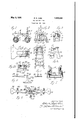
- Fig. l is a side elevation of a toy vehicle formed largely of cast metal and constructed Ain accordance with this invention.
- Fig. 2 is an end elevationk of the same.
- Fig. 3 is asectional elevation of a portion of the same, the section being taken approximately along the line 3-3 of Fig. l.
- Fig. 4 is a sectional plan ofthe same, the
- FIG. 5 is a front elevation vof a toy stepv ladder also constructed in accordance with 'this ⁇ invention and illustrating another embodiment thereof;
- Fig. 6 is a transverse sectional elevation of a portion of the same, the section being taken approximatelyV along the line 6-6 of Fig. 5.
- Fig. 7 is a sectional elevation of a portion 'of the same with the section taken appproxiniatelyalong the line 7 7 of Fig. 5.
- Fig. 8 is'an elevation of a toy merry-goround andMteeter-totter, alsoconstructed in accordance with the invention and illustrating another embodiment'thereof;
- Fig. 10 is a sectional elevation of a portion of the same, the section being taken approxiniately along the line 10--10 Fig. 9.
- the toy vehicle comprises a frame 1 having depending arms 2 mounting rear wheels 3, and the seat portion 4 has the usual narrow, forwardly extending portion, which in this example consists of two arms 5 connected together at the connection of the narrow portion to the wider seat portion, the arms at their other ends being free to spring apart to a limited extent.
- the arms 5, at points adjacent their free ends, are provided with concave seats 6 which together form between them a socket or bearing for the steering post or standard 7.
- the post 7 may include an upright standard hav.- ing ,handles 8 at the upper end thereof, and forked arms 9 at the lower end thereof for mounting a forward steering wheel l() in any suitable manner.
- the intermediate portion of the standard 7 is provided with a shaft-like bearing section 11, with shoulders 12 and 13 7 l at opposite ends of this bearing section, This bearing section is round in cross section and is intended to be rotatably mounted in the cavity or socket formed by the concave seats 6 at the free ends of the arms 5.
- the free ends of the arms 5 extend toward one another atthe sockets 6 sufficiently to maintain the bearing section 11 against separation therefrom while permitting a turntreme outer ends of the arms 5, however, have diverging faces 14 leading to the seats 6, and the distance between the inner ends or edges of these diverging faces is slightly less than the diameter of the bearing section l1, so that when the bearing section 11 is forced between the arms 5 through the space between the diverging faces 14, the arms 5 will be sprung apart at their free ends, and the bearing secformed by the convex seats 6.
- the arms 5 will then yieldingly prevent separation therefrom of the front standard 7.
- the front standard may Vbe separated from the rear section of the Vehicle by forcing it outwardly through the space-between the di- ⁇ verging faces 14, during which the arms 5 will be sprung apart slightly at their free ends.
- the bearing section 11 may -4be frusto-cenical, ⁇ and the concave bearing @seats 6of the bearingor socketbetweenthe Yed .to the. fra-Ine ⁇ and the front standard by suitable .rivets A-. a1idl B.
- connection may be easily effected or a disconnection niadeinerely by springing to'ward'one an.
- a suitable base l22 ⁇ is provided with an,upwardlyprojecting post .23 having avbearingv orshaftflikesection 24,
- the upper or terminal endor head V27jlof thepost 28 may be.. tapered or approximately. .semi- 2spherical on domeshapedfor al purpose which will. appear presently,y
- the shoulder 25 is relativelynarrow softhat K :be .forced .or .sprung apart. slightly to -enable the lugs tofsnap overthe, head and ⁇ around the bearing section 24 whereitzwillbe beneath the ⁇ shoulder125.
- the frame 28 may thus Aswung-,about the bearing section.24when vthe toy -isto be 1 usedvas a merry-go-round, andtheupper faces of the lugsV leadingtozthe socketmayi'be ⁇ bevelled as at 34 so as to clear the shoulder25 n .and permita limitedteetering'or see-sawing spring-able at theirfreeends, are sprung vl-toward one,- another somewhat as VVillustrated r-vindash lines in Figs.I 5 and 7 so that the studsv Vorvpinsv 211can1pa-ssinto the front frame 15 In all these exainpleavthefpartsmay be largely or entirely of cast metal, suchJascast iron, and.
- a toy comprising a pair of elements formed of cast iron and pivotally connected to one another through cooperating bearing portions, the bearing portion of one of said elements being a post having an annular bearing groove, the bearing portion of the other element including a socket adapted to fit said post at said annular groove, said other element having a slot extending away from said socket but at its junction therewith having a width slightly less than the diameter of said socket, said slot extending a substantial dis- .tance away from said socket to provide a pair of arms suiiiciently yieldable to enable engagement and disengagement of said socket and said post.
- an improved joint between said member and base comprising an upright standard on said base and terminating at its upper end in a vertical bearing post with an enlarged terminal head Vat its upper -free end, said member being formed of cast iron and having between its ends a socket of a size to fit and rotate on said A post and slightly smaller than the diameter of said terminal head, said member being slotted through the socket portion yand for some distance therefrom in opposite directions to provide relatively slender arms connected together at both ends, and between their ends supporting the socket portions which may spring apart to enable passage of said socket portion over the head of said post into rotating engagement with said post.
Landscapes
- Engineering & Computer Science (AREA)
- Mechanical Engineering (AREA)
- Toys (AREA)
Description
May 3', A1932. E, R` CASE 1,856,538
TOY AND THE LIKE Filed Feb. 26, 1929 LR Il z5 3/ /J f if ff Patented May 3, 1932 UNiTlazI-D STATES PATENT OFFICE EDWARD RALPH CASE, OF LANCASTER, lPENNSYLVANIA, ASSIGNOR, BY MESNE AS- SIGNMENTS, TO THE KILGOR-E rIVIANUFAC'IIURINGr COMPANY, OF WESTERVILLE,
TOY AND THE LIKE Application filed February 26, 1929. Serial No. 342,724.
This invention relates to toys or the like, Vand particularly to inexpensivetoys whlch' may be made of cast metal. An object of the invention is to provide an improved toy or the like, which may be made partially or entirely of cast metal; which will comprise articulated parts, and in which the articulately connected parts may be assembled or disassembled in an easy, simple and rapid manner without the use of tools and nuts, screws, pins, bolts or other parts which 'mi ht become lost.V `nother object of the invention is to provide animproved toy or the like with articu- 'lately connected parts which may be formed largely or entirely `of cast metal; which will require no machine finishing operations, and which will be relatively simple, durable and inexpensive. Various other objects andadvantages will lbe apparent from the following description of several embodiments of the invention, and the novel features will be particularly pointed out hereinafter in connection with the ap- 25 pended claims;Y
In the accompanying drawings: Fig. l is a side elevation of a toy vehicle formed largely of cast metal and constructed Ain accordance with this invention.
Fig. 2 is an end elevationk of the same.
' Fig. 3 is asectional elevation of a portion of the same, the section being taken approximately along the line 3-3 of Fig. l.
Fig. 4 is a sectional plan ofthe same, the
Y section being taken approximately along the line 4 4', Fig. 1.
- Fig. 5 is a front elevation vof a toy stepv ladder also constructed in accordance with 'this `invention and illustrating another embodiment thereof; v
Fig. 6 is a transverse sectional elevation of a portion of the same, the section being taken approximatelyV along the line 6-6 of Fig. 5. Fig. 7 is a sectional elevation of a portion 'of the same with the section taken appproxiniatelyalong the line 7 7 of Fig. 5. Fig. 8 is'an elevation of a toy merry-goround andMteeter-totter, alsoconstructed in accordance with the invention and illustrating another embodiment'thereof;
fing vof the bearing section therein. The eX- tion 11 will move into the cavity or bearing Fig. 9 is a plan of the same.
Fig. 10 is a sectional elevation of a portion of the same, the section being taken approxiniately along the line 10--10 Fig. 9.
In the embodiment of the invention illustrated in Figs. 1 to 4, the toy vehicle comprises a frame 1 having depending arms 2 mounting rear wheels 3, and the seat portion 4 has the usual narrow, forwardly extending portion, which in this example consists of two arms 5 connected together at the connection of the narrow portion to the wider seat portion, the arms at their other ends being free to spring apart to a limited extent.
The arms 5, at points adjacent their free ends, are provided with concave seats 6 which together form between them a socket or bearing for the steering post or standard 7. The post 7 may include an upright standard hav.- ing ,handles 8 at the upper end thereof, and forked arms 9 at the lower end thereof for mounting a forward steering wheel l() in any suitable manner. The intermediate portion of the standard 7 is provided with a shaft-like bearing section 11, with shoulders 12 and 13 7 l at opposite ends of this bearing section, This bearing section is round in cross section and is intended to be rotatably mounted in the cavity or socket formed by the concave seats 6 at the free ends of the arms 5.
The free ends of the arms 5 extend toward one another atthe sockets 6 sufficiently to maintain the bearing section 11 against separation therefrom while permitting a turntreme outer ends of the arms 5, however, have diverging faces 14 leading to the seats 6, and the distance between the inner ends or edges of these diverging faces is slightly less than the diameter of the bearing section l1, so that when the bearing section 11 is forced between the arms 5 through the space between the diverging faces 14, the arms 5 will be sprung apart at their free ends, and the bearing secformed by the convex seats 6.
The arms 5 will then yieldingly prevent separation therefrom of the front standard 7. The front standard with its guide or steering wheel 10 may be turned about its 100 fr? machining and=will lit one. anotherV and vertical aXis as in any childs Vehicle, and
the parts Vwill be yieldingly retained in assembled relation to one another. The front standard, however, may Vbe separated from the rear section of the Vehicle by forcing it outwardly through the space-between the di- `verging faces 14, during which the arms 5 will be sprung apart slightly at their free ends. If desired, the bearing section 11 may -4be frusto-cenical,` and the concave bearing @seats 6of the bearingor socketbetweenthe Yed .to the. fra-Ine `and the front standard by suitable .rivets A-. a1idl B. The bearing Vsection 11 .andythev'seats 6 4do ynot require 'V adjustthemselves to -minor Ivari'ations ,in y dimensions owingto the slender arms 5 which maybe sprung'slightly for this purpose.y
I nthe embodimentillustrated in Figs: 5 to 7 a toy fstep-.ladder-is selected ,asthe example,
iniwhichthe rontiframev or step portionl .maygbeformed of one casting and the `rear `@frame or prop116 `formed of another casting.
.pointfadjaeentzor just below. the topfstep.
' 1.7-,Kinay lbe provided 'on their? inner Vfaces with f hearingcavitiesl, which for, yconvenience in ypastingmaybe slotsextending inwardly for some distance from the forward faceor edge :of 1theqframe. l-'I`he-rear frame. or prop 16 yniaycomprise twoside arms or legs which are connectedtogetherby suitable-integral braces .19. adjacent theirjlower ends, the .sideVv arms fbeing treefat their upper endsv so .that they ,n may f fromfoneanother.-
spring to a certain extent toward. and
. rTheupperends of theseside arms v:of the I .':prop f1.6' are=provide`dwith forwardly extending'branches or stub Jams 20,- andV each stub arm 2O at its-forward .endis provided with a laterally extending bearing stud or shaft- ..."l'ikepin21. v`z'llheseqpinsor studs 21in this Y.-= particularV 'example lextend in a. direction away from oneanother, andthe stubarms 2O o'f-gthe rear'flframe extendibetween the sideV arins'orA strips ofthe front frame15-ro1n thev frear-thereof, with thegpinsor'stud's 21'1en-f .gaged in thesoclets 18.
To placethestuds'or pins 21 .in thesoclrets 18,the sidearms 16-of the rear prop or frame,
which `arerelatively slender so as to be slightsockets 18, `whereuponwhenfthe free ends ofv from the rear thereotun'tilalined withff'the ,thefside armsof the frame 16 are released,
.pins 21 into. the sockets.
other at their upper ends, andthe connection may be easily effected or a disconnection niadeinerely by springing to'ward'one an.
other lthe upper, free ends of the f relatively slenderside arms of the rear frame or prop In the embodiment of the invention illustrated in FigsS to 10, a suitable base l22` is provided with an,upwardlyprojecting post .23 having avbearingv orshaftflikesection 24,
withl shoulders 25 and .26 at opposite :endsof the section, as shown clear-ly.- in Fig.10. f The upper or terminal endor head V27jlof thepost 28 may be.. tapered or approximately. .semi- 2spherical on domeshapedfor al purpose which will. appear presently,y
A. "eeter` or. swinging fframe. is provided with suitableininiature yseats 29 at, its ends, and handlelugs SOVadjacent thereto atthe ends, the end sections beingr connectedto one another by; relatively slendeifarms 81. which The side'niembers-ofy the front frame 15, at a other intermediate their. ends, as .illustrated- `in Fig. 9. .At a .centralpoint each armV 31 is are spaced. apart :andunconnectedto one anp rovided. .with fa lu g 32 extending towardv the other arm, andthe. `'adj acent faces: 33 of these lugs are concave so as to form between them a bea-ring socket for pivotalengfagementwith .the bearingsection=24 of the standardpost v23.
The shoulder 25 is relativelynarrow softhat K :be .forced .or .sprung apart. slightly to -enable the lugs tofsnap overthe, head and` around the bearing section 24 whereitzwillbe beneath the` shoulder125.
.An intermediate step infthis separation is illustrated bythe ldash-'lines .in Figs. 9and 10, the dash llines representing the various relative positions ofthe arinsl'andlugs 32 as thelugsare sprung over the `head-27.
.The frame 28 may thus Aswung-,about the bearing section.24when vthe toy -isto be 1 usedvas a merry-go-round, andtheupper faces of the lugsV leadingtozthe socketmayi'be `bevelled as at 34 so as to clear the shoulder25 n .and permita limitedteetering'or see-sawing spring-able at theirfreeends, are sprung vl-toward one,- another somewhat as VVillustrated r-vindash lines in Figs.I 5 and 7 so that the studsv Vorvpinsv 211can1pa-ssinto the front frame 15 In all these exainpleavthefpartsmay be largely or entirely of cast metal, suchJascast iron, and. although such cast-metals' do not lhave a high degree of resiliency, nevertheless by using a `good grade -ofcast nietalor cast iron,` there issuflicient 'springiness or resiliency in the metal of the -relativelyilong,slender arms to permit the making or breaking of the articulated connections between the variy out frame. parts. No machining operations are required, and the cost of articulated toys is thus reduced to a very low ligure, so that articulated toys of this type may be sold to the ive and ten cent store trade at a profit.
It will be obvious that various changes in the details, which have been hereindescribed and illustrated in order to explain the nature Vof the invention, may be made by those skilled in the art within the principle and scope of the invention as expressed in the appended Y claims.
I claim as my invention:
l. A toy comprising a pair of elements formed of cast iron and pivotally connected to one another through cooperating bearing portions, the bearing portion of one of said elements being a post having an annular bearing groove, the bearing portion of the other element including a socket adapted to fit said post at said annular groove, said other element having a slot extending away from said socket but at its junction therewith having a width slightly less than the diameter of said socket, said slot extending a substantial dis- .tance away from said socket to provide a pair of arms suiiiciently yieldable to enable engagement and disengagement of said socket and said post.
2. In a toy of the type having a base and a member rotatably connected thereto, an improved joint between said member and base comprising an upright standard on said base and terminating at its upper end in a vertical bearing post with an enlarged terminal head Vat its upper -free end, said member being formed of cast iron and having between its ends a socket of a size to fit and rotate on said A post and slightly smaller than the diameter of said terminal head, said member being slotted through the socket portion yand for some distance therefrom in opposite directions to provide relatively slender arms connected together at both ends, and between their ends supporting the socket portions which may spring apart to enable passage of said socket portion over the head of said post into rotating engagement with said post.
EDWARD RALPH CASE.
Priority Applications (1)
| Application Number | Priority Date | Filing Date | Title |
|---|---|---|---|
| US342724A US1856538A (en) | 1929-02-26 | 1929-02-26 | Toy and the like |
Applications Claiming Priority (1)
| Application Number | Priority Date | Filing Date | Title |
|---|---|---|---|
| US342724A US1856538A (en) | 1929-02-26 | 1929-02-26 | Toy and the like |
Publications (1)
| Publication Number | Publication Date |
|---|---|
| US1856538A true US1856538A (en) | 1932-05-03 |
Family
ID=23343009
Family Applications (1)
| Application Number | Title | Priority Date | Filing Date |
|---|---|---|---|
| US342724A Expired - Lifetime US1856538A (en) | 1929-02-26 | 1929-02-26 | Toy and the like |
Country Status (1)
| Country | Link |
|---|---|
| US (1) | US1856538A (en) |
Cited By (8)
| Publication number | Priority date | Publication date | Assignee | Title |
|---|---|---|---|---|
| US2671983A (en) * | 1951-07-13 | 1954-03-16 | Nosco Plastics | Toy airplane |
| US2700248A (en) * | 1952-07-03 | 1955-01-25 | Margon Corp | Eye for dolls |
| US2778159A (en) * | 1954-03-31 | 1957-01-22 | Kaysun Inc | Wheel mounting |
| US2786305A (en) * | 1954-05-21 | 1957-03-26 | Joseph H Carter | Toy tractor |
| US3020672A (en) * | 1959-07-03 | 1962-02-13 | Lionel Corp | Collapsible toy bridge |
| DE1163209B (en) * | 1961-02-09 | 1964-02-13 | Lothar Wilhelmi | Crane and railway toys |
| US3643005A (en) * | 1970-08-05 | 1972-02-15 | Lyle H Mathews | Conduit with spacer |
| US9289077B1 (en) * | 2013-08-28 | 2016-03-22 | Andrews K. Gyasi | Baby walker systems |
-
1929
- 1929-02-26 US US342724A patent/US1856538A/en not_active Expired - Lifetime
Cited By (8)
| Publication number | Priority date | Publication date | Assignee | Title |
|---|---|---|---|---|
| US2671983A (en) * | 1951-07-13 | 1954-03-16 | Nosco Plastics | Toy airplane |
| US2700248A (en) * | 1952-07-03 | 1955-01-25 | Margon Corp | Eye for dolls |
| US2778159A (en) * | 1954-03-31 | 1957-01-22 | Kaysun Inc | Wheel mounting |
| US2786305A (en) * | 1954-05-21 | 1957-03-26 | Joseph H Carter | Toy tractor |
| US3020672A (en) * | 1959-07-03 | 1962-02-13 | Lionel Corp | Collapsible toy bridge |
| DE1163209B (en) * | 1961-02-09 | 1964-02-13 | Lothar Wilhelmi | Crane and railway toys |
| US3643005A (en) * | 1970-08-05 | 1972-02-15 | Lyle H Mathews | Conduit with spacer |
| US9289077B1 (en) * | 2013-08-28 | 2016-03-22 | Andrews K. Gyasi | Baby walker systems |
Similar Documents
| Publication | Publication Date | Title |
|---|---|---|
| US1856538A (en) | Toy and the like | |
| GB461587A (en) | Improvements in spring suspension means for wheeled vehicles | |
| GB426704A (en) | Improvements in and relating to springing arrangements for vehicles | |
| US1778143A (en) | Wheeled toy | |
| GB845571A (en) | Improvements relating to wheel suspensions for motor vehicles | |
| GB840583A (en) | Improvements relating to vehicle road wheel suspension | |
| US1930619A (en) | Bogie construction | |
| US1974330A (en) | Toy train | |
| US1422277A (en) | Child's carriage | |
| US2506139A (en) | Dump trailer | |
| US35207A (en) | Improvement in shackles for railroad-cars | |
| US244433A (en) | Feancis w | |
| US479563A (en) | William j | |
| US1377980A (en) | Spring suspension of motor road-vehicles | |
| US1321714A (en) | Draft attachment | |
| US71805A (en) | Improvement in carriages | |
| GB405969A (en) | Improvements in portable seats | |
| US1924388A (en) | Running gear | |
| US1356966A (en) | Neck-yoke | |
| US2095698A (en) | Ox yoke model | |
| US1310264A (en) | Top-frame fob | |
| US634456A (en) | Thill-coupling. | |
| US810247A (en) | Folding baby-carriage and cradle. | |
| US1284955A (en) | Headlight. | |
| US981761A (en) | Truck. |