US1856537A - Method of pumping and system therefor - Google Patents
Method of pumping and system therefor Download PDFInfo
- Publication number
- US1856537A US1856537A US387990A US38799029A US1856537A US 1856537 A US1856537 A US 1856537A US 387990 A US387990 A US 387990A US 38799029 A US38799029 A US 38799029A US 1856537 A US1856537 A US 1856537A
- Authority
- US
- United States
- Prior art keywords
- fluid
- stream
- whirling
- pumped
- pumping
- Prior art date
- Legal status (The legal status is an assumption and is not a legal conclusion. Google has not performed a legal analysis and makes no representation as to the accuracy of the status listed.)
- Expired - Lifetime
Links
Images
Classifications
-
- F—MECHANICAL ENGINEERING; LIGHTING; HEATING; WEAPONS; BLASTING
- F04—POSITIVE - DISPLACEMENT MACHINES FOR LIQUIDS; PUMPS FOR LIQUIDS OR ELASTIC FLUIDS
- F04F—PUMPING OF FLUID BY DIRECT CONTACT OF ANOTHER FLUID OR BY USING INERTIA OF FLUID TO BE PUMPED; SIPHONS
- F04F5/00—Jet pumps, i.e. devices in which flow is induced by pressure drop caused by velocity of another fluid flow
- F04F5/02—Jet pumps, i.e. devices in which flow is induced by pressure drop caused by velocity of another fluid flow the inducing fluid being liquid
Definitions
- the present invention relates to pumps .tailed description, the ,system is shown in and pumping systems.
- Figures 1 and 5 it comprises a downward
- An object of the invention is to provide pressure-feed conduit 10, through which a an improved pumping method and system stream of fluid, preferably water, may be di- 5 for practicingthe method; also to provide rected into the lower end of a housing 11.
- a pump-of improved construction which al- The stream passes under pressure upwardly though of general application, is particular- -lthrough the housing, as indicated by the arly adapted for practicing my improved methrows 12 ( Figure 4) along a path substanod, and for use in connection with the pumptially' tangential to an annular chamber 13.
- Fluid, shallow-well pumps, and their lifting capacsuch as water is forced downwardly under ity does not usually exceed approximately suitable pressure in the pipe 10, so that it thirty two (32) feet. .will travel upwardly through the passage
- Another object of the invention is to prointermediate thel tapering portions 14, 14 75 vide ka systemand method'for pumping which and through a port located between the points is simple, comparatively inexpensive, and 16 and 17 with lthe chamber 18.
- a still further object is to provide a pump-v lmparted thereto by the stream traveling 80 ing system.
- Figure 1 is a somewhat diagrammatic outerably at the center l8'of the whirlpool, with line of the pumping system.
- Figure 2 is a cross sectional viewfon the a pipe 19fserving this purpose.
- he pipe line 2 2 of Figure 1 of one'of the two pumps may, if desired, be provided with a ⁇ foot valve 5 employed.
- F Figure 1 of suitable construction.
- 96 Figure 3 is a view of one 'of the system The rapidmotion' of the whirling body of units which is located within the well.
- the fluid pumped will be conducted off,l in the present from which it forced through the pipe 10 80 instance with the stream forcedzthrough. the to the well unit or housing 1'1.
- the fluid pumped is causedto pumps 20, 21, may be driven in any suitable enter the traveling stream bothby the cenmanner; in Figure 1 they are shown side by y trifugal action of the whirling body, which side, although they may be disposed in tan- 20 causes the excess fluid to pass through the port dem relation so as to be actuated by a combetween the Walls 16, 17, and also by theinmon vdrive shaft, as well as acommon rotor. jector action of thev stream as it passes this It will be understood that although the port.
- the pump 20 may said body as the body increases in volume. 40 serve as a pressure pump forforcing down- 2.
- the method of pumping which consists 105 Wardly fluid under pressure in the pipe 10, in forming a stream of liquid, maintaining and the pump 21 as a suction pump for assista whirling body ofliquid on a horizontal axis ing in lifting the fluid throughfthe pipe 10 by said stream', utilizing the whirling body to which communicates with the upper end of lift from a ,lowerv elevation by suction there ⁇ the vwell unit or housing 11.
- the pump 20 into fluid to be pumped, and taking off the 11( may be of considerably smaller vcapacity than pumped fluid from above said body 'as the thek pump 21 and may receive its fluid from body yincreases in volume, s a storage tank 22 through a suitable connec- 3.
- the method of pumping which consists tion 23 whichreturns to the pump20 fluid in in forming a stream of liquid, maintaining a considerably smallervolume than is introa vwhirling bodyv of liquid by directing the 11i cuted into the tank from a discharge pipe 24 said 'stream along a path tangential to the of the pump 2,1.
- the pumps 20, 21 arey of whirling body, utilizing the whirling body to identical construction, and as illustrated in lift from a lower elevation thereinto addi- Figure 2, each comprises a casing section 25 tional fluid to bepumped, and taking off the having a raceway 26which has oneend compumpedufluid Afrom above said body as the 12 municating with an inlet chamber 27 and they body increases in volume. other kend communicating with an outlet 4.
- the method of pumping,' which consists chamber 28 having its Wall thinned or bevelled in forming a stream of liquid, maintaining a as at 28 where the water enters the chamber. whirling body of liquid by the said stream,
- Water entering the raceway 26 is conducted utilizing thewhirlingbody to suck thereinto 1i around the same by the rotor 29, which is proat approximately its center additional fluid vided rvwith a plurality yof impelling buckets to be pumped, and taking olif the pumped fluid 30. as described in my patent above mentioned. from said body as it increases in volume.
- the method of pumping which consists in forming and maintaining a whirling body of liquid by a stream of' liquid, utilizing the whirling body to lift thereinto additional fluid to be pumped, introducing the pumped fluid from said body into said stream and conducting the said fluid off in said stream.
- The. method of pumping which consists in forming and maintaining a whirling body of liquid by a stream of liquid, utilizing b the whirling body to lift thereinto from a lower elevation additional fluid to be pumped,
- pumping which consists 1n forming and maintaining a whirling body of liquid by a stream of liquid substantially tangential to the whirling body, utilizing the whirling bodyl to lift from a lower elevation thereinto at approximately its center additional fluid to be pumped, and taking off the pumped fluid from said body as it increases in volume.
- the method of pumping which consists in forming and maintaining body of liquid bythe action of a liquid, utilizing the stream of whirling body to lift additional its center addif o ducing a fluid a whirlingl fluid to be pumped, taking off from said bodylinto said stream as it increases in volume the pumped fluid, and the fluid away in said stream.
- means for producing a fluid stream means for creating by said stream a whirling body of, liquid, means for placing said whirling body in communication with a body of fluid to lift the same from a lower elevation, and means for taking off pumped fluid from said body as the body increases in volume.
- means for producing a liquid stream means for creating y said'stre'am a whirling body of liquid, meansvfor placing said whirling body in communication Iwith the same from a lower elevation, and means for taking ofl' ⁇ pumped fluid from said body as the body increases in volume.
- means for producing a fluid stream means for producing a fluid stream, means .for creating by said stream a whirling body of liquid with the adjacent path'of the stream substantially tangential to said body, means for placing said whirling body in communication with a body of fluid to lift the same from a lower elevation, and means for takin off pumped fluid from said body as the body increases in volume.
- means for producing a fluid stream means for creating by said stream a whirling body of liquid, means or placing said whirling body at substantially its center in communication with a body of fluid to lift the same from a lower elevation, and means for taking off pumped fluid from said body as the body increases conducting b 1n volume.
- means for producing a fluid stream means for creating by said stream a whirling body of liquid with the adjacent path of the stream substantially tangential to said body, means for placingsaid whirling body at substantially its center in communication with a body of fluid to lift the same from a lower elevation, d means for taking oil pumped fluid from said body above the same as the body increases in volume.
- means for p stream means for creating by d stream a whirling body of liquid with t ie adjacent path of the stream substantially tangential to said body, means for placing said whirling body at substantially its center with a body of fluid to lift the same from a lower elevation, and means :for taking ofl' pumped fluid into said stream from said body as the body increases in volume.
- means for producing a fluid stream means for creating by said stream a whirling body of liquid with f the adjacent path of the stream substantially tangential to said body means for placing sai whirling body at substantially'its center in communication with a body of fluid to lift the same from a lower elevation, and means for taking oi pumped fluid into said stream from the periphery of said body above J c the same as the ody increases in vo ume.
- a pump comprising a body having a circular chamber arranged in a verticalplane, an inner conduit communicating with the axis of said chamber, saidbody having an inner port Aconverging to tangentially 'communicate with the bottom of said chamber, said body having an outlet port diverging upwardly rand tangentally Jfrom said chamber opposite saidxtangential inlet, and conduits connected to said tangential inlet and outlet for conducting a stream of fluid under pressure and tocreate in saidfcircular chamber a whirling body of fluid to lift fluid rstfrom saidinlet conduit and introduce it into'the axis of said whirling body of fluid.
Landscapes
- Engineering & Computer Science (AREA)
- Physics & Mathematics (AREA)
- Fluid Mechanics (AREA)
- Mechanical Engineering (AREA)
- General Engineering & Computer Science (AREA)
- Jet Pumps And Other Pumps (AREA)
Description
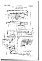
May 3, 1932. A. w. .B URKS METHOD 0F PUMPING AND SYSTEM THEREFOR Filed Aug. 23, 1929 )may mmv
,Patented May 3, 132 l UNITED, STATES PATENT OFFICE ARTHUR W. BURKS, F DECATUR, ILLINOIS METHOD 0F PUMPING-AND SYSTEM '.LHIEIBJBFOR Application fled-August 23,192.9, Serial No. 387,980.
The present invention relates to pumps .tailed description, the ,system is shown in and pumping systems. Figures 1 and 5; it comprises a downward An object of the inventionis to provide pressure-feed conduit 10, through which a an improved pumping method and system stream of fluid, preferably water, may be di- 5 for practicingthe method; also to provide rected into the lower end of a housing 11. 55 a pump-of improved construction, which al- The stream passes under pressure upwardly though of general application, is particular- -lthrough the housing, as indicated by the arly adapted for practicing my improved methrows 12 (Figure 4) along a path substanod, and for use in connection with the pumptially' tangential to an annular chamber 13.
ing system herein disclosed. Y its entrance end the housing 11 is proa0' The method and system are illustrated and vlded with a tapered passa e 14 adapted to described in connection with ya pump of the increase the velocity of the uid as it travels rotary type, a pump of this character being past the chamber 13; and at the upper end described, for example, in my Patent of the-housing there is formed a gradually 15 1,686,549, granted October 9, 1928. Pumps enlarging passage 14 adapted to decrease the e5 of this type are generally recognized as velocity, but increase the pressure. Fluid, shallow-well pumps, and their lifting capacsuch as water is forced downwardly under ity does not usually exceed approximately suitable pressure in the pipe 10, so that it thirty two (32) feet. .will travel upwardly through the passage An object of the present invention is to and housing 11 at relatively high velocity. 70 provide a method and system which, when Any suitable means may be provided yfor employed in connection witha pump of this creating-this fluid stream, and means suittype, will increase its lifting capacity and ablegfor *his purpose `will be later described. adapt it lfor deep-well pumping. The passage in the housing communicates Another object of the invention is to prointermediate thel tapering portions 14, 14 75 vide ka systemand method'for pumping which and through a port located between the points is simple, comparatively inexpensive, and 16 and 17 with lthe chamber 18. A body which, since it comprises few mechanical or,.-. of water intIOCluced linto the chamber 13, moving parts, is reliable in operation; for instance, from the fluid stream will have A still further object is to provide a pump-v lmparted thereto by the stream traveling 80 ing system. and` method of high capacity,throughxthe housing, a whirling'motion, which may be varied throughout a very wide which will ycontinue as long as the'uid of range with little change in the construction the Streamqs maintained in IIIOOII llhIOllgh or size of the parts. r the housing in tangential relation to the wa- ;5 The foregoing and other objects-,0f thegin.k ter Within the Chamber 13. There is thus 86 vention, as well as constructional features fOImed inthe Chamber 13 a whirlpool, the of the system and pump, will become clearer Speed -ofl'which will depend largely upon the as they description roceeds in connection with v VelOCify Of the fluid in the Stream Passing said preferred'emllodiments disclosed in the through ,the housing 11.
0 laccompanying drawings, wherein, The chamber 13 is in communication, pref- 90 Figure 1 is a somewhat diagrammatic outerably at the center l8'of the whirlpool, with line of the pumping system. y the bodyoffiuid B (Figure 1) to be umped, Figure 2 is a cross sectional viewfon the a pipe 19fserving this purpose. he pipe line 2 2 of Figure 1 of one'of the two pumps may, if desired, be provided with a `foot valve 5 employed. F (Figure 1) of suitable construction. 96 Figure 3 is a view of one 'of the system The rapidmotion' of the whirling body of units which is located within the well. water in the chamber 13, which may whirl Figure 4is a sideview lof the vunit shown about a vertical axis, if desired, instead of the in Figure 3 with part b'rolen' away. horizontal axis shown in the drawings, sets up b Referringto the drawings for a more 'fdea very strong suction, and the same has been 100 found sufficient to lift water at least twenty idf ntical with that in my patent above identi- (20) feet above the level of the body B in a fied, except that in addition to the outlet well. If the suction pipe 19 is f lled with air, chamber 28 which maintains a whirling body the whirlpool and the aspirator inj ectorrwater of fluid, there is provided a corresponding inpassing from port 16 to port 17, draws out this let chamber 27 in each pump. As will be un- 70 air which passes through the pipe with the derstood, the fluid forced downwardly in pipe water. 'The centrifugal action set up inthe 10 passes upwardly through the housing 11 whirlpool will separate the air therefrom, where itentrains to the pumped liquid or causing the same to pass into the stream being fluid from chamber 13. The pumped fluid c lo forced through the housingv 11. When the and that of the stream continues on to pump 75 pipe 19 is cleared of air, thewater or other 21, from which it is discharged into a storage fluid to be pumped will be drawn into the tank 22. A' certain portion of this fluid,sufli chamber 13, and as the whirling body in this cient to maintain a stream of the desired volchamber increases in volume, the fluid nine in the pipe 10, returns to the pump 20,
pumped will be conducted off,l in the present from which it forced through the pipe 10 80 instance with the stream forcedzthrough. the to the well unit or housing 1'1. The two housing 11. The fluid pumped is causedto pumps 20, 21, may be driven in any suitable enter the traveling stream bothby the cenmanner; in Figure 1 they are shown side by y trifugal action of the whirling body, which side, although they may be disposed in tan- 20 causes the excess fluid to pass through the port dem relation so as to be actuated by a combetween the Walls 16, 17, and also by theinmon vdrive shaft, as well as acommon rotor. jector action of thev stream as it passes this It will be understood that although the port. After the fluid enters the stream Withsystem is illustrated as employed in associain the housing v11 from the chamber. 13, it tion with pumps of the rotary typeit may makes room in the chamber 'for additional be vused in connection with other types of 90 fluid which is continuously being introduced pumps. Obviously, the method, the system, in the whirlpool at its center and taken oli by and the pumps described, may bev modified the tangentially related stream. A considerably without departing from the in- ForY practicing this method .of pumping, vention, the essential features of which are any means may be used which will maintain` set forth more definitely in the following 95 the desired pressure and velocity in the pipes claims. 10, 10. For example, in Figure 1 the systemv I claim embodies two pumps ofthe rotary type, dis- 1. The method of pumping, which conclosed in myPatent 1,686,549, granted Oesists in forming a stream of li uid, maintaintober 9, 1928. In the remaining views l have ing a whirling bodyof liquidiiiy said stream, 100 shown a number of single pump units of the utilizing the whirling body to lift from a same general type which may be` employed inlower elevation thereinto fluid to be pumped,
stead of a plurality of pumps. and taking ofi` the pumped fluid from yabove Referring to Figs. 1 and 2 the pump 20 may said body as the body increases in volume. 40 serve as a pressure pump forforcing down- 2. The method of pumping, which consists 105 Wardly fluid under pressure in the pipe 10, in forming a stream of liquid, maintaining and the pump 21 as a suction pump for assista whirling body ofliquid on a horizontal axis ing in lifting the fluid throughfthe pipe 10 by said stream', utilizing the whirling body to which communicates with the upper end of lift from a ,lowerv elevation by suction there` the vwell unit or housing 11. The pump 20 into fluid to be pumped, and taking off the 11( may be of considerably smaller vcapacity than pumped fluid from above said body 'as the thek pump 21 and may receive its fluid from body yincreases in volume, s a storage tank 22 through a suitable connec- 3. The method of pumping, which consists tion 23 whichreturns to the pump20 fluid in in forming a stream of liquid, maintaining a considerably smallervolume than is introa vwhirling bodyv of liquid by directing the 11i duced into the tank from a discharge pipe 24 said 'stream along a path tangential to the of the pump 2,1. The pumps 20, 21 arey of whirling body, utilizing the whirling body to identical construction, and as illustrated in lift from a lower elevation thereinto addi- Figure 2, each comprises a casing section 25 tional fluid to bepumped, and taking off the having a raceway 26which has oneend compumpedufluid Afrom above said body as the 12 municating with an inlet chamber 27 and they body increases in volume. other kend communicating with an outlet 4. The method of pumping,'which consists chamber 28 having its Wall thinned or bevelled in forming a stream of liquid, maintaining a as at 28 where the water enters the chamber. whirling body of liquid by the said stream,
Water entering the raceway 26 is conducted utilizing thewhirlingbody to suck thereinto 1i around the same by the rotor 29, which is proat approximately its center additional fluid vided rvwith a plurality yof impelling buckets to be pumped, and taking olif the pumped fluid 30. as described in my patent above mentioned. from said body as it increases in volume. Further description of the pump construction 5.l The method ofpumping, which consists 55 is unnecessary, since the same is virtually in forming a stream of liquid, maintaining a 5 from a lower-elevation thereinto whirling body of liquid by the said stream, utilizing the whirling body to suck thereinto additional fluid to be pumped, and takin off into said stream the pumped fluid from said body as the body increases in volume.
6. The method of pumping, which consists in forming and maintaining a whirling body of liquid by a stream of' liquid, utilizing the whirling body to lift thereinto additional fluid to be pumped, introducing the pumped fluid from said body into said stream and conducting the said fluid off in said stream.
7. The. method of pumping, which consists in forming and maintaining a whirling body of liquid by a stream of liquid, utilizing b the whirling body to lift thereinto from a lower elevation additional fluid to be pumped,
from said body as it increases in volume. pumping, which consists 1n forming and maintaining a whirling body of liquid by a stream of liquid substantially tangential to the whirling body, utilizing the whirling bodyl to lift from a lower elevation thereinto at approximately its center additional fluid to be pumped, and taking off the pumped fluid from said body as it increases in volume. y f
9. The method of pumping, in forming and maintaining a whirling body of liquid by a stream of liquid substantially tangential to the whirling body, utilizing the whirling body to lift from a lower elevation which consists body of liquid by the action of a stream of liquid substantially tangential to the whirling body and adapted to act as an injector upon said body, utilizing the whirling body to lift from a lower elevation thereinto at approximately its centeradditional fluid to be pumped, and by the centrifugal action of said body and the injector actlon. of' said utilizing the whirling body to lift from a lower elevation thereinto at approximately its center additional fluid to be pumped, andcontinuously taking off the pumped liquid from the periphery of said body into said stream.
12. The method of pumping, which consists in forming and maintaining body of liquid bythe action of a liquid, utilizing the stream of whirling body to lift additional its center addif o ducing a fluid a whirlingl fluid to be pumped, taking off from said bodylinto said stream as it increases in volume the pumped fluid, and the fluid away in said stream.
3 Ina pumping system, means for producing a fluid stream, means for creating by said stream a whirling body of, liquid, means for placing said whirling body in communication with a body of fluid to lift the same from a lower elevation, and means for taking off pumped fluid from said body as the body increases in volume.
In a pumping system, means for producing a liquid stream, means for creating y said'stre'am a whirling body of liquid, meansvfor placing said whirling body in communication Iwith the same from a lower elevation, and means for taking ofl'` pumped fluid from said body as the body increases in volume.
15. In a pumping system, means for producing a fluid stream, means .for creating by said stream a whirling body of liquid with the adjacent path'of the stream substantially tangential to said body, means for placing said whirling body in communication with a body of fluid to lift the same from a lower elevation, and means for takin off pumped fluid from said body as the body increases in volume.
In a pumping system, means for producing a fluid stream, means for creating by said stream a whirling body of liquid, means or placing said whirling body at substantially its center in communication with a body of fluid to lift the same from a lower elevation, and means for taking off pumped fluid from said body as the body increases conducting b 1n volume.
17. In a pumping system, means for producing a fluid stream, means for creating by said stream a whirling body of liquid with the adjacent path of the stream substantially tangential to said body, means for placingsaid whirling body at substantially its center in communication with a body of fluid to lift the same from a lower elevation, d means for taking oil pumped fluid from said body above the same as the body increases in volume.
In a pumping system, means for p stream, means for creating by d stream a whirling body of liquid with t ie adjacent path of the stream substantially tangential to said body, means for placing said whirling body at substantially its center with a body of fluid to lift the same from a lower elevation, and means :for taking ofl' pumped fluid into said stream from said body as the body increases in volume.
19. In a pumping system, means for producing a fluid stream, means for creating by said stream a whirling body of liquid with f the adjacent path of the stream substantially tangential to said body means for placing sai whirling body at substantially'its center in communication with a body of fluid to lift the same from a lower elevation, and means for taking oi pumped fluid into said stream from the periphery of said body above J c the same as the ody increases in vo ume. f
k20. A pump comprising a body having a circular chamber arranged in a verticalplane, an inner conduit communicating with the axis of said chamber, saidbody having an inner port Aconverging to tangentially 'communicate with the bottom of said chamber, said body having an outlet port diverging upwardly rand tangentally Jfrom said chamber opposite saidxtangential inlet, and conduits connected to said tangential inlet and outlet for conducting a stream of fluid under pressure and tocreate in saidfcircular chamber a whirling body of fluid to lift fluid rstfrom saidinlet conduit and introduce it into'the axis of said whirling body of fluid. y l
In testimony whereof I have hereunto set my hand.4
ARTHUR W. BURKS.
3o f i f'
Priority Applications (1)
| Application Number | Priority Date | Filing Date | Title |
|---|---|---|---|
| US387990A US1856537A (en) | 1929-08-23 | 1929-08-23 | Method of pumping and system therefor |
Applications Claiming Priority (1)
| Application Number | Priority Date | Filing Date | Title |
|---|---|---|---|
| US387990A US1856537A (en) | 1929-08-23 | 1929-08-23 | Method of pumping and system therefor |
Publications (1)
| Publication Number | Publication Date |
|---|---|
| US1856537A true US1856537A (en) | 1932-05-03 |
Family
ID=23532159
Family Applications (1)
| Application Number | Title | Priority Date | Filing Date |
|---|---|---|---|
| US387990A Expired - Lifetime US1856537A (en) | 1929-08-23 | 1929-08-23 | Method of pumping and system therefor |
Country Status (1)
| Country | Link |
|---|---|
| US (1) | US1856537A (en) |
Cited By (4)
| Publication number | Priority date | Publication date | Assignee | Title |
|---|---|---|---|---|
| US2695564A (en) * | 1950-09-09 | 1954-11-30 | Perry I Nagle | Priming device for pumps |
| US4409746A (en) * | 1981-02-05 | 1983-10-18 | Conoco Inc. | Vortex injection dredging apparatus and method |
| US4449862A (en) * | 1980-12-22 | 1984-05-22 | Conoco Inc. | Vortex injection method and apparatus |
| US11441578B1 (en) * | 2019-01-24 | 2022-09-13 | Zoeller Pump Company, Llc | Water-powered sump pump |
-
1929
- 1929-08-23 US US387990A patent/US1856537A/en not_active Expired - Lifetime
Cited By (4)
| Publication number | Priority date | Publication date | Assignee | Title |
|---|---|---|---|---|
| US2695564A (en) * | 1950-09-09 | 1954-11-30 | Perry I Nagle | Priming device for pumps |
| US4449862A (en) * | 1980-12-22 | 1984-05-22 | Conoco Inc. | Vortex injection method and apparatus |
| US4409746A (en) * | 1981-02-05 | 1983-10-18 | Conoco Inc. | Vortex injection dredging apparatus and method |
| US11441578B1 (en) * | 2019-01-24 | 2022-09-13 | Zoeller Pump Company, Llc | Water-powered sump pump |
Similar Documents
| Publication | Publication Date | Title |
|---|---|---|
| US2335109A (en) | Combination centrifugal ejector pump | |
| US7594543B2 (en) | Method and apparatus for production in oil wells | |
| US2274987A (en) | Self-injector rotary pump | |
| US1856537A (en) | Method of pumping and system therefor | |
| US2603157A (en) | Double rotary jet pump | |
| US9114367B1 (en) | Apparatus for mixing fluids | |
| US2005767A (en) | Method and apparatus for operating oil wells | |
| CN106286311B (en) | The self-priming centrifugal pump that backwater hole can be automatically closed | |
| US2624410A (en) | Apparatus for secondary recovery in oil wells | |
| US2755743A (en) | Self-priming centrifugal pump | |
| US2452874A (en) | Pumping system | |
| US3282031A (en) | Centrifugal gas anchor | |
| US3484873A (en) | Toilet structure | |
| US2665646A (en) | Pumping system control for washing machines | |
| CN113931600A (en) | Gas injection pipe column and method for reducing ground injection pressure | |
| US2133269A (en) | Multistage liquid elevator | |
| US2571932A (en) | Apparatus for pumping viscou materials | |
| US2093408A (en) | Injection pump | |
| US2196453A (en) | Jet pump | |
| US1410228A (en) | Apparatus for elevating oil | |
| US3432992A (en) | Method and apparatus for removing dispersed liquids from the ground | |
| US1591388A (en) | Pump | |
| US1890125A (en) | Hydraulic pumping apparatus | |
| US1729794A (en) | Injector ptjmp | |
| US2210123A (en) | Oil pumping apparatus and method |