US1856536A - Refrigerating system - Google Patents
Refrigerating system Download PDFInfo
- Publication number
- US1856536A US1856536A US412953A US41295329A US1856536A US 1856536 A US1856536 A US 1856536A US 412953 A US412953 A US 412953A US 41295329 A US41295329 A US 41295329A US 1856536 A US1856536 A US 1856536A
- Authority
- US
- United States
- Prior art keywords
- wall
- coils
- coil
- trough
- filling
- Prior art date
- Legal status (The legal status is an assumption and is not a legal conclusion. Google has not performed a legal analysis and makes no representation as to the accuracy of the status listed.)
- Expired - Lifetime
Links
Images
Classifications
-
- F—MECHANICAL ENGINEERING; LIGHTING; HEATING; WEAPONS; BLASTING
- F25—REFRIGERATION OR COOLING; COMBINED HEATING AND REFRIGERATION SYSTEMS; HEAT PUMP SYSTEMS; MANUFACTURE OR STORAGE OF ICE; LIQUEFACTION SOLIDIFICATION OF GASES
- F25B—REFRIGERATION MACHINES, PLANTS OR SYSTEMS; COMBINED HEATING AND REFRIGERATION SYSTEMS; HEAT PUMP SYSTEMS
- F25B39/00—Evaporators; Condensers
- F25B39/02—Evaporators
-
- F—MECHANICAL ENGINEERING; LIGHTING; HEATING; WEAPONS; BLASTING
- F25—REFRIGERATION OR COOLING; COMBINED HEATING AND REFRIGERATION SYSTEMS; HEAT PUMP SYSTEMS; MANUFACTURE OR STORAGE OF ICE; LIQUEFACTION SOLIDIFICATION OF GASES
- F25B—REFRIGERATION MACHINES, PLANTS OR SYSTEMS; COMBINED HEATING AND REFRIGERATION SYSTEMS; HEAT PUMP SYSTEMS
- F25B2339/00—Details of evaporators; Details of condensers
- F25B2339/02—Details of evaporators
- F25B2339/022—Evaporators constructed from a pair of plates forming a space in which is located a refrigerant carrying coil
Definitions
- rlFhis invention relates to the art of refrigeration, and more particularly to a new and improved refrigerating expander unit and the mode of constructing the same.
- the invention provides a simple and inexpensive process, whereby the expansion coils of a refrigerating expanding unit are embedded in a metallic wallf of said unit, thereby interposing an effective conducting medium between the coils and the cooling chamber thereof.
- the elements of the units are assembled, so as to dene a hollow wall, with the expansion coils positioned in the coil chamber constituted by said wall.
- This organization is then preheated, and a suitable molten metal poured into said coil chamber so as to envelope said coils and lill the intervening spaces with said metal.
- a unit is constructed which is simple and eiiicient as well as inexpensive.
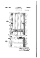
- Figure 1 is a top plan view' of the expander unit
- Figure 2 is a section taken on line 2-2 of Figure l;
- Figure 3 is a section taken on line 33 of Figurel.
- Figure 4 is a section taken on line 4 4 of l Figure 1;
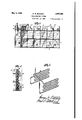
- Figure 5 is a perspective showing the arrangement of the coils.
- FIG. 1 a refrigerating expander unit of the type similar to that used in ordinary household refrigerators.
- This embodment comprises generally a main casing 1 bounded by four walls 2, 3, 4 and 5, and having a shelf 6 integral therewith.
- the bottom wall 5 and the shelf 6 are adapted to hold trays for making ice, frozen desserts, and the like.
- the top wall 3 is provided with a plurality of longitudinal radiating ribs 7 and a pluralityfof transverse radiating ribs 8 and 9.
- The-radiating ribs 9 are spaced so as to conjointly define with the wall 3 a trough 10, which constitutes part of the coil chamber hereinafter described.
- shell members 11 and 12 Secured to the maincasing 1 are twoside shell members 11 and 12 which are provided with a plurality of transverse radiating ribs 13 and which have vent holes 18 for the purpose hereinafter referred to. These shell members 11 and 12 are provided with bosses 13 having tapped bores 14 therethrough. These tapped bores 14 register with the tapped bores 15 in the bosses 16 which are integral with the main casing 1. The shells 11 and 12 are secured to the casing 1 by means of screws 17 passing through the corresponding bosses.
- the side shells 11 and 12 are so constructed and associated with the casing 1 as to con' jointly define hollow walls. These hollow walls constitute chambers 19 and 20 for the.
- the coils 21 are placed aroundthe mam caslng 101 and the side shells 11 and 12 are screwed in place.
- the organization is then preheated and the molten metal, having a melting point which is preferably lower than the melting point of themetal that it comes in contact'with, is poured into the coil chambers 19 and 20 through the trough 10.
- This molten metal may be lead, zinc, tin, and the like, although lead is preferred.
- the air is permitted to escape through the vents 18 while the pouring process is progressing. These vents also act as overflow openings for the molten lead.
- the -present invention has been concretely exemplified in the form of a refrigerating expander unit, but it is obvious that it can be adapted to any device whose function resides in conveying heat from one medium to another.
- An expander unit of the class described comprising a main casing having top, bot! tom and side walls which define a cooling chamber, "radiating ribs associated with said ca smg, a palr of said ribs conjointly deflning w1th sald top wall a trough, shells associated with said main lcasing and forming C5l hollow walls therewith, an expansion coil serpentined in said hollow wall and extending along said trough, and a filling of metal occupying the intervening spaces in said 2.
- expander unit of the rclass described comprislng a main casing having top, bottom and side walls which define a coolingv chamber, radiating ribs associated with said vwith said main casing and forming hollow walls therewith, an expansion coil serpentined in said hollow lwall and extending along said trough, and a filling of lead occupying the intervening spaces in said wall and trough.
- a refrigerator expander unit of the -cla ⁇ ss described comprising a casing having a hollow wall, a filling of metal in said wall,
- a refrigerator expander unit of the class described comprising a casing having a hollow wall, a filling of lead in said wall, and an expansion coil embedded in said lead filling, one side of said wall being corrugated to substantially conform with the contour of ⁇ said coil.
Landscapes
- Engineering & Computer Science (AREA)
- Physics & Mathematics (AREA)
- Mechanical Engineering (AREA)
- Thermal Sciences (AREA)
- General Engineering & Computer Science (AREA)
- Heat-Exchange Devices With Radiators And Conduit Assemblies (AREA)
Description
May 3, 1932. G. w. BUNGAY vMFR:mawrmavsxfs'x'fzu Filed Dec. 10, 1929 ZSheets-Sheot 1 IVM.
May 3, 41932- G. w. BUNGAY 1,856,536
REFRIGERATIKG SYSTEM Filed DML-10. 19,29 2 Sheets-Sheet 2 8 y 9 fa 9 l,z5A "fly ,7 l I will l .u will" IH 22 i" II :Il 1
I ENTOR ATTORNEY Patented May 3, 1932 UNITED STATES PATENT OFFICE GEORGE W. BUNGAY, OF PLAINEIELD, NEW JERSEY, ASSIGNOR TO ALUMINUM COMj PANY OF AMERICA, OF PITTSBURGH, PENNSYLVANIA, A CORPORATION OF PENN- SYLVLNIA REFRIGERATING SYSTEM Application led December 10, 1929'. Serial No. 412,953.
rlFhis invention relates to the art of refrigeration, and more particularly to a new and improved refrigerating expander unit and the mode of constructing the same.
The invention provides a simple and inexpensive process, whereby the expansion coils of a refrigerating expanding unit are embedded in a metallic wallf of said unit, thereby interposing an effective conducting medium between the coils and the cooling chamber thereof.
According to the present invention, the elements of the units are assembled, so as to dene a hollow wall, with the expansion coils positioned in the coil chamber constituted by said wall. This organization is then preheated, and a suitable molten metal poured into said coil chamber so as to envelope said coils and lill the intervening spaces with said metal. In this manner a unit is constructed which is simple and eiiicient as well as inexpensive.
Various other features and advantages of the invention will be apparent from the following particular description and from an inspection of the accompanying drawings.
Although the novel features which are believed to be, characteristic of this invention Will be particularly pointed out in the claims appended hereto, the invention itself, as to its objects and advantages, the mode of its operation and the manner of its organization may be better understood by referring to the following description taken in conection with the accompanying drawings forming a part thereof, in which:
Figure 1 is a top plan view' of the expander unit;
Figure 2 is a section taken on line 2-2 of Figure l;
Figure 3 is a section taken on line 33 of Figurel.; f
Figure 4 is a section taken on line 4 4 of l Figure 1; and
Figure 5 is a perspective showing the arrangement of the coils.
Like reference characters denote like parts in the several figures of the drawings. A In the following description and in the claims parts will be identified by specific names for convenience, but they are intended to be as generic in their application to similar parts as the art will permit.
rllie following drawings exemplify the adaptation of the present invention to a refrigerating expander unit of the type similar to that used in ordinary household refrigerators. This embodment comprises generally a main casing 1 bounded by four walls 2, 3, 4 and 5, and having a shelf 6 integral therewith. The bottom wall 5 and the shelf 6 are adapted to hold trays for making ice, frozen desserts, and the like. The top wall 3 is provided with a plurality of longitudinal radiating ribs 7 and a pluralityfof transverse radiating ribs 8 and 9. The-radiating ribs 9 are spaced so as to conjointly define with the wall 3 a trough 10, which constitutes part of the coil chamber hereinafter described. Secured to the maincasing 1 are twoside shell members 11 and 12 which are provided with a plurality of transverse radiating ribs 13 and which have vent holes 18 for the purpose hereinafter referred to. These shell members 11 and 12 are provided with bosses 13 having tapped bores 14 therethrough. These tapped bores 14 register with the tapped bores 15 in the bosses 16 which are integral with the main casing 1. The shells 11 and 12 are secured to the casing 1 by means of screws 17 passing through the corresponding bosses.
The side shells 11 and 12 are so constructed and associated with the casing 1 as to con' jointly define hollow walls. These hollow walls constitute chambers 19 and 20 for the.
reception of theexpanding coils 21 through which a sui-table refrigerant is conducted. These coils lead into the chamber 19 through an opening 22 in the shell 11 and are serpensurface as well as minimizing the amount of metallic filling in the coil chambers 19 and 20.
In assembling the elements ofthe unit the coils 21 are placed aroundthe mam caslng 101 and the side shells 11 and 12 are screwed in place. The organization is then preheated and the molten metal, havinga melting point which is preferably lower than the melting point of themetal that it comes in contact'with, is poured into the coil chambers 19 and 20 through the trough 10. This molten metal may be lead, zinc, tin, and the like, although lead is preferred. The air is permitted to escape through the vents 18 while the pouring process is progressing. These vents also act as overflow openings for the molten lead. l
It should be noted that through the process as described a novel means has been created for interposing a metallic conducting agent between the expanding coils and-the cooling chamber.. It should also be observed that by embedding the expanding coils in a metallic filling instead of a solid metallic wall, the costly `process of sand-casting is obviated.
The -present invention has been concretely exemplified in the form of a refrigerating expander unit, but it is obvious that it can be adapted to any device whose function resides in conveying heat from one medium to another.
Althoughcertain novel features of the invention have been shown and described and are pointed out in the annexed claims, it will be understood that various omissions, sub-- stitutions and changes in the several steps of y the process and in 'its operation and in the form and details of the apparatus illustrated may be made by those skilled in the art without departing from the spirit of the inven- 'wall and trough.
tion.
I claim: l. An expander unit of the class described comprising a main casing having top, bot! tom and side walls which define a cooling chamber, "radiating ribs associated with said ca smg, a palr of said ribs conjointly deflning w1th sald top wall a trough, shells associated with said main lcasing and forming C5l hollow walls therewith, an expansion coil serpentined in said hollow wall and extending along said trough, and a filling of metal occupying the intervening spaces in said 2. expander unit of the rclass described comprislng a main casing having top, bottom and side walls which define a coolingv chamber, radiating ribs associated with said vwith said main casing and forming hollow walls therewith, an expansion coil serpentined in said hollow lwall and extending along said trough, and a filling of lead occupying the intervening spaces in said wall and trough.
3. A refrigerator expander unit of the -cla\ss described comprising a casing having a hollow wall, a filling of metal in said wall,
in said metal {illan expansion coill embedded' in said metal filling, one side of said wall being corrugated f' to substantially conform with the contour of said coil.
5. A refrigerator expander unit of the class described comprising a casing having a hollow wall, a filling of lead in said wall, and an expansion coil embedded in said lead filling, one side of said wall being corrugated to substantially conform with the contour of`said coil.
In testimony-whereof, I have aixed my signature to this specification.
GEORGE WALDEMAR BUNGAY.
i loo casing, a pair of said ribs conjointly defining f with sald tpfwall' a trough, shells associated
Priority Applications (1)
| Application Number | Priority Date | Filing Date | Title |
|---|---|---|---|
| US412953A US1856536A (en) | 1929-12-10 | 1929-12-10 | Refrigerating system |
Applications Claiming Priority (1)
| Application Number | Priority Date | Filing Date | Title |
|---|---|---|---|
| US412953A US1856536A (en) | 1929-12-10 | 1929-12-10 | Refrigerating system |
Publications (1)
| Publication Number | Publication Date |
|---|---|
| US1856536A true US1856536A (en) | 1932-05-03 |
Family
ID=23635153
Family Applications (1)
| Application Number | Title | Priority Date | Filing Date |
|---|---|---|---|
| US412953A Expired - Lifetime US1856536A (en) | 1929-12-10 | 1929-12-10 | Refrigerating system |
Country Status (1)
| Country | Link |
|---|---|
| US (1) | US1856536A (en) |
Cited By (1)
| Publication number | Priority date | Publication date | Assignee | Title |
|---|---|---|---|---|
| US3011323A (en) * | 1957-10-23 | 1961-12-05 | Carbonic Dispenser Inc | Ice plate |
-
1929
- 1929-12-10 US US412953A patent/US1856536A/en not_active Expired - Lifetime
Cited By (1)
| Publication number | Priority date | Publication date | Assignee | Title |
|---|---|---|---|---|
| US3011323A (en) * | 1957-10-23 | 1961-12-05 | Carbonic Dispenser Inc | Ice plate |
Similar Documents
| Publication | Publication Date | Title |
|---|---|---|
| US2127286A (en) | Apparatus for transferring heat | |
| US1856536A (en) | Refrigerating system | |
| US2511851A (en) | Two temperature refrigerator | |
| US2332336A (en) | Elastic fluid condenser | |
| US2250648A (en) | Refrigerating apparatus | |
| US2589551A (en) | Two-temperature refrigerator | |
| US2311947A (en) | Refrigerating apparatus | |
| US2391507A (en) | Refrigerating apparatus | |
| US1821754A (en) | Air cooled condenser for refrigerating systems | |
| US2509610A (en) | Refrigerating apparatus | |
| US2112733A (en) | Transformer | |
| US1812102A (en) | Refrigerator | |
| US2669853A (en) | Refrigerated cabinet having movable condenser | |
| US2188893A (en) | Refrigerating apparatus | |
| US2432931A (en) | Refrigerated evaporator shelf | |
| US2438114A (en) | Refrigerator construction | |
| US1967106A (en) | Condenser for refrigerating machines | |
| US2076277A (en) | Apparatus for refrigerating | |
| US2509612A (en) | Refrigerating apparatus | |
| US1922091A (en) | Refrigerating apparatus | |
| US2012704A (en) | Refrigerant compressing apparatus | |
| US2878653A (en) | Refrigerated display case | |
| US2012892A (en) | Refrigerating method and apparatus | |
| US2169201A (en) | Refrigerator construction | |
| US1957955A (en) | Refrigerator cabinet with |