US1856535A - Caster stem and socket - Google Patents
Caster stem and socket Download PDFInfo
- Publication number
- US1856535A US1856535A US407312A US40731229A US1856535A US 1856535 A US1856535 A US 1856535A US 407312 A US407312 A US 407312A US 40731229 A US40731229 A US 40731229A US 1856535 A US1856535 A US 1856535A
- Authority
- US
- United States
- Prior art keywords
- stem
- plate
- cap
- socket
- arms
- Prior art date
- Legal status (The legal status is an assumption and is not a legal conclusion. Google has not performed a legal analysis and makes no representation as to the accuracy of the status listed.)
- Expired - Lifetime
Links
- 238000010276 construction Methods 0.000 description 12
- 230000015572 biosynthetic process Effects 0.000 description 4
- 238000000926 separation method Methods 0.000 description 4
- 238000004873 anchoring Methods 0.000 description 3
- 238000006073 displacement reaction Methods 0.000 description 2
- 238000012986 modification Methods 0.000 description 2
- 230000004048 modification Effects 0.000 description 2
- 230000003014 reinforcing effect Effects 0.000 description 2
- ONIBWKKTOPOVIA-BYPYZUCNSA-N L-Proline Chemical compound OC(=O)[C@@H]1CCCN1 ONIBWKKTOPOVIA-BYPYZUCNSA-N 0.000 description 1
- 241000306729 Ligur Species 0.000 description 1
- 241001446467 Mama Species 0.000 description 1
- 238000010411 cooking Methods 0.000 description 1
- 210000005069 ears Anatomy 0.000 description 1
- 239000002184 metal Substances 0.000 description 1
- 230000002787 reinforcement Effects 0.000 description 1
- 230000000717 retained effect Effects 0.000 description 1
- 238000005406 washing Methods 0.000 description 1
Images
Classifications
-
- B—PERFORMING OPERATIONS; TRANSPORTING
- B60—VEHICLES IN GENERAL
- B60B—VEHICLE WHEELS; CASTORS; AXLES FOR WHEELS OR CASTORS; INCREASING WHEEL ADHESION
- B60B33/00—Castors in general; Anti-clogging castors
- B60B33/0002—Castors in general; Anti-clogging castors assembling to the object, e.g. furniture
Definitions
- the invention relates to a caster construction including the socket and stem.
- the chief object of the invention is to provide a relatively non-cooking stem supporting socket adapted to support a tubular leg and arranged such that clicking of the stem in the socket is substantially eliminated whether the stem be permanently or detachably mounted in the socket.
- the chief feature of the invention consists in first, the particular construction of the frame comprising the socket, whereby a top bearing is obtained, and second, the nonclicking end of the stem head associated therewith.
- Fig. 1 is a central sectional view through a tubular leg and caster socket, the caster being shown in elevation.
- Fig. 2 is a similar view of a modified form, parts of the caster being omitted.
- Fig. 3 is a similar view of a further modified form.
- Figs. 4 and 5 are similar views and illustrate further modified forms of the invention.
- Fig. 6 is a transverse sectional view taken on the line 6-6 of Fig. 4 and in the direction of the arrows.
- Fig. 7 is an off-center longitudinal section taken on the line 7-7 of Fig. 6 and in the direction of the arrows.
- Fig. 8 is a view similar to Figs. 2 to 5, inclusive, and of a modified form of the invention.
- Fig. 1 is a central sectional view through a tubular leg and caster socket, the caster being shown in elevation.
- Fig. 2 is a similar view of a modified form, parts of the caster being omitted
- Fig. 9 is a similar view of a modified form thereof.
- Fig. 10 is an elevational view of one form of stem portion provided with relatively permanent connecting means.
- Fig. 11 is a similar view of a modified form illustrating one form of detachable connection'.
- Fig. 12 is an end elevationwith parts in central section to show the same and other parts in detail and of the head of the end of the stem showing the anticlicking construction.
- Fig. 13 is a top plan view thereof.
- Fig. 14 is a view similar to Fig. 12 'and of a modiied form of the anticlicking invention.
- Fig. 15 is a top plan view thereof.
- Fig. 16 is a central sectional view of a modified form of the invention and constitutes the preferred form.
- Fig. 17 is a transverse sectional view taken on line 17-17 of Fig. 16 in the direction of the arrows.
- 2O indicates a tubular leg, which is supported by a load supporting plate in turn supporting a stem receiving frame comprising an inverted U-shaped spring frame, the central p0rtion of which is apertured to receive a cup construction providing a top bea-ring for a caster stem.v
- the caster stem extends through a central opening in said supporting plate and is secured to a horn 21, the ends of which are turned angularly to form parallel ears 22 that support a pivot 23 rotatably mounting a caster roller 24.
- the stem indicated'generally by the numeral 26, includes an enlargement 27 adjacent its lower end and an enlargement 28 in spaced relation therewith Vbetween which is mounted the horn 21, see Fig. 8.
- the stem may be detachably associated with the socket and one form of detachable connection is illustrated in Fig. 11 wherein the stem is gro'oved as at 227 to receive a split outwardly expansible stem retaining ring 228, the same being compressible into nested relation within the groove to permit passage of the stem through the central stem receiving opening in the load supporting plate.
- Other equivalent forms of detachable anchorage may be provided as is well known in the art.
- FIG. 10 One form of permanent stem and socket connection is illustrated in Fig. 10 wherein stem 126 is provided with one or more lateral enlargements 128, struck therefrom, said enlargements being spaced above the upper horn plate anchoring portion. When mounted in the socket said enlargements lie immediately above the load supporting plate.
- the position of the ring 228 or the enlargements 128, relative to the horn plate anchoring portion is such that limited aXial movement of the stem relative to the load supporting plate is permitted but such movement is not sufficient to permit lateral escapement of the upper end of the stem from the laterally centering and top bearing cap.
- the caster stem particularly in movement over an uneven floor or off and onto rugs,
- an anti-clicking construction is provided and interposed between the end of vthe casterstein andthe supporting top" f bearing, so' that ythe 'end ofthe stem-or a ing-an inturned retaining collar portion 230.
- vSlidable in said recess is a plunger 231 of a ydiameter slightly less than that of the retainingcollar portion 230.
- the end 232 of the plunger is preferably'formed as a portion of the surface ofthe sphere so lthat when the Yplunger is fully retracted and seated in the socket, said partial spherical surface forms a continuation kof the partial spherical or .hemi-spherical yhead of the stem, same being indicated at 233 and Figs. 12 and 13.
- the vplunger 231 withinr the recess is enlarged and includes a headportion 234 which bears upon therecess enclosed spring 235 which normallyprojects the plunger outwardly and main-VA tains the samein constant engagement withV .the cap when the stem is associated with the socket.
- Figs. 14 and 15 illustrate a modified form of anti-rattling construction.
- Stem 326 includes the coaxial bore 329which is reduced by the retaining collar forming portion 330 in turn retaining the plunger 331y against Vcomplete separation by Vretaining the recessed .receivable head portion 334 which bears against the recess enclosed Aspring 335.
- Spring335 normally projects the plunger outwardly to maintain constant engagement Ybetween the cap and stem when the stem is associated with the socket. Y.
- Figs. 1 to 9 and Figs. 16 and 17 there are illustrated various forms of sockets with which the caster stem constructions illustrated in Figs. 10 to 15 may be associated.
- the inverted U-shaped spring frame has its side or arm portion curved in transverse section so that a somewhat cylindrical approximation is obf c chamber and forms a collar 43.
- Mounted in the central openingV 42 is a cap having the heini-spherical head portion 44 and cylindrical bodyvportion 45, the former projecting above the plane of the ⁇ arm Yconnecting portion 41 and the latter being concentrically mounted within the opening 42 and the cylindrical collar 43 defining the same.
- the cap 44 includes a lateral portion 46 that bears upon the end of the collar'portion 43.
- Thelateral portion 46 herein serves as a stop and prevents axial separation ofthe cap and arm connecting portion of the socket, and is also turned backtoform a groove 47 with the cylindrical portion 45 and into'which the collar portion 42 projects.V
- the load sustaining plate 5() is provided .1 Vwith the down turned flange or skirt 51, al-
- the central portion of thel plate 50 is .raised or embossed as at 52 and central- L lyl apertured as atv 53 for-'receiving stem 26.
- a pair of diametrically positioned apertures 54 is provided.
- the laterally reduced ends55 of the arms extend through said apertures, turned inwardly as at 56 and terminate short of stem engagement but may, if desired, partiallyembrace .said stem, as indicatedat 57.Y
- the cap and arm connecting portions are. illustrated'in a simplified form.
- the inverted U-shaped spring socket forming arms 140 are shown ⁇ barrel ,shaped and are connected at their upper endsby the plate portion 141, the latter beingcentrally apertured as at 142 and herein the aperture defining collar portion 143 is extended upwardly instead of downwardly,fas shown in Fig. 1.
- The-cap 144 of hemi-spherical formation is soV .mounted in the apertureV and collar'by the i? f reinforcing ornamental skirt flange 151.
- the central portion of said plate is embossed or offset as at 152 and centrally aperture'd as at 153 toV receive the stem 26. rhe aperture is defined by down turned collar 156.
- the intermediate portion. connecting the plate andthe embossed central portion is diametrically slotted as at 154, and extending through the slots and in a plane intermediate planes of the embossment and the plate, are the inturned arms anchoring portions 156, which if desired, may partially embrace the collar portion 154 as illustrated at 57 in Fig. 1.
- the cap and frame connection is substantially identical to that illustrated in Fig. 1 and similar numerals of the 200 series indicate like parts, thus 240 the spring frame arms, 241 the centrally connecting portion, 242 the central aperture therein, 243 the aperture defining collar, 244 the heini-spherical portion of the cap, 245 the cylindrical portion mounted within the aperture and collar, 246 the lateral cap limiting portion and 247 the groove forming portion receiving the collar 243.
- the lower ends of the arms are secured to the load supporting plate 250 provided with the down turned ornamental and reinforcing flange 251.
- the plate 250 centrally apertured as at 253 and provided with a collar portion 254, extends upwardly therefrom, thence outwardly as at 252 and thence downwardly as at 259, forming a groove that receives the upturned ends 256 of the inturned portions 255 of' the arms 240.
- Figs. 1 and 3 the spring frame is adjustable to tubular leg dia-meter by lateral elongation
- Fig. 2 illustrates a form wherein tubular leg adjustment is obtained by lateral extension of the arms and not necessarily by axially elongation thereof, as required by the forms illustrated in Figs. 1 and 3.
- Fig. 4 the simplest form of cap and frame connection is illustrated and the arms 340 are connected by the top portion 341, centrally apertured at 342 to receive the cap comprising the hemi-spherical portion 344 and the cylindrical portion 345.
- the cap is retained in the socket frame against axial displacement by the lateral portion 346.
- a detachable type which, in addition thereto, is adjustable td the tubular leg by lateral enlargement only and is illustrated in Figs. 4, 6 and 7.
- plate 350 is provided with the downturned skirt 351.
- Each of the barrel arms 340 includes a reduced lower portion 355, receivable by a T-shaped slot 354, two thereof being provided and diametrically positioned, see Fig. 6.
- the reduced portion 355 is enlarged kas at 356 and serves as a retaining portion.
- a T-shaped enlargement may be substitnted for the wedge shape illustrated.
- the plate 350 is provided with va central aperture 353 that receives stem 26.
- the spring frame is detachably associated with the load supporting plate by the enlarged portion 356, passing through the laterally enlarged portion or head of the Tshaped slot.
- the spring arms then are compressed towards each other until the lateral enlargements underlie the plate portion adjacent the main portion of each slot to lock the plate and arms together.
- FIG. 5 A modified form of plate and frame anchorage is illustrated in Fig. 5.
- 'Ihe plate 450 is skirted as at 451 and is centrally apertured as at 453, said aperture being defined by the upwardly directed collar 458.
- 'Ihe barrel shaped frame arms 440 extend inwardly and a laterally reduced portion 455 of each extends vertically through one of a pair of a diametrically positioned radially elongated slots 454 in plate 450.
- the lower free ends ot said arms are turned laterally and Outwardly as at 456 and permanently unite the frame to the plate. Adjustment of the socket to the tube 2O is obtained by the arms moving towards and away from each other in the radially elongated slots 454.
- the spring frame 'arm construction 450 is substantially cylindrical in outline.
- the top portion 541, connecting the upper ends of said arms, is centrally apertnred as at 542, the aperture being defined by an upturned collar 543.
- the hemi-spherical cap 544 includes this cylindrical portion 545, positioned within the aperture and collar.y Said cap extends an appreciable disstance, see 549, into the chamber formed within the spring frame and then is turned back outwardly and upwardly into a conical formation 547, the edge 546 of which bears upon the top portion 541 and prevents axial separation of the cap and frame.
- the plate 550 in this form of the invention is provided with annpturned leg mount 551, telescopically receiving the end of the tubular leg- 220.
- rlhe plate 550 is provided with ra dially elongated diametrically positioned apertures 554, through which reduced vertical extensions 555 of the armextend and then are turned laterally and inwardly as at 556 to lock the frame and plate together.
- the plate includes the central aperture
- the cylindrical formation is reduced to a strap formation 555 at the laterally offset portion 559 positioned parallel to and immediately above the plate 550.
- thehemi-spherical cap 1644 including lthe :cylindrical vportion V645, which extends;into the chamber formed with inthe Spring'fram-e Iarms .1an.appreciable .distance. fllhecap .is turned back upon itself :as ,fati64e7 and fthe-enveloping vtubular 'construction'61l7 ypreferably isprovided with an outwardly and .laterally ldirectedflange 646, which abears 'upon the top 641 ⁇ and prevents .axialfseparation ofthe-cap .and frame.
- V645 the hemi-spherical cap 1644 including lthe :cylindrical vportion V645, which extends;into the chamber formed with inthe Spring'fram-e Iarms .1an.appreciable .distance. fllhecap .is turned back upon itself :as ,fati64e7
- the arms 740 ⁇ are shown .cylindrical although V'they maybe barrel-shaped.
- the cylindrical portion 7 f5 is elongated :as at 749, and lprojects inwardly a considerable distance'into the rchamber included y'within the fram-e arms. ⁇ f
- a supporting frame including ahorizontally disposed plate having 'an aperture, a collar integral with and projecting beyond said plate and surroundinglsaid aperture, an elongated tubular cap having a closed upper end, said cap having its lower lopen end projecting through said aperture anddisposed an appreciable distance below said plate to snugly embrace the upper porti-on of a caster pintle, and an outwardly directed annular portion integral with said cap disposed an appreciable distance from the ends ofthe latterjtointerengage throughoutits circumference with said collarto limit the movement of the cap in said aperture.
- v'libe-plate ⁇ 750 is prol vvided with a down-turned lskirtl and is :centrally .apertured as at 743, said aperture 'being definedby downwardly directed col- Y in the load supporting plate.
- v.larf758- rllhe plate is provided with a pair fof radially elongatedslots 745,-each of which receives a vertically v'directed extension 7 55 .of the cylindrically shaped spring arms and said extensions are turned laterally and inwardly as at7 56.
- the plate 750 is provided with -a pair of arcuate emloossmentsY 7 52, which serve as reinforcements and also .v
- a supporting frame including a horizontally disposed plate having an aperture, a collar Vintegral with Y
Landscapes
- Engineering & Computer Science (AREA)
- Mechanical Engineering (AREA)
- Closures For Containers (AREA)
Description
May 3, 1932. E. A. BRoKAw E'r Al.
CASTER STEM AND SOCKET Fired Nov. 15. 1929 ATTORNEYS.
.lll
t l l INVENTQRS. fair/mp Ko/f/vu/.j W/u /HM b. on UNG.
Mama( 1155.5 za U v 74345 75l- E IGI El. lf3- @a FIEI Patented May 3, 1932 9 Unirse sraras vPATENT OFFIQE yEDXARD BROKAW AND WILLIAM I-I. NOELTING, OF EVANSVILLE, INDIANA, AS- l SIGNORS TO FAULTLESS @ASTER COMPANY, F EVANSVILIE, INDIANA, A COR- PORATION Application filed November 15, 1929. Serial No. 407,312.
The invention relates to a caster construction including the socket and stem.
The chief object of the invention is to provide a relatively non-cooking stem supporting socket adapted to support a tubular leg and arranged such that clicking of the stem in the socket is substantially eliminated whether the stem be permanently or detachably mounted in the socket.
The chief feature of the invention consists in first, the particular construction of the frame comprising the socket, whereby a top bearing is obtained, and second, the nonclicking end of the stem head associated therewith.
The full nature of the invention will be understood from the accompanying drawings and the following description and claims:
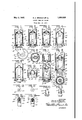
Fig. 1 is a central sectional view through a tubular leg and caster socket, the caster being shown in elevation. Fig. 2 is a similar view of a modified form, parts of the caster being omitted. Fig. 3 is a similar view of a further modified form. Figs. 4 and 5 are similar views and illustrate further modified forms of the invention. Fig. 6 is a transverse sectional view taken on the line 6-6 of Fig. 4 and in the direction of the arrows. Fig. 7 is an off-center longitudinal section taken on the line 7-7 of Fig. 6 and in the direction of the arrows. Fig. 8 is a view similar to Figs. 2 to 5, inclusive, and of a modified form of the invention. Fig. 9 is a similar view of a modified form thereof. Fig. 10 is an elevational view of one form of stem portion provided with relatively permanent connecting means. Fig. 11 is a similar view of a modified form illustrating one form of detachable connection'. Fig. 12 is an end elevationwith parts in central section to show the same and other parts in detail and of the head of the end of the stem showing the anticlicking construction. Fig. 13 is a top plan view thereof. Fig. 14 is a view similar to Fig. 12 'and of a modiied form of the anticlicking invention. Fig. 15 is a top plan view thereof.
Fig. 16 is a central sectional view of a modified form of the invention and constitutes the preferred form.
Fig. 17 is a transverse sectional view taken on line 17-17 of Fig. 16 in the direction of the arrows.
1n the drawings, 2O indicates a tubular leg, which is supported by a load supporting plate in turn supporting a stem receiving frame comprising an inverted U-shaped spring frame, the central p0rtion of which is apertured to receive a cup construction providing a top bea-ring for a caster stem.v The caster stem extends through a central opening in said supporting plate and is secured to a horn 21, the ends of which are turned angularly to form parallel ears 22 that support a pivot 23 rotatably mounting a caster roller 24.
The stem, indicated'generally by the numeral 26, includes an enlargement 27 adjacent its lower end and an enlargement 28 in spaced relation therewith Vbetween which is mounted the horn 21, see Fig. 8. The stem may be detachably associated with the socket and one form of detachable connection is illustrated in Fig. 11 wherein the stem is gro'oved as at 227 to receive a split outwardly expansible stem retaining ring 228, the same being compressible into nested relation within the groove to permit passage of the stem through the central stem receiving opening in the load supporting plate. Other equivalent forms of detachable anchorage may be provided as is well known in the art.
One form of permanent stem and socket connection is illustrated in Fig. 10 wherein stem 126 is provided with one or more lateral enlargements 128, struck therefrom, said enlargements being spaced above the upper horn plate anchoring portion. When mounted in the socket said enlargements lie immediately above the load supporting plate.
. The position of the ring 228 or the enlargements 128, relative to the horn plate anchoring portion is such that limited aXial movement of the stem relative to the load supporting plate is permitted but such movement is not sufficient to permit lateral escapement of the upper end of the stem from the laterally centering and top bearing cap.
The caster stem, particularly in movement over an uneven floor or off and onto rugs,
' does not have itsvend Aconstantly in contact with the cap so that the usual top bearing caster construction permits a clicking in the movement of the caster supported article,
.the same being the result of the intermittent Y `contact of the end of the stem with the cap.
When the caster'is' mounted in the hollow of a leg, particularly a tubular metal leg, such as illustrated `herein and which is general practice' in the washing machine trade, 'this v'clicking 'sound is Yintensified and resonatedl and is exceedingly objectionable;
`Accordingly, an anti-clicking construction is provided and interposed between the end of vthe casterstein andthe supporting top" f bearing, so' that ythe 'end ofthe stem-or a ing-an inturned retaining collar portion 230.
vSlidable in said recess is a plunger 231 of a ydiameter slightly less than that of the retainingcollar portion 230. The end 232 of the plunger is preferably'formed as a portion of the surface ofthe sphere so lthat when the Yplunger is fully retracted and seated in the socket, said partial spherical surface forms a continuation kof the partial spherical or .hemi-spherical yhead of the stem, same being indicated at 233 and Figs. 12 and 13. The vplunger 231 withinr the recess is enlarged and includes a headportion 234 which bears upon therecess enclosed spring 235 which normallyprojects the plunger outwardly and main-VA tains the samein constant engagement withV .the cap when the stem is associated with the socket. Y Y
Figs. 14 and 15 illustrate a modified form of anti-rattling construction. Stem 326 includes the coaxial bore 329which is reduced by the retaining collar forming portion 330 in turn retaining the plunger 331y against Vcomplete separation by Vretaining the recessed .receivable head portion 334 which bears against the recess enclosed Aspring 335. Spring335 normally projects the plunger outwardly to maintain constant engagement Ybetween the cap and stem when the stem is associated with the socket. Y. i V .In this formzof the inventionr the hemispherical end 333of the stein is reduced and a'hemi-spherical .shell 4 332 is carriedby the .end of the plunger 331.l Said shell is tele- Vscopically -associatedwith the -endof the stem and maybe hardened or the like.
In Figs. 1 to 9 and Figs. 16 and 17, there are illustrated various forms of sockets with which the caster stem constructions illustrated in Figs. 10 to 15 may be associated. In all of these forms of the invention the inverted U-shaped spring frame has its side or arm portion curved in transverse section so that a somewhat cylindrical approximation is obf c chamber and forms a collar 43. Mounted in the central openingV 42 is a cap having the heini-spherical head portion 44 and cylindrical bodyvportion 45, the former projecting above the plane of the `arm Yconnecting portion 41 and the latter being concentrically mounted within the opening 42 and the cylindrical collar 43 defining the same.
' The cap 44 includes a lateral portion 46 that bears upon the end of the collar'portion 43. Thelateral portion 46 herein serves as a stop and prevents axial separation ofthe cap and arm connecting portion of the socket, and is also turned backtoform a groove 47 with the cylindrical portion 45 and into'which the collar portion 42 projects.V
The load sustaining plate 5() is provided .1 Vwith the down turned flange or skirt 51, al-
though-the latter may, if desired, be omitted. yThis skirt however, increases the strength of the plate. The central portion of thel plate 50 is .raised or embossed as at 52 and central- L lyl apertured as atv 53 for-'receiving stem 26. At the merger between the pla-te 50 and the embossment 52, a pair of diametrically positioned apertures 54, is provided. The laterally reduced ends55 of the arms extend through said apertures, turned inwardly as at 56 and terminate short of stem engagement but may, if desired, partiallyembrace .said stem, as indicatedat 57.Y I
In Fig. 2, the cap and arm connecting portions are. illustrated'in a simplified form. The inverted U-shaped spring socket forming arms 140 are shown `barrel ,shaped and are connected at their upper endsby the plate portion 141, the latter beingcentrally apertured as at 142 and herein the aperture defining collar portion 143 is extended upwardly instead of downwardly,fas shown in Fig. 1. The-cap 144 of hemi-spherical formation is soV .mounted in the apertureV and collar'by the i? f reinforcing ornamental skirt flange 151. The central portion of said plate is embossed or offset as at 152 and centrally aperture'd as at 153 toV receive the stem 26. rhe aperture is defined by down turned collar 156. The intermediate portion. connecting the plate andthe embossed central portion is diametrically slotted as at 154, and extending through the slots and in a plane intermediate planes of the embossment and the plate, are the inturned arms anchoring portions 156, which if desired, may partially embrace the collar portion 154 as illustrated at 57 in Fig. 1.
It will be apparent, therefore, that the. plate and frame connection shown in F 1 may be employed with the cap and trame connection shown in Fig. 2 or vice versa. 'Ihe same interchangeability may be obtained with any of the subsequently described plate and frame, and cap and frame connections to form a complete socket.
In Fig. 3, the cap and frame connection is substantially identical to that illustrated in Fig. 1 and similar numerals of the 200 series indicate like parts, thus 240 the spring frame arms, 241 the centrally connecting portion, 242 the central aperture therein, 243 the aperture defining collar, 244 the heini-spherical portion of the cap, 245 the cylindrical portion mounted within the aperture and collar, 246 the lateral cap limiting portion and 247 the groove forming portion receiving the collar 243.
The lower ends of the arms are secured to the load supporting plate 250 provided with the down turned ornamental and reinforcing flange 251. The plate 250, centrally apertured as at 253 and provided with a collar portion 254, extends upwardly therefrom, thence outwardly as at 252 and thence downwardly as at 259, forming a groove that receives the upturned ends 256 of the inturned portions 255 of' the arms 240.
In Figs. 1 and 3, the spring frame is adjustable to tubular leg dia-meter by lateral elongation, while Fig. 2 illustrates a form wherein tubular leg adjustment is obtained by lateral extension of the arms and not necessarily by axially elongation thereof, as required by the forms illustrated in Figs. 1 and 3.
In Fig. 4, the simplest form of cap and frame connection is illustrated and the arms 340 are connected by the top portion 341, centrally apertured at 342 to receive the cap comprising the hemi-spherical portion 344 and the cylindrical portion 345. The cap is retained in the socket frame against axial displacement by the lateral portion 346.
Ak dierent type of plate and frame connection, to wit, a detachable type which, in addition thereto, is adjustable td the tubular leg by lateral enlargement only and is illustrated in Figs. 4, 6 and 7. In these ligures plate 350 is provided with the downturned skirt 351. Each of the barrel arms 340, includes a reduced lower portion 355, receivable by a T-shaped slot 354, two thereof being provided and diametrically positioned, see Fig. 6. The reduced portion 355 is enlarged kas at 356 and serves as a retaining portion.
a T-shaped enlargement may be substitnted for the wedge shape illustrated. The plate 350 is provided with va central aperture 353 that receives stem 26.
' In this form of the invention, the spring frame is detachably associated with the load supporting plate by the enlarged portion 356, passing through the laterally enlarged portion or head of the Tshaped slot. The spring arms then are compressed towards each other until the lateral enlargements underlie the plate portion adjacent the main portion of each slot to lock the plate and arms together.
A modified form of plate and frame anchorage is illustrated in Fig. 5. 'Ihe plate 450 is skirted as at 451 and is centrally apertured as at 453, said aperture being defined by the upwardly directed collar 458. 'Ihe barrel shaped frame arms 440 extend inwardly and a laterally reduced portion 455 of each extends vertically through one of a pair of a diametrically positioned radially elongated slots 454 in plate 450. The lower free ends ot said arms are turned laterally and Outwardly as at 456 and permanently unite the frame to the plate. Adjustment of the socket to the tube 2O is obtained by the arms moving towards and away from each other in the radially elongated slots 454.
In 8, the spring frame 'arm construction 450 is substantially cylindrical in outline. The top portion 541, connecting the upper ends of said arms, is centrally apertnred as at 542, the aperture being defined by an upturned collar 543. The hemi-spherical cap 544 includes this cylindrical portion 545, positioned within the aperture and collar.y Said cap extends an appreciable disstance, see 549, into the chamber formed within the spring frame and then is turned back outwardly and upwardly into a conical formation 547, the edge 546 of which bears upon the top portion 541 and prevents axial separation of the cap and frame.
The plate 550 in this form of the invention is provided with annpturned leg mount 551, telescopically receiving the end of the tubular leg- 220. rlhe plate 550 is provided with ra dially elongated diametrically positioned apertures 554, through which reduced vertical extensions 555 of the armextend and then are turned laterally and inwardly as at 556 to lock the frame and plate together. The plate includes the central aperture Herein the cylindrical formation is reduced to a strap formation 555 at the laterally offset portion 559 positioned parallel to and immediately above the plate 550.
'-.EigY Q .iill-'ustr-ates fa .modified .form of fcap and lframeconnecti'on wherein fthe 'frame :arms 640are connected :at their upper ends :by theiplate portion 641 centrally apertured iat 642, k:said aperture being :defined byv the v' .Yupwardlyextendingv .collar -portion 64.3.
Mounted therein, is thehemi-spherical cap 1644 including lthe :cylindrical vportion V645, which extends;into the chamber formed with inthe Spring'fram-e Iarms .1an.appreciable .distance. fllhecap .is turned back upon itself :as ,fati64e7 and fthe-enveloping vtubular 'construction'61l7 ypreferably isprovided with an outwardly and .laterally ldirectedflange 646, which abears 'upon the top 641 `and prevents .axialfseparation ofthe-cap .and frame. v
.iln'Figs '16 .and -17'the preferred form of he invention fis illustrated.' The arms 740 `are :shown .cylindrical although V'they maybe barrel-shaped. VThe upper vends :of the arms 'are-'connected by the plate portion 741, centnally .apertured at 7 42 and deiined by a downwardly directed collar '743 :and retains 'the cap .*against axial .separation from the .'firame. The cylindrical portion 7 f5 is elongated :as at 749, and lprojects inwardly a considerable distance'into the rchamber included y'within the fram-e arms.` f
.affixed our signatures.
upper portion Vof a caster pintle, .and @an .out-
Vthe movement k.of said icapiin said aperture.
2. In a 'caster construction, a supporting frame including ahorizontally disposed plate having 'an aperture, a collar integral with and projecting beyond said plate and surroundinglsaid aperture, an elongated tubular cap having a closed upper end, said cap having its lower lopen end projecting through said aperture anddisposed an appreciable distance below said plate to snugly embrace the upper porti-on of a caster pintle, and an outwardly directed annular portion integral with said cap disposed an appreciable distance from the ends ofthe latterjtointerengage throughoutits circumference with said collarto limit the movement of the cap in said aperture. Y
' In witness whereof, we have hereunto EDWARD AQBROKAW. WILLIAM v.No-ELTrive.
" v'libe-plate` 750, see Figs. 16 and 17, is prol vvided with a down-turned lskirtl and is :centrally .apertured as at 743, said aperture 'being definedby downwardly directed col- Y in the load supporting plate.
usf
v.larf758- rllhe plate is provided with a pair fof radially elongatedslots 745,-each of which receives a vertically v'directed extension 7 55 .of the cylindrically shaped spring arms and said extensions are turned laterally and inwardly as at7 56.
As shown clearly in Fig. 17, the plate 750 is provided with -a pair of arcuate emloossmentsY 7 52, which serve as reinforcements and also .v
serve as a leg centering device for the por- .tions between the two arms of the socket. The' adjustment of the socket to the tube is `obtained through lateral .displacement of the .arms inthe radially elongated slots provided While the invention has been described 'in great detail vin the foregoing specification, j
and various modifications thereof have been described herein, as well as illustrated in the drawings, said modifications, as well as those'V `which will readily suggest themselves to persons skilledin the art, all are considered to be within the broad purview of this invention,
reference being had to the appended claims.
The invention claimed is: 1. In a caster construction, a supporting frame including a horizontally disposed plate having an aperture, a collar Vintegral with Y
Priority Applications (1)
| Application Number | Priority Date | Filing Date | Title |
|---|---|---|---|
| US407312A US1856535A (en) | 1929-11-15 | 1929-11-15 | Caster stem and socket |
Applications Claiming Priority (1)
| Application Number | Priority Date | Filing Date | Title |
|---|---|---|---|
| US407312A US1856535A (en) | 1929-11-15 | 1929-11-15 | Caster stem and socket |
Publications (1)
| Publication Number | Publication Date |
|---|---|
| US1856535A true US1856535A (en) | 1932-05-03 |
Family
ID=23611487
Family Applications (1)
| Application Number | Title | Priority Date | Filing Date |
|---|---|---|---|
| US407312A Expired - Lifetime US1856535A (en) | 1929-11-15 | 1929-11-15 | Caster stem and socket |
Country Status (1)
| Country | Link |
|---|---|
| US (1) | US1856535A (en) |
-
1929
- 1929-11-15 US US407312A patent/US1856535A/en not_active Expired - Lifetime
Similar Documents
| Publication | Publication Date | Title |
|---|---|---|
| US1751691A (en) | Bracket | |
| US2312638A (en) | Theater seat hinge | |
| US1736177A (en) | Umbrella construction | |
| US3417956A (en) | Chair control | |
| US1856535A (en) | Caster stem and socket | |
| US2293144A (en) | Chair | |
| US570208A (en) | Convertible couch or settee | |
| US20240083307A1 (en) | Vertical latch locking mechanism for rotating seat | |
| US934005A (en) | Leg-mount caster. | |
| US1270350A (en) | Chair. | |
| US2631328A (en) | Caster | |
| US2486279A (en) | Swinging holder for card tables and the like | |
| US1906238A (en) | Top bearing adjustable and cushion frame for casters | |
| US2283062A (en) | Tilting chair mounting | |
| US1334496A (en) | Sliding shoe for furniture | |
| US2137335A (en) | Chair, seat, and the like | |
| US2987110A (en) | Adjustment locking device for chair base | |
| US543870A (en) | Ernest gustav hoffmann | |
| US1691716A (en) | Caster-mounting bracket | |
| US953492A (en) | Mounting for caster-wheels. | |
| US125350A (en) | Improvement in swiveled chairs | |
| US1731090A (en) | Gas burner | |
| US3868084A (en) | Swivel pedestal for seats | |
| US984824A (en) | Caster. | |
| US198186A (en) | Improvement in furniture-casters |