US1856527A - Air cleaner, crankcase ventilating means and the like - Google Patents
Air cleaner, crankcase ventilating means and the like Download PDFInfo
- Publication number
- US1856527A US1856527A US229651A US22965127A US1856527A US 1856527 A US1856527 A US 1856527A US 229651 A US229651 A US 229651A US 22965127 A US22965127 A US 22965127A US 1856527 A US1856527 A US 1856527A
- Authority
- US
- United States
- Prior art keywords
- air
- crankcase
- oil
- filter
- thru
- Prior art date
- Legal status (The legal status is an assumption and is not a legal conclusion. Google has not performed a legal analysis and makes no representation as to the accuracy of the status listed.)
- Expired - Lifetime
Links
- 239000000463 material Substances 0.000 description 31
- 239000003921 oil Substances 0.000 description 31
- 238000001914 filtration Methods 0.000 description 22
- 238000002485 combustion reaction Methods 0.000 description 12
- 239000000428 dust Substances 0.000 description 12
- 239000000314 lubricant Substances 0.000 description 11
- 239000000945 filler Substances 0.000 description 10
- 239000003595 mist Substances 0.000 description 9
- 239000004215 Carbon black (E152) Substances 0.000 description 7
- 230000005484 gravity Effects 0.000 description 7
- 229930195733 hydrocarbon Natural products 0.000 description 7
- 150000002430 hydrocarbons Chemical class 0.000 description 7
- 238000005406 washing Methods 0.000 description 4
- 239000012530 fluid Substances 0.000 description 3
- 239000002245 particle Substances 0.000 description 3
- 238000004140 cleaning Methods 0.000 description 2
- 239000000446 fuel Substances 0.000 description 2
- 239000007789 gas Substances 0.000 description 2
- 239000010687 lubricating oil Substances 0.000 description 2
- 229920006395 saturated elastomer Polymers 0.000 description 2
- 238000005266 casting Methods 0.000 description 1
- 230000006835 compression Effects 0.000 description 1
- 238000007906 compression Methods 0.000 description 1
- 238000001816 cooling Methods 0.000 description 1
- 238000000151 deposition Methods 0.000 description 1
- 238000010790 dilution Methods 0.000 description 1
- 239000012895 dilution Substances 0.000 description 1
- 238000004880 explosion Methods 0.000 description 1
- 238000010304 firing Methods 0.000 description 1
- 238000011010 flushing procedure Methods 0.000 description 1
- 239000007788 liquid Substances 0.000 description 1
- 239000002184 metal Substances 0.000 description 1
- 230000000717 retained effect Effects 0.000 description 1
- XLYOFNOQVPJJNP-UHFFFAOYSA-N water Substances O XLYOFNOQVPJJNP-UHFFFAOYSA-N 0.000 description 1
Images
Classifications
-
- F—MECHANICAL ENGINEERING; LIGHTING; HEATING; WEAPONS; BLASTING
- F02—COMBUSTION ENGINES; HOT-GAS OR COMBUSTION-PRODUCT ENGINE PLANTS
- F02M—SUPPLYING COMBUSTION ENGINES IN GENERAL WITH COMBUSTIBLE MIXTURES OR CONSTITUENTS THEREOF
- F02M35/00—Combustion-air cleaners, air intakes, intake silencers, or induction systems specially adapted for, or arranged on, internal-combustion engines
- F02M35/02—Air cleaners
- F02M35/04—Air cleaners specially arranged with respect to engine, to intake system or specially adapted to vehicle; Mounting thereon ; Combinations with other devices
-
- Y—GENERAL TAGGING OF NEW TECHNOLOGICAL DEVELOPMENTS; GENERAL TAGGING OF CROSS-SECTIONAL TECHNOLOGIES SPANNING OVER SEVERAL SECTIONS OF THE IPC; TECHNICAL SUBJECTS COVERED BY FORMER USPC CROSS-REFERENCE ART COLLECTIONS [XRACs] AND DIGESTS
- Y10—TECHNICAL SUBJECTS COVERED BY FORMER USPC
- Y10S—TECHNICAL SUBJECTS COVERED BY FORMER USPC CROSS-REFERENCE ART COLLECTIONS [XRACs] AND DIGESTS
- Y10S55/00—Gas separation
- Y10S55/19—Crankcase ventilation
-
- Y—GENERAL TAGGING OF NEW TECHNOLOGICAL DEVELOPMENTS; GENERAL TAGGING OF CROSS-SECTIONAL TECHNOLOGIES SPANNING OVER SEVERAL SECTIONS OF THE IPC; TECHNICAL SUBJECTS COVERED BY FORMER USPC CROSS-REFERENCE ART COLLECTIONS [XRACs] AND DIGESTS
- Y10—TECHNICAL SUBJECTS COVERED BY FORMER USPC
- Y10S—TECHNICAL SUBJECTS COVERED BY FORMER USPC CROSS-REFERENCE ART COLLECTIONS [XRACs] AND DIGESTS
- Y10S55/00—Gas separation
- Y10S55/28—Carburetor attached
-
- Y—GENERAL TAGGING OF NEW TECHNOLOGICAL DEVELOPMENTS; GENERAL TAGGING OF CROSS-SECTIONAL TECHNOLOGIES SPANNING OVER SEVERAL SECTIONS OF THE IPC; TECHNICAL SUBJECTS COVERED BY FORMER USPC CROSS-REFERENCE ART COLLECTIONS [XRACs] AND DIGESTS
- Y10—TECHNICAL SUBJECTS COVERED BY FORMER USPC
- Y10S—TECHNICAL SUBJECTS COVERED BY FORMER USPC CROSS-REFERENCE ART COLLECTIONS [XRACs] AND DIGESTS
- Y10S55/00—Gas separation
- Y10S55/30—Exhaust treatment
Definitions
- a further object of the invention is the provision of an air cleaning and crankcase ventilating means adapted to provide a draft of cool filtered air thru the crankcase of a hydrocarbon engine etc., thereby evaporating water and fuel dilution within the crankcase of said hydrocarbon engine.
- a further object of the invention is the provision of air cleaners in combination with the crankcase of a hydrocarbon engine etc., which serve also as a crankcase ventilating means and dustproof lubricant conveying ductsto the crankcase.
- a further object of the invention is the provision of air cleaners in combination with the crankcase of a hydrocarbon engine etc.,'
- a further provision of the present inven tion is an automatic means of adequately oilingthe filtering element of said air cleaners attached to the crankcase of said hydrocarbon engine, by' condensing the escaping vapors from the crankcase within the air cleaners.
- a still further object of the invention is the provision of a means of drawing a metered amount of filtered cool air thru the crankcase of a hydrocarbon engine etc., for
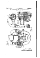
- Fig. 1 is a verticle section thru a conventional hydrocarbon engine illustrating the application of air cleaners to the crankcase, for the purpose of ventilating same with cool filtered air.
- Fig. 2 is a verticle section thru a modified form of the larger air cleaner shown at Fig. l-and illustrates a form of the invention suitable for filtering the air to the.
- Fig. 3 is a section on a reduced scale of the invention taken on the line 22 of Fig. 2.
- car uretor air supply is drawn by the pistons (not shown) of the engine 1 down thru air inlet pipe 2 thence into air cleaner 3 and up thru oily filtering material 4 and out thru clean air outlet 5. While it is true that oily fibrous air filtering material 4 causes only a sli ht resistance to the incoming air stream t is resistance is enough to cause a slight reduction of pressure at outlet of breather and lubricant filler pipe 6. This causes a slight outdraught of vapors from the crankcase thru opening 7.
- Cool filtered air is admitted to the crank case 8 of the engine 1 t T qualize the reduction of pressure within thru the smaller form of the invention 9 at air inlet 10, thence up-v wardly thru oily fibrous filtering material 11 and down to the crankcase thru dust roof lubricant conveyor duct and breather plpe 12 thru opening 13.
- the outdraught of vapor saturated air from the crankcase also carries a, slight amount of lubricating oil vapor. These vapors are carried out thru pipe 6, thru a wire fire screen and felt pad 14, over'its outlet.
- the purpose of the wire fire screen is to'prevent a backfire from the carburetor, from igniting the combustible crankcase vapors which if ignited would be liable to cause dangerous crankcase explosions.
- the purpose of the felt pad above the wire fire screen is to prevent an excess of lubricating oil vapors from being carried out of the crankcase and to provide a reservoir for storage of oil in the felt and alsoto carry the collected oil from the central portion of the air cleaner to the outer walls where it drains down to the filtering element 4, oiling and flushing same. Excess oil and collected dust etc. are retained in lower dust trap 15, from where they may be drained as occasion requires.
- the fibrous air filtering material 11 in the smaller inlet air cleaner 9 is oiled and flushed by condensed oily vapors which arise in breather duct 12 and are condensed by contact with the cool metal cover 16 after operating periods of the motor.
- any oil spilled either accidently or purposely over the edge of the breather and lubricant filler pipe 12 also serves to oil and flush the filtering element 11.
- a small dusty oil trap 17 and drain 18 is provided below to carry away condensed oily drippings, which in practice is found ample to thoroughly oil and flush the filtering element 11.
- Lubricant is added to the engine by simply removing either of the air cleaner covers and pouring it down the central dustproof lubricant filler and breather pipe 6 or 12.
- Fig. 2 illustrates a slightly modified form of the larger air cleaner 3, in which 19 is the air cleaner body, 20 is the clean air outlet, 21 indicatesa plurality of dusty air inlets, 22 is a removable dust and oil retainer cup, 23 is a filtering element composed of laminated wire screen disks held in compression by spool 24 and collar 25 on bolt 26.
- Bolt 26 is provided witha winged head 27'which provides a convenient and accessible means of removing the dust and oil retainer cup 22 and filtering element 23.
- 28 indicates the dustproof lubricant filler and breather duct located in the center of the air cleaner body 19.
- 29 is a flange serving to bolt pipe 30 to the crank case of an engine etc., to which the invention may be attached.
- Flange 29 and pipe 30 are preferably cast as shown, forming part of body casting 19.
- 31 is a wire fire screen and support for felt material .32 above.
- 33 is a metering orifice thru the felt material 32.
- '34 is the removable air cleaner cover.
- 35 indicates ribs for preventing the oil flowing down the walls of the cleaner from being drawn out of the clean air outlet 20.
- 36 indicates the air inlet of a conventional carburetor. During operation air drawn by the carburetor enters at openings 21, flows upwardly thru oily filtering element 23 and out thru clean air outlet 20. Resistance of filtering element 23 causes a slight drop of pressure at outlet of breather pipe 28.
- orifice 33 can be either varied in size or eliminated entirely to vapor, a vent for said crank case, an air filter protecting said vent, a filler pipe for said crank case, a main air intake, a conduit for said intake manifold, filtering means for said main intake, vapor condensing means above the filler, said intake manifold being arranged to, draw air through said main air intake and the filtering means therefor and also through the condensing means and the filler, said condensing means being arranged to draw condensed oil on to the filter in the main intake.
- an intake manifold a crank case containing oil vapor, an air cleaner for said intake manifold and means for condensing vapor from the crank case and for applying the condensate to the upper portion only of said cleaner, for oiling said cleaner by gravity.
- a crank case containing oil vapor containing oil vapor
- a vent for said crank case means for removing dust from any air entering said vent and means for condensing said vapor and applying the condensate to the upper portion of said dust removing means, whereby said condensate will flow by gravity over the lower portion ofsaid dust removing means.
- crank case containing fluid vapors and having an inlet and an outlet port, means for drawing air through said crank case, air washing means at said inlet port, and means for supplying the upper portion of said air washing means with condensed fluid from said crank case, whereby the remainder of said air washing means will be wet by said fluid by gravity.
- a cylinder a crank shaft, a piston adapted to be reciprocated within said cylinder for operating said shaft, a crank case for said shaft, means for supplying relatively cool filtered air to said case during the operation of said engine, a filter member for supplying filtered air to the intake passage of said engine, means for directing the filtered air from said crankcase to said filter member, and means for condensing oil vapors from said crankcase above said filter member whereby oil mist carried by said filtered air to said filter member will be condensed and fall by gravity on the upper portion of said filter material.
- an air cleaner containing filter material for cleaning the air supplied to said inlet, and means controlled by the suction of the engine for automatically removing oil from said crankcase and supplying the same to the upper portion only of the filter material whereby the remainder of the filter material will be oiled by gravity.
- an intake manifold an air inlet for said manifold, an air cleaner containing filter material for cleaning the air supplied to said inlet, and. means operative only during the operation of the engine for automatically Withdrawing oil mist from the crankcase and condensing the same abovesaid filter material for oiling the same by gravity.
- an internal combustion engine having a crankcase for containing oil, an intake manifold, an air intake for said manifold, an air cleaner in communication with said air intake, filter material within said cleaner forremoving dust from air passing therethrough to said intake, and means for automatically removing oil from said crankcase in the form of finely divided particles, condensing said particles to a liquid, and supplying the same to the upper surface only of said filter material duringthe operation of said engine.
- an air cleaner in communication with said air. intake, filter material within said cleaner for removing. dust from the air supplied to said intake through said filter, and a conduit for conducting oil and fuel vapors and mist from said crankcase to the upper portion only of said filter for oiling said filter material, the lighter volatile material being drawn into said intake by the engine suction.
- a filter device In an internal combustion engine provided with an air intake passage, a filter device, filter material within said device for filtering' the air passing through said passage, and means for supplying oil mist to the upper portion of said filter device and for condensing the same for automatically oiling said material.
- a filter for filtering air entering said passage, means for withdrawing volatile material and oil mist from the crank case of said engine, said volatile material being carried by air through said passage into said engine and said mist being supplied to the upper portion only of said filter for oiling the same, and for oiling the lower portion of said filter by gravity.
- a filter for filtering air entering said passage, means for supplying filtered air to the crank case of said engine, and means for causing said air to entrain oil mist and volatile material in said case and to deposit the oil on the upper portion of said filter, and to carry said volatile material through said passage into said engine.
- a filter member for said member for filtering the air entering said passage, an oil sump beneath said material and means for supplying oil mist from the crankcase to the top of said filter material for oiling the same and for washing foreign matter collected from the air by said material into said sump.
- an air filter for filtering the air entering said crankcase through said filler passage, a filter for filtering the air entering said intake passage, an air passage leading from said crankcase to said intake passage for conducting air from said crankcase to said intake passage and means in said air passage for removing oil mist therefrom and for preventing dust laden air from entering said crankcase said means constituting a flame arrest-er for preventing aback firing flame from entering said crank case.
- the purpose of 'the present invention is to afford means whereby the air entering a hydrocarbon engine, air compressor etc., may be cleaned and purified.
Landscapes
- Engineering & Computer Science (AREA)
- Chemical & Material Sciences (AREA)
- Combustion & Propulsion (AREA)
- Mechanical Engineering (AREA)
- General Engineering & Computer Science (AREA)
- Lubrication Details And Ventilation Of Internal Combustion Engines (AREA)
Description
y 1932- c. A. WINSLOVV 1,856,527
NG MEANS, AND THE LIKE jar) e2 07" Filed Oct. 29, 1927 AIR CLEANER, CRANKCASE VENTILATI Patented May 3, 1932 CHARLES A. WINSLOW, OF VALLEJO, CALIFORNIA Am CLEANER, CBANKCASE VENTILATING MEANS AND THE LIKE Application filed October 29, 1927. Serial No. 229,651.
A further object of the invention is the provision of an air cleaning and crankcase ventilating means adapted to provide a draft of cool filtered air thru the crankcase of a hydrocarbon engine etc., thereby evaporating water and fuel dilution within the crankcase of said hydrocarbon engine.
A further object of the invention is the provision of air cleaners in combination with the crankcase of a hydrocarbon engine etc., which serve also as a crankcase ventilating means and dustproof lubricant conveying ductsto the crankcase.
A further object of the invention is the provision of air cleaners in combination with the crankcase of a hydrocarbon engine etc.,'
adapted to draw a portion of the air to the cylinders, thru first, an air filter, thence thru the crankcase, and thence thru a second air filter to the cylinders of a hydrocarbon engine etc.
A further provision of the present inven tion is an automatic means of adequately oilingthe filtering element of said air cleaners attached to the crankcase of said hydrocarbon engine, by' condensing the escaping vapors from the crankcase within the air cleaners.
A still further object of the invention is the provision of a means of drawing a metered amount of filtered cool air thru the crankcase of a hydrocarbon engine etc., for
the purpose of cooling the lubricant within the crankcase and causing the heat from the lubricant together with the gases and vapors from the crankcase to be drawn thru the cylinders of a hydrocarbon engine and pumped out thru the exhaust with the exhaust gases.
Other objects and advantages will be evident and suggest themselves as the nature of the invention is more clearly understood.
In the accompanying drawings, Fig. 1 is a verticle section thru a conventional hydrocarbon engine illustrating the application of air cleaners to the crankcase, for the purpose of ventilating same with cool filtered air.
. Fig. 2 is a verticle section thru a modified form of the larger air cleaner shown at Fig. l-and illustrates a form of the invention suitable for filtering the air to the.
carburetor air supply, and causing an out draft from the crankcase of warm condensible vapors from the central dust proof lubricant filler pipe located in the center of the air cleaner, and is shown attached to the air 55 inlet of a conventional carburetor. The View is taken on the line indicated at 33 of the sectional View shown at Fig. 3.
Fig. 3 is a section on a reduced scale of the invention taken on the line 22 of Fig. 2.
as constituting a dustproof lubricant filler pipe and vapor condenser.
Referring to Fig. 1 of the drawin s, during operation of the invention car uretor air supply, is drawn by the pistons (not shown) of the engine 1 down thru air inlet pipe 2 thence into air cleaner 3 and up thru oily filtering material 4 and out thru clean air outlet 5. While it is true that oily fibrous air filtering material 4 causes only a sli ht resistance to the incoming air stream t is resistance is enough to cause a slight reduction of pressure at outlet of breather and lubricant filler pipe 6. This causes a slight outdraught of vapors from the crankcase thru opening 7.
Cool filtered air is admitted to the crank case 8 of the engine 1 t T qualize the reduction of pressure within thru the smaller form of the invention 9 at air inlet 10, thence up-v wardly thru oily fibrous filtering material 11 and down to the crankcase thru dust roof lubricant conveyor duct and breather plpe 12 thru opening 13.
As the cool filtered airenters the warm crankcase it naturally expands and absorbs the warm vapors of water and fuel dilution within and efi'ec'tively removes them thru opening 7 with the outdraught of saturated air from the crankcase.
The outdraught of vapor saturated air from the crankcase also carries a, slight amount of lubricating oil vapor. These vapors are carried out thru pipe 6, thru a wire fire screen and felt pad 14, over'its outlet. The purpose of the wire fire screen is to'prevent a backfire from the carburetor, from igniting the combustible crankcase vapors which if ignited would be liable to cause dangerous crankcase explosions. The purpose of the felt pad above the wire fire screen is to prevent an excess of lubricating oil vapors from being carried out of the crankcase and to provide a reservoir for storage of oil in the felt and alsoto carry the collected oil from the central portion of the air cleaner to the outer walls where it drains down to the filtering element 4, oiling and flushing same. Excess oil and collected dust etc. are retained in lower dust trap 15, from where they may be drained as occasion requires. The fibrous air filtering material 11 in the smaller inlet air cleaner 9 is oiled and flushed by condensed oily vapors which arise in breather duct 12 and are condensed by contact with the cool metal cover 16 after operating periods of the motor. However any oil spilled either accidently or purposely over the edge of the breather and lubricant filler pipe 12 also serves to oil and flush the filtering element 11. A small dusty oil trap 17 and drain 18 is provided below to carry away condensed oily drippings, which in practice is found ample to thoroughly oil and flush the filtering element 11. Lubricant is added to the engine by simply removing either of the air cleaner covers and pouring it down the central dustproof lubricant filler and breather pipe 6 or 12.
Fig. 2 illustrates a slightly modified form of the larger air cleaner 3, in which 19 is the air cleaner body, 20 is the clean air outlet, 21 indicatesa plurality of dusty air inlets, 22 is a removable dust and oil retainer cup, 23 is a filtering element composed of laminated wire screen disks held in compression by spool 24 and collar 25 on bolt 26. Bolt 26 is provided witha winged head 27'which provides a convenient and accessible means of removing the dust and oil retainer cup 22 and filtering element 23. 28 indicates the dustproof lubricant filler and breather duct located in the center of the air cleaner body 19. 29 is a flange serving to bolt pipe 30 to the crank case of an engine etc., to which the invention may be attached. Flange 29 and pipe 30 are preferably cast as shown, forming part of body casting 19. 31 is a wire fire screen and support for felt material .32 above. 33 is a metering orifice thru the felt material 32. '34 is the removable air cleaner cover. 35 indicates ribs for preventing the oil flowing down the walls of the cleaner from being drawn out of the clean air outlet 20. 36 indicates the air inlet of a conventional carburetor. During operation air drawn by the carburetor enters at openings 21, flows upwardly thru oily filtering element 23 and out thru clean air outlet 20. Resistance of filtering element 23 causes a slight drop of pressure at outlet of breather pipe 28. This reduction of pressure causes air and oily gaseous vapors to flow from the crankcase thru pipe 30 and up thru breather 28. These oily vapors continue to flow upwardly thru wire 31, felt material 32 and orifice 33 until they contact with cool cover 34 where all of the condensible "apors are condensed and flow down onto oil retaining felt material 32 and thence down the walls of the cleaner to the filtering element 23. It is found in practice that orifice 33 can be either varied in size or eliminated entirely to vapor, a vent for said crank case, an air filter protecting said vent, a filler pipe for said crank case, a main air intake, a conduit for said intake manifold, filtering means for said main intake, vapor condensing means above the filler, said intake manifold being arranged to, draw air through said main air intake and the filtering means therefor and also through the condensing means and the filler, said condensing means being arranged to draw condensed oil on to the filter in the main intake.
3. In an internal combustion engine, an intake manifold, a crank case containing oil vapor, an air cleaner for said intake manifold and means for condensing vapor from the crank case and for applying the condensate to the upper portion only of said cleaner, for oiling said cleaner by gravity.
4.- In a device of the class described, a crank case containing oil vapor, a vent for said crank case, means for removing dust from any air entering said vent and means for condensing said vapor and applying the condensate to the upper portion of said dust removing means, whereby said condensate will flow by gravity over the lower portion ofsaid dust removing means.
In a device of the class described, a crank case containing fluid vapors and having an inlet and an outlet port, means for drawing air through said crank case, air washing means at said inlet port, and means for supplying the upper portion of said air washing means with condensed fluid from said crank case, whereby the remainder of said air washing means will be wet by said fluid by gravity.
6. In an internal combustion engine, a cylinder, a crank shaft, a piston adapted to be reciprocated within said cylinder for operating said shaft, a crank case for said shaft, means for supplying relatively cool filtered air to said case during the operation of said engine, a filter member for supplying filtered air to the intake passage of said engine, means for directing the filtered air from said crankcase to said filter member, and means for condensing oil vapors from said crankcase above said filter member whereby oil mist carried by said filtered air to said filter member will be condensed and fall by gravity on the upper portion of said filter material.
7. In an internal combustion engine, an intake manifold, an air inlet for said manifold,
an air cleaner containing filter material for cleaning the air supplied to said inlet, and means controlled by the suction of the engine for automatically removing oil from said crankcase and supplying the same to the upper portion only of the filter material whereby the remainder of the filter material will be oiled by gravity.
8. In an internal combustion engine, an intake manifold, an air inlet for said manifold, an air cleaner containing filter material for cleaning the air supplied to said inlet, and. means operative only during the operation of the engine for automatically Withdrawing oil mist from the crankcase and condensing the same abovesaid filter material for oiling the same by gravity.
9. In an internal combustion engine having a crankcase for containing oil, an intake manifold, an air intake for said manifold, an air cleaner in communication with said air intake, filter material within said cleaner forremoving dust from air passing therethrough to said intake, and means for automatically removing oil from said crankcase in the form of finely divided particles, condensing said particles to a liquid, and supplying the same to the upper surface only of said filter material duringthe operation of said engine. 1 p
10. In an internal combustion engine having a crankcase for containing oil, an intake manifold and an air intake for said manifold, an air cleaner in communication with said air. intake, filter material within said cleaner for removing. dust from the air supplied to said intake through said filter, and a conduit for conducting oil and fuel vapors and mist from said crankcase to the upper portion only of said filter for oiling said filter material, the lighter volatile material being drawn into said intake by the engine suction.
11. In an internal combustion engine provided with a crank case and an-intake manifold, an air filter for said intake manifold,
' and means including the engine suction for supplying particles of oil from said crank case to the air filter and depositing the same on the upper portion of the material of said filter, whereby the oil will flow downward over the filter material for oiling the same.
12. In an internal combustion engine provided with an air intake passage, a filter device, filter material within said device for filtering' the air passing through said passage, and means for supplying oil mist to the upper portion of said filter device and for condensing the same for automatically oiling said material.
13. In an internal combustion engine having an air intake passage, a filter for filtering air entering said passage, means for withdrawing volatile material and oil mist from the crank case of said engine, said volatile material being carried by air through said passage into said engine and said mist being supplied to the upper portion only of said filter for oiling the same, and for oiling the lower portion of said filter by gravity.
14. In an internal combustion engine having an air intake passage, a filter for filtering air entering said passage, means for supplying filtered air to the crank case of said engine, and means for causing said air to entrain oil mist and volatile material in said case and to deposit the oil on the upper portion of said filter, and to carry said volatile material through said passage into said engine.
15. In an internal combustion engine having an air intake passage, a filter member, filter material for said member for filtering the air entering said passage, an oil sump beneath said material and means for supplying oil mist from the crankcase to the top of said filter material for oiling the same and for washing foreign matter collected from the air by said material into said sump.
16. In an internal combustion engine having a crankcase, an air intake passage and a fil er passage, an air filter for filtering the air entering said crankcase through said filler passage, a filter for filtering the air entering said intake passage, an air passage leading from said crankcase to said intake passage for conducting air from said crankcase to said intake passage and means in said air passage for removing oil mist therefrom and for preventing dust laden air from entering said crankcase said means constituting a flame arrest-er for preventing aback firing flame from entering said crank case.
In testimony whereof I aifix my signature.
CHARLES A. VVINSLOW.
'GERTlFICATE or CORRECTION.
Patent No. 1,856, 527. n May a, 1932.
. CHARLES A. WINSLOW.
It is hereby certified that error appears in the printed specification of the above numbered patent requiring correction as follows: Page 1, before line 1, insert the following paragraph:-
The purpose of 'the present invention is to afford means whereby the air entering a hydrocarbon engine, air compressor etc., may be cleaned and purified.
and that the said Letters Patent should be read with this correction therein that the same may conform to the record of the case in the Patent Office.
Signed and sealed this 5th day of July, A. D. 1932.
M. J. Moore,
(Seal) Acting Commissioner of Patents.
Priority Applications (1)
| Application Number | Priority Date | Filing Date | Title |
|---|---|---|---|
| US229651A US1856527A (en) | 1927-10-29 | 1927-10-29 | Air cleaner, crankcase ventilating means and the like |
Applications Claiming Priority (1)
| Application Number | Priority Date | Filing Date | Title |
|---|---|---|---|
| US229651A US1856527A (en) | 1927-10-29 | 1927-10-29 | Air cleaner, crankcase ventilating means and the like |
Publications (1)
| Publication Number | Publication Date |
|---|---|
| US1856527A true US1856527A (en) | 1932-05-03 |
Family
ID=22862146
Family Applications (1)
| Application Number | Title | Priority Date | Filing Date |
|---|---|---|---|
| US229651A Expired - Lifetime US1856527A (en) | 1927-10-29 | 1927-10-29 | Air cleaner, crankcase ventilating means and the like |
Country Status (1)
| Country | Link |
|---|---|
| US (1) | US1856527A (en) |
Cited By (6)
| Publication number | Priority date | Publication date | Assignee | Title |
|---|---|---|---|---|
| US3263402A (en) * | 1964-01-02 | 1966-08-02 | Ford Motor Co | Internal combustion engine filtration assembly for fresh air and crankcase ventilatin air |
| US3450117A (en) * | 1966-12-01 | 1969-06-17 | Gen Motors Corp | Internal combustion engine air filters |
| US6143049A (en) * | 1997-06-27 | 2000-11-07 | Donaldson Company, Inc. | Aerosol separator; and method |
| US6187073B1 (en) | 1999-03-17 | 2001-02-13 | Donaldson Company, Inc. | Air cleaner; aerosol separator; and method |
| US6290739B1 (en) | 1999-12-29 | 2001-09-18 | Donaldson Company, Inc. | Aerosol separator; and method |
| US6355076B2 (en) | 1997-06-27 | 2002-03-12 | Donaldson Company, Inc. | Aerosol separator; and method |
-
1927
- 1927-10-29 US US229651A patent/US1856527A/en not_active Expired - Lifetime
Cited By (17)
| Publication number | Priority date | Publication date | Assignee | Title |
|---|---|---|---|---|
| US3263402A (en) * | 1964-01-02 | 1966-08-02 | Ford Motor Co | Internal combustion engine filtration assembly for fresh air and crankcase ventilatin air |
| US3450117A (en) * | 1966-12-01 | 1969-06-17 | Gen Motors Corp | Internal combustion engine air filters |
| US6758873B2 (en) | 1997-06-27 | 2004-07-06 | Donaldson Company, Inc. | Aerosol separator and method |
| US6143049A (en) * | 1997-06-27 | 2000-11-07 | Donaldson Company, Inc. | Aerosol separator; and method |
| US6355076B2 (en) | 1997-06-27 | 2002-03-12 | Donaldson Company, Inc. | Aerosol separator; and method |
| US7081145B2 (en) | 1997-06-27 | 2006-07-25 | Donaldson Company, Inc. | Aerosol separator; and method |
| US20050005582A1 (en) * | 1997-06-27 | 2005-01-13 | Donaldson Company, Inc. | Aerosol separator; and method |
| US6540801B2 (en) | 1997-06-27 | 2003-04-01 | Donaldson Company, Inc. | Aerosol separator; and method |
| US20040040269A1 (en) * | 1997-06-27 | 2004-03-04 | Donaldson Company, Inc. | Aerosol separator; and method |
| US6187073B1 (en) | 1999-03-17 | 2001-02-13 | Donaldson Company, Inc. | Air cleaner; aerosol separator; and method |
| US6290739B1 (en) | 1999-12-29 | 2001-09-18 | Donaldson Company, Inc. | Aerosol separator; and method |
| US20030051455A1 (en) * | 1999-12-29 | 2003-03-20 | Gieseke Steven S. | Aerosol separator and method |
| US6852148B2 (en) | 1999-12-29 | 2005-02-08 | Donaldson Company, Inc. | Aerosol separator and method |
| US20050193694A1 (en) * | 1999-12-29 | 2005-09-08 | Donaldson Company, Inc. | Aerosol separator; and method |
| US6530969B2 (en) | 1999-12-29 | 2003-03-11 | Donaldson Company, Inc. | Aerosol separator; and method |
| US7182804B2 (en) | 1999-12-29 | 2007-02-27 | Donaldson Company, Inc. | Aerosol separator; and method |
| US20070144348A1 (en) * | 1999-12-29 | 2007-06-28 | Donaldson Company, Inc. | Aerosol separator; and method |
Similar Documents
| Publication | Publication Date | Title |
|---|---|---|
| US6152120A (en) | Diesel engine system with oil-air separator and method of operation | |
| US2642052A (en) | Engine crankcase breather and oil separator | |
| US2742057A (en) | Device for ventilating engine crankcase | |
| JPS62291412A (en) | Dry sump type crank case of internal combustion engine for car | |
| US2354722A (en) | Crankcase oil separator | |
| US3241537A (en) | Volumetric controlled crankcase ventilation systems | |
| US1912235A (en) | Air cleaner | |
| US6167849B1 (en) | Crankcase breather oil collector for motorcycles | |
| US1856527A (en) | Air cleaner, crankcase ventilating means and the like | |
| CN213725405U (en) | An oil and gas separation device | |
| US3263402A (en) | Internal combustion engine filtration assembly for fresh air and crankcase ventilatin air | |
| US4142487A (en) | Two-stroke piston engine | |
| US2133359A (en) | Apparatus for purifying lubricating oil | |
| US1990657A (en) | Apparatus for increasing the efficiency of internal combustion engines | |
| US3045411A (en) | Liquid and gas separators | |
| US1889137A (en) | Method and apparatus for lubricating and operating internal combustion engines | |
| JP2011047306A (en) | Oil mist separator | |
| US10267269B1 (en) | Venting method for engine crankcases | |
| US1718800A (en) | Oil purifier and gas separator for internal-combustion engines | |
| US2289553A (en) | Oil filter | |
| US2083983A (en) | Dust seal for automotive engines | |
| US6092492A (en) | Venting device for the crankcase of an internal combustion engine | |
| JPS6211305Y2 (en) | ||
| US2172729A (en) | Centrifugal breather | |
| US2244403A (en) | Crankcase ventilator |