US1856524A - Photographic recording of light variations - Google Patents
Photographic recording of light variations Download PDFInfo
- Publication number
- US1856524A US1856524A US364900A US36490029A US1856524A US 1856524 A US1856524 A US 1856524A US 364900 A US364900 A US 364900A US 36490029 A US36490029 A US 36490029A US 1856524 A US1856524 A US 1856524A
- Authority
- US
- United States
- Prior art keywords
- film
- light
- supporting
- photographic recording
- reflecting
- Prior art date
- Legal status (The legal status is an assumption and is not a legal conclusion. Google has not performed a legal analysis and makes no representation as to the accuracy of the status listed.)
- Expired - Lifetime
Links
Images
Classifications
-
- G—PHYSICS
- G11—INFORMATION STORAGE
- G11B—INFORMATION STORAGE BASED ON RELATIVE MOVEMENT BETWEEN RECORD CARRIER AND TRANSDUCER
- G11B7/00—Recording or reproducing by optical means, e.g. recording using a thermal beam of optical radiation by modifying optical properties or the physical structure, reproducing using an optical beam at lower power by sensing optical properties; Record carriers therefor
Definitions
- a light reflecting surface is arranged upon the opposite side of the photo-sensitive film or like surface. to that upon which the light to be recorded falls in such a manner that the light, after passing through the sensitive emulsion, is substantially all reflected back to act once more upon the sensitive emulsion.
- Figure 2 shows a modification of our invention as applied to the same type of sound recording apparatus
- Figure 3 shows the first modification of our invention as applied to a different type of sound recording apparatus.
- a photographic film 1 is run over guide cheeks 2 between which is arranged a prism slit device 3 of the type, for example, described in our U. S. Patent N 0. 1,838,971, issued Dec. 29, 1931.
- a reflecting surface 4 is arranged behind the film 1 as shown and the direction of the incident light is indicated by the arrow 5. Light falling upon the film 1 acts upon the sensitive emulsion thereon and the light which penetrates through the film is reflected back by the surface 4 to act once more upon the sensitive emulsion.
- the film l is pressed against the guide cheeks 2 by means of a pressure foot 6 having a relawide slot 7 therein.
- This slot is of sufiicient size to allow substantially all the light reflected by the surface 4 to reach the Great Britain July 3, 1928.
- the reflecting surface 4 is in this case concave and is arranged at such a distance from the film 1 that the light which penetrates the film is reflected back and brought to a focus on the sensitive emulsion.
- Fig. 3 shows in Fig. l slit device is used. An is projected by means of the optical system 9 upon the film l, the reflecting surface 4 being arranged as in Fig. 1. A pressure foot may be arranged to press the film into engagement with the reflecting surface 4 but this is not illustrated.
- the light source is in this figure indicated at 10.
- the film itself is given a backing of opaque and reflecting material and the separate reflecting means may be omitted.
- means for supporting and guiding a moving whereby substantially passes means for sensitive film-in its movement past sal vice, and a mirror in thepath of said light passing through said device, said mirror havsurface arranged to reflect light device and said film,
- Apparatus ofi the'f class descr bed comprising m combmation. means constitut ng an efiectiveslitjdevice through which light "passes, means for supporting andguidinga moving sensitive film in its movement past 7 sal'ddevlce,
- means constituting an "effecti e slit devicethrough whichlight may pass means for supporting and guiding a moving film in its movementpast said device, said film having its, surfaceadjacent said devicesensitive to ligl t, and means on the op posite side of said film for r fl cting light passed through said isensitive surface back onto said surface.
Landscapes
- Projection-Type Copiers In General (AREA)
Description
May'3, A. WHITAKER ET AL I PHOTOGRAPHIC RECORDING OF LIGHT VARIATIONS Filed May 1929 1S, accordingly,
, tively Patented May 3, 1932 UNITED STATES PATENT OFFICE PHOTOGRAPHIC RECORDING OF LIGHT VARIATIONS Application filed May 21, 1929, Serial No. 364,900, and in The present invention relates to photographic recording of light variations. In many cases, the amount of light available for recording is limited, and the sensitivity of photographic emulsions is also limited. It of great importance that as little of the available light as possible should be lost.
It is the object of the present invention to reduce the loss of light which has hitherto taken place. 7
According to the present invention, a light reflecting surface is arranged upon the opposite side of the photo-sensitive film or like surface. to that upon which the light to be recorded falls in such a manner that the light, after passing through the sensitive emulsion, is substantially all reflected back to act once more upon the sensitive emulsion.
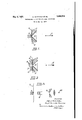
The invention will be described with reference to the accompanying drawings in which Figure 1 shows a modification of our invention as applied to one type of photographic sound recording apparatus;
Figure 2 shows a modification of our invention as applied to the same type of sound recording apparatus; and
Figure 3 shows the first modification of our invention as applied to a different type of sound recording apparatus.
Referring to Fig. 1, a photographic film 1 is run over guide cheeks 2 between which is arranged a prism slit device 3 of the type, for example, described in our U. S. Patent N 0. 1,838,971, issued Dec. 29, 1931.
A reflecting surface 4 is arranged behind the film 1 as shown and the direction of the incident light is indicated by the arrow 5. Light falling upon the film 1 acts upon the sensitive emulsion thereon and the light which penetrates through the film is reflected back by the surface 4 to act once more upon the sensitive emulsion.
In the modified arrangement shown in Fig. 2, the film l is pressed against the guide cheeks 2 by means of a pressure foot 6 having a relawide slot 7 therein. This slot is of sufiicient size to allow substantially all the light reflected by the surface 4 to reach the Great Britain July 3, 1928.
film 1. The reflecting surface 4 is in this case concave and is arranged at such a distance from the film 1 that the light which penetrates the film is reflected back and brought to a focus on the sensitive emulsion.
Fig. 3 shows in Fig. l slit device is used. An is projected by means of the optical system 9 upon the film l, the reflecting surface 4 being arranged as in Fig. 1. A pressure foot may be arranged to press the film into engagement with the reflecting surface 4 but this is not illustrated. The light source is in this figure indicated at 10.
0 means for modulating the intensity of the light beam are illustrated in any of the figures but these may be of any known or suitable type.
In a modification, the film itself is given a backing of opaque and reflecting material and the separate reflecting means may be omitted.
We claim:
1. In apparatus of the class described, the combination of means constituting an effective slit device through which light passes, means for supporting and guiding a moving sensitive film in its movement past said device, and a light-reflecting member in the path of light passing through said device, said film passing between said device and member and said member reflecting back to said film substantially all the light which penetrates the film.
2. In apparatus of the class described, the combination of means constituting an effective slit device through which light passes, means for supporting and guiding a moving sensitive film in its movement past said device, and a mirror in the path of light passing through said device and arranged to reflect light back toward said device, said film passing between said device and mirror.
In apparatus of the class described, the combination of means constitutin an effective slit device through which lig t passes, means for supporting and guiding a moving sensitive film in its movement past said first named means, a member for pressing said and guiding means, and
film into engagement with said supporting means having a surface reflecting back to said film substantially all the light which penetratessaid film.
4. In apparatus of the classdescribed, the
combination of means constituting an effective slit device through which light passes,
, means for supporting and guiding a moving whereby substantially passes, means for sensitive film-in its movement past sal vice, anda mirror in thepath of said light passing through said device, said mirror havsurface arranged to reflect light device and said film,
ing aconcave back toward saldcsllt passing between said device and mirror 5QApparatus of the class describedfcom prisingin combination means constitutmg an effectiv ,Sli fdevice through which light 'L,
supporting and gulding a film'ln ts movement past moving sen sitive said device, means for pressing said film into engagement with said supporting andguidi'ng means, and a light reflecting member in thepath of said lightpassing through said slit device,saidifilmpassing between saidslit device and member and said member reflectinklback to said film substantially all of the lightwhich penetrates the film. I V 6. Apparatus ofi the'f class descr bed comprising m combmation. means constitut ng an efiectiveslitjdevice through which light "passes, means for supporting andguidinga moving sensitive film in its movement past 7 sal'ddevlce,
means for press-ingsaid film into engagement wlth sa d supporting and guldmg means, and a concave mirror positioned in the path of light passing through said slit device and reflecting said light back toward said film, whereby'all of the light "which penetrates said film is' refiected back to said film.
- '7. In combination, means constituting an "effecti e slit devicethrough whichlight may pass, means for supporting and guiding a moving film in its movementpast said device, said film having its, surfaceadjacent said devicesensitive to ligl t, and means on the op posite side of said film for r fl cting light passed through said isensitive surface back onto said surface.
' names to" In testimonywvhereof wehave signed our this specification. v ALFRED lVHITAKER, CECIL OSlVALD BROVVNE.
all of the light which" penetrates the film isreflected to the v
Applications Claiming Priority (1)
| Application Number | Priority Date | Filing Date | Title |
|---|---|---|---|
| GB1856524X | 1928-07-03 |
Publications (1)
| Publication Number | Publication Date |
|---|---|
| US1856524A true US1856524A (en) | 1932-05-03 |
Family
ID=10892110
Family Applications (1)
| Application Number | Title | Priority Date | Filing Date |
|---|---|---|---|
| US364900A Expired - Lifetime US1856524A (en) | 1928-07-03 | 1929-05-21 | Photographic recording of light variations |
Country Status (1)
| Country | Link |
|---|---|
| US (1) | US1856524A (en) |
Cited By (2)
| Publication number | Priority date | Publication date | Assignee | Title |
|---|---|---|---|---|
| US4528654A (en) * | 1979-10-01 | 1985-07-09 | Bogey B.V. | Dustproof case for an optical information tape including a clamping lens |
| US4581729A (en) * | 1979-10-01 | 1986-04-08 | Bogey B.V. | Case containing optically readable carrier structure and apparatus for using same |
-
1929
- 1929-05-21 US US364900A patent/US1856524A/en not_active Expired - Lifetime
Cited By (2)
| Publication number | Priority date | Publication date | Assignee | Title |
|---|---|---|---|---|
| US4528654A (en) * | 1979-10-01 | 1985-07-09 | Bogey B.V. | Dustproof case for an optical information tape including a clamping lens |
| US4581729A (en) * | 1979-10-01 | 1986-04-08 | Bogey B.V. | Case containing optically readable carrier structure and apparatus for using same |
Similar Documents
| Publication | Publication Date | Title |
|---|---|---|
| GB1449246A (en) | Contrast image systems | |
| US1856524A (en) | Photographic recording of light variations | |
| FR2469736A1 (en) | APPARATUS FOR PROJECTING A DISTINCTIVE BRAND IMAGE ON A FILM | |
| US3291555A (en) | Photographic reproduction affaratus | |
| US3544197A (en) | Optical crosscorrelation | |
| GB1510532A (en) | Method and apparatus for detecting data on a photographic recording medium | |
| GB1292646A (en) | Improvements in identity cards incorporating a hologram | |
| US2059083A (en) | Recording of sound with the aid of light | |
| US2073637A (en) | Motion picture system utilizing continuously moving film | |
| US3904835A (en) | Reconstruction method of an optically recorded signal | |
| US2350786A (en) | Sound reproducing unit for sound films | |
| GB424042A (en) | Improvements in making sound records photographically | |
| US1742943A (en) | Automatic control for photographic printing exposures | |
| JP2521325Y2 (en) | Interferometer | |
| US1871643A (en) | Apparatus for sound reproduction with articulate motion picture films | |
| GB315562A (en) | Improvements in or relating to photographic recording of light variations | |
| US2117145A (en) | Film-phonograph for reducing a sound track and rephotographing the reduced track onto a narrow independent film remote from the master film | |
| US2010951A (en) | Apparatus for recording and reproducing sound | |
| US1912157A (en) | Means and method for recording and reproducing photographic sound records | |
| US2006217A (en) | Optical system for photographic sound apparatus | |
| US1822183A (en) | Sound photography system | |
| US1980223A (en) | Light valve for translation of sound effects | |
| US1933251A (en) | Photographic film drive mechanism | |
| US1970102A (en) | Sound recording and reproducing apparatus | |
| SU28044A1 (en) | Device for transversal sound recording on film |