US1856522A - Joint for pile shells - Google Patents
Joint for pile shells Download PDFInfo
- Publication number
- US1856522A US1856522A US395257A US39525729A US1856522A US 1856522 A US1856522 A US 1856522A US 395257 A US395257 A US 395257A US 39525729 A US39525729 A US 39525729A US 1856522 A US1856522 A US 1856522A
- Authority
- US
- United States
- Prior art keywords
- shell
- core
- sections
- section
- concrete
- Prior art date
- Legal status (The legal status is an assumption and is not a legal conclusion. Google has not performed a legal analysis and makes no representation as to the accuracy of the status listed.)
- Expired - Lifetime
Links
- 239000002184 metal Substances 0.000 description 9
- 238000000034 method Methods 0.000 description 2
- 230000003247 decreasing effect Effects 0.000 description 1
- 229920000136 polysorbate Polymers 0.000 description 1
- 230000013707 sensory perception of sound Effects 0.000 description 1
- XLYOFNOQVPJJNP-UHFFFAOYSA-N water Substances O XLYOFNOQVPJJNP-UHFFFAOYSA-N 0.000 description 1
Images
Classifications
-
- E—FIXED CONSTRUCTIONS
- E02—HYDRAULIC ENGINEERING; FOUNDATIONS; SOIL SHIFTING
- E02D—FOUNDATIONS; EXCAVATIONS; EMBANKMENTS; UNDERGROUND OR UNDERWATER STRUCTURES
- E02D5/00—Bulkheads, piles, or other structural elements specially adapted to foundation engineering
- E02D5/22—Piles
- E02D5/52—Piles composed of separable parts, e.g. telescopic tubes ; Piles composed of segments
- E02D5/523—Piles composed of separable parts, e.g. telescopic tubes ; Piles composed of segments composed of segments
-
- E—FIXED CONSTRUCTIONS
- E02—HYDRAULIC ENGINEERING; FOUNDATIONS; SOIL SHIFTING
- E02D—FOUNDATIONS; EXCAVATIONS; EMBANKMENTS; UNDERGROUND OR UNDERWATER STRUCTURES
- E02D7/00—Methods or apparatus for placing sheet pile bulkheads, piles, mouldpipes, or other moulds
- E02D7/28—Placing of hollow pipes or mould pipes by means arranged inside the piles or pipes
- E02D7/30—Placing of hollow pipes or mould pipes by means arranged inside the piles or pipes by driving cores
Definitions
- a drivlng core is enclosed in a shell, the core and shell are driven together and the core is then removed, leaving the hollow shell in the ground to be later filled with concrete to form the pile.
- the core and shell may be of uniform cross-section throughout their length, or they may be tapered.
- the corts and shells may engage each other by means of corrugations on their surfaces, or they may have smooth surfaces and simply rely on their taper to force the shell to follow the core when the core is driven.
- the principal object of the present in: vention is to provide a combination concrete and sheet metal pile section in which a prac tical, cheap, and effective joint is provided between the pile sections so as to exclude dirt and water whilebeing driven on the core and after the core is removed.
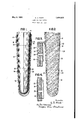
- FIG. 1 is a view of a portion of a pile shell mounted on a core preparatory to driving, the shell being in sections shown in crosssection.
- Fig. 2 is a view of the shell of Fig. 1 after itfhas been driven, the core removed and the shell filled with concrete.
- Fig. 8 is an enlarged view of the joint v "shown in Figs. 1 and 2.
- Fig. '4 is a view of an optional type of joint.
- FIG. 1 10 is a collapsible tapered driving core of familiar type, encased by concrete shell sections 12, 14 and 16.
- the shell and core are prepared for driving by suspending the core in the air and then by means of hoisting tackle drawing the shell sections onto the core one by one beginning at the upper end of the core.
- the shell sections were placed on the core'in the order 12, 14, 16.
- the present invention contemplates so dimensioning the shells that they will always become snug on the core before making end contact, the result being that gaps or spaces of various lengths are left between the sections, for instance, gap 18 between sections 12 and 14 and gap 20 between sections 14 and 16.
- each shell section is provided with a thin metal tube or ferrule 22 surrounding the upper end of the section and extending upwardly.
- the tube is tapered so as to tightly surround the lower end of the next adjacent shell section.
- the gaps be tween the shells decrease by varying amounts.
- the shell sections are forced up to firm hearings on the core, and since the bearings at the bottom of the core are smaller than those at the top, and since the lower sections are subjected to'the most severe service, the gaps between the lower sections are usually decreased more than the gaps higher up.
- the shell is filled with plastic concrete 24 which when hardened forms with the concrete shell a monolithic pile structure.
- plastic concrete 24 which when hardened forms with the concrete shell a monolithic pile structure.
- gap 18 being only partially closed has been filled with concrete 24 whereas gap 20 has closed so completely as to admit no concrete. In either case, intimate contact is made between the shell sections so that the shell portion of the finished pile is effective to carry its share of the load.
- FIGs. 1, 2 and 3 A preferred form of ferrule is shown in Figs. 1, 2 and 3, the designbeing such that each of said concrete sections being provided atone endyonl'y' with afitted ferrule flush with the'outsid e surface of said sect-ionand conforming to the taper thereof, said ferrule en closing andyt ghtly fitting the smooth end of mean adjoining section for the purpose'set' forth.
- a pile-shell comprising a-plu'rality of h-ollow' tapered' concrete section's adapted to enclose a core by which the shell is driven zfii ea'ch of said sections provided at one end only with-a rabbet; and a ferrule ofthin metal seated within saidrabbe't and flush with the surface'of the section-to which the ferrule is attached and conforming-tothe taper there'- -'ofj sai dferruleadapted to enclose the unrabb'eted end of-the next adjacent shell section for thepurposeset forth.
- a tapered pile shell comprising a series of 'hollowiconcrete sections with gaps theresolely maintaining said-gaps and serving to exclude-foreign matter therefrom.
- gap bridging means comprises a sheet metal tube tapered to conform-to the shell sections and engaged with the outside surface of said section's.
- tl1egapi bridging means comprises a tapered-'sheet'metal tube integralwith the sneer one section, tightly surroundinglthe end of the next adjacent section andpreventing contact thereof with the section upon which the-tube is fastened;
- a concrete pile comprising a plurality of hollow concrete shell sections-with gaps therebetwe'en, means for enclosing and main taining said gaps; said means serving'to exelude foreign matter from the gaps," and a' concrete corefilling said sections and'havm-g' -portionsentering said gapsf.-
Landscapes
- Engineering & Computer Science (AREA)
- Structural Engineering (AREA)
- Life Sciences & Earth Sciences (AREA)
- General Life Sciences & Earth Sciences (AREA)
- Mining & Mineral Resources (AREA)
- Paleontology (AREA)
- Civil Engineering (AREA)
- General Engineering & Computer Science (AREA)
- Forms Removed On Construction Sites Or Auxiliary Members Thereof (AREA)
Description
May 3, 1932. E. D. WATT JOINT FOR FILE SHELLS Filed Sept. 26, 1929 FIG.
Av a I B 1 1 1 o u if I D .".0 v. e.
anbemtoz 8. B- Walt" ggfia agg I n 4 p m em Hanna,
Patented May 3, 1932 UNITED STATES PATENT OFFKJE ELIHU '1). Warner LA GRANGE, ILLINOIS, ASSIGNOR 'IO RAYMOND coNoRn'rE PILE COMPANY, OF NEW YORK, N. Y., A CORPORATION OF NEW JERSEY JOINT FOR PILE SHELLS Application filed September 26, 1929. Serial No. 395,257.
In one method of forming and placing concrete piles a drivlng core is enclosed in a shell, the core and shell are driven together and the core is then removed, leaving the hollow shell in the ground to be later filled with concrete to form the pile. The core and shell may be of uniform cross-section throughout their length, or they may be tapered. The corts and shells may engage each other by means of corrugations on their surfaces, or they may have smooth surfaces and simply rely on their taper to force the shell to follow the core when the core is driven.
It has been customary in practice touse thin metal shells, formed in short sections, the sections being placed on the driving core with the upper end of each section overlapping and surrounding the lower end of the section above it, stove-pipe fashion, thus closing the joint between the sections. This procedure is easy with thin flexible metal shells, but is impractical when concrete shells are used, such shells being too thick and rigid to form overlapping joints.
The principal object of the present in: vention is to provide a combination concrete and sheet metal pile section in which a prac tical, cheap, and effective joint is provided between the pile sections so as to exclude dirt and water whilebeing driven on the core and after the core is removed.
Further and other objects of the present invention will become apparent from the specification, claims and appended drawings in which Fig. 1 is a view of a portion of a pile shell mounted on a core preparatory to driving, the shell being in sections shown in crosssection.
Fig. 2 is a view of the shell of Fig. 1 after itfhas been driven, the core removed and the shell filled with concrete.
Fig. 8 is an enlarged view of the joint v "shown in Figs. 1 and 2.
Fig. '4 is a view of an optional type of joint.
Referring to Fig. 1, 10 is a collapsible tapered driving core of familiar type, encased by concrete shell sections 12, 14 and 16.
In practice the shell and core are prepared for driving by suspending the core in the air and then by means of hoisting tackle drawing the shell sections onto the core one by one beginning at the upper end of the core. Thus in Fig. 1, the shell sections were placed on the core'in the order 12, 14, 16.
It is impossible to make the shell sections with such accuracy that the end of each section will become tight on the core at the same time that the upper end of the section contacts with the lower end of the section above it, therefore the present invention contemplates so dimensioning the shells that they will always become snug on the core before making end contact, the result being that gaps or spaces of various lengths are left between the sections, for instance, gap 18 between sections 12 and 14 and gap 20 between sections 14 and 16.
To cover the gaps each shell section is provided with a thin metal tube or ferrule 22 surrounding the upper end of the section and extending upwardly. The tube is tapered so as to tightly surround the lower end of the next adjacent shell section.
During the driving operation the gaps be tween the shells decrease by varying amounts. The shell sections are forced up to firm hearings on the core, and since the bearings at the bottom of the core are smaller than those at the top, and since the lower sections are subjected to'the most severe service, the gaps between the lower sections are usually decreased more than the gaps higher up.
After the shell is driven and the core removed, the shell is filled with plastic concrete 24 which when hardened forms with the concrete shell a monolithic pile structure. It will be noted in Fig. 2 that gap 18 being only partially closed has been filled with concrete 24 whereas gap 20 has closed so completely as to admit no concrete. In either case, intimate contact is made between the shell sections so that the shell portion of the finished pile is effective to carry its share of the load.
A preferred form of ferrule is shown in Figs. 1, 2 and 3, the designbeing such that each of said concrete sections being provided atone endyonl'y' with afitted ferrule flush with the'outsid e surface of said sect-ionand conforming to the taper thereof, said ferrule en closing andyt ghtly fitting the smooth end of mean adjoining section for the purpose'set' forth.
2. A pile-shell comprising a-plu'rality of h-ollow' tapered' concrete section's adapted to enclose a core by which the shell is driven zfii ea'ch of said sections provided at one end only with-a rabbet; and a ferrule ofthin metal seated within saidrabbe't and flush with the surface'of the section-to which the ferrule is attached and conforming-tothe taper there'- -'ofj sai dferruleadapted to enclose the unrabb'eted end of-the next adjacent shell section for thepurposeset forth. I I
13.; A tapered pile shell comprising a series of 'hollowiconcrete sections with gaps theresolely maintaining said-gaps and serving to exclude-foreign matter therefrom. The invention set forth in claim 3 in which'saiclgap bridging means is effective throughout varying changesin size of the gaps during the driving operation.
5. The invention set forth in claim 3 in which said gap bridging means comprises a sheet metal tube tapered to conform-to the shell sections and engaged with the outside surface of said section's. 6. The invention set forth .in claim 8 in which tl1egapi bridging means comprises a tapered-'sheet'metal tube integralwith the sneer one section, tightly surroundinglthe end of the next adjacent section andpreventing contact thereof with the section upon which the-tube is fastened; i
H 7 L A concrete pile comprising a plurality of hollow concrete shell sections-with gaps therebetwe'en, means for enclosing and main taining said gaps; said means serving'to exelude foreign matter from the gaps," and a' concrete corefilling said sections and'havm-g' -portionsentering said gapsf.-
"which sa-id' gap enclosi'ng'means is effective.
throughout varying, changes in 'size'ofthe gaps during the driving operation. v 91- Theinvention-iset forth inclaim 7 between, and meansbridging said gaps and 8L The invention set forth in claim? inwhich said gap enclosing means comprises a sheet metal tube tapered to conform to the shell sections and engaged with the'outside surface of said sections.
10.'The invention set forth in claim 7 in which the gap enclosingmeanscomprises a tapered sheet metal tube. integral with the end of one section, tightly surrounding the,
end of the next adjacent section and prevent which the tube is fast'ened';
In testimony whereof I hereto aflixmy si nature.
Y E LIHU D. WATT.
ing contact thereof withfth'e section "upon-
Priority Applications (1)
| Application Number | Priority Date | Filing Date | Title |
|---|---|---|---|
| US395257A US1856522A (en) | 1929-09-26 | 1929-09-26 | Joint for pile shells |
Applications Claiming Priority (1)
| Application Number | Priority Date | Filing Date | Title |
|---|---|---|---|
| US395257A US1856522A (en) | 1929-09-26 | 1929-09-26 | Joint for pile shells |
Publications (1)
| Publication Number | Publication Date |
|---|---|
| US1856522A true US1856522A (en) | 1932-05-03 |
Family
ID=23562298
Family Applications (1)
| Application Number | Title | Priority Date | Filing Date |
|---|---|---|---|
| US395257A Expired - Lifetime US1856522A (en) | 1929-09-26 | 1929-09-26 | Joint for pile shells |
Country Status (1)
| Country | Link |
|---|---|
| US (1) | US1856522A (en) |
Cited By (1)
| Publication number | Priority date | Publication date | Assignee | Title |
|---|---|---|---|---|
| FR2377485A1 (en) * | 1977-01-13 | 1978-08-11 | Pynford Ltd | PILE AND PILE DRIVING PROCESS DESIGNED FOR THE IMPLEMENTATION OF THIS PROCESS |
-
1929
- 1929-09-26 US US395257A patent/US1856522A/en not_active Expired - Lifetime
Cited By (1)
| Publication number | Priority date | Publication date | Assignee | Title |
|---|---|---|---|---|
| FR2377485A1 (en) * | 1977-01-13 | 1978-08-11 | Pynford Ltd | PILE AND PILE DRIVING PROCESS DESIGNED FOR THE IMPLEMENTATION OF THIS PROCESS |
Similar Documents
| Publication | Publication Date | Title |
|---|---|---|
| US2172052A (en) | Building construction | |
| US5326189A (en) | Method and apparatus for forming a trench with grates or solid covers | |
| US1856522A (en) | Joint for pile shells | |
| US2351288A (en) | Concrete pile | |
| GB1011331A (en) | Improvements in and relating to pre-cast concrete piles | |
| US1463715A (en) | Base for posts, flagstaffs, and the like | |
| CA1258185A (en) | Method of constructing a rigid structure upon the bottom of a water as well as lost casing for performing said method | |
| US3730475A (en) | Form for casting concrete building foundation | |
| US1898380A (en) | Sectional block clay tile | |
| GB2261456A (en) | A shoe for a concrete pile | |
| JPS641610B2 (en) | ||
| US2786255A (en) | Form for pouring concrete ditch dams | |
| US2268044A (en) | Block mold | |
| US3203069A (en) | Apparatus for casting panels from plurality of brick-like bodies | |
| EP0473609A1 (en) | IMPROVEMENTS RELATING TO COMPOSITE POSTS, AND MANUFACTURING METHOD THEREOF. | |
| US2063142A (en) | Pile | |
| ITVI970056A1 (en) | BEAM FOR PREFABRICATED FLOORS AND / OR ARCHITRAVES WITH TRUSS AND BRICK AND BOTTOM FOR THIS BEAM. | |
| US1584019A (en) | Concrete wall construction | |
| US3137140A (en) | Pile structure | |
| US2322819A (en) | Sheet piling | |
| US871778A (en) | Cement-pipe mold. | |
| US1787971A (en) | Means of making joints in sewer or drain pipes | |
| US2047344A (en) | Method of forming foundation piles | |
| US1926962A (en) | Pile and pile driving | |
| US1369296A (en) | Concrete building |