US1856511A - Adjustable dough dispensing machine - Google Patents
Adjustable dough dispensing machine Download PDFInfo
- Publication number
- US1856511A US1856511A US544525A US54452531A US1856511A US 1856511 A US1856511 A US 1856511A US 544525 A US544525 A US 544525A US 54452531 A US54452531 A US 54452531A US 1856511 A US1856511 A US 1856511A
- Authority
- US
- United States
- Prior art keywords
- dough
- arm
- members
- dispensing machine
- arms
- Prior art date
- Legal status (The legal status is an assumption and is not a legal conclusion. Google has not performed a legal analysis and makes no representation as to the accuracy of the status listed.)
- Expired - Lifetime
Links
Images

Classifications
-
- A—HUMAN NECESSITIES
- A21—BAKING; EDIBLE DOUGHS
- A21C—MACHINES OR EQUIPMENT FOR MAKING OR PROCESSING DOUGHS; HANDLING BAKED ARTICLES MADE FROM DOUGH
- A21C11/00—Other machines for forming the dough into its final shape before cooking or baking
- A21C11/16—Extruding machines
- A21C11/163—Applying co-extrusion, i.e. extruding two or more plastic substances simultaneously, e.g. for making filled dough products; Making products from two or more different substances supplied to the extruder
Definitions
- One object of my invention is to provide an adjustable dough dispensing machine of simple, durable and inexpensive construction.
- a further object of my present invention is to provide an improved type of adjustment for dough dispensing machines which may be easilyadjusted while the machine is in voperation and which is an improvement over the adjustment shown in my copending application Serial Number 444,290, filed April 4, 1930, which issued into Patent No'. 1,811,564 on June 23, 1931.
- a dough dispensing machine having a dough hopper and a pair of movable members for dispensing dough from the hopper, an arm operatively connected with each movable member, a drive shaft, means thereon coacting with the arms for moving them upon rotation of the shaft and individual bearing members for each arm, the arms being pivoted thereto and the bearing members being capable of movement transversely of the arms to vary the strokes of the movable members 25 without affecting the leverage of the arms,
- Still a further object is to provide a readily operable means'for adjusting the bearing members to which the arms are pivoted and to provide for their simultaneous adjustment if such construction is desirable.
- Still another object is to provide means for locking the bearing members in any desired position to which they are adjusted.
- Still another object is to provide a cylindrical guide with guide extensions for the movable members so that when certain adjustment-s are made, thefparts do not become longitudinally disassociated.
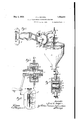
- Figurey 1 is a perspective view of a dough dispensing machine embodying my present invention.
- Figure 2 is an enlarged, vertical sectional view on the line 2 2 of Figure 1 showing the coaction of cams with arms which operate to dispense dough from the machine.
- Figure 3 is a vertical view on the line 3 3 of Figure 1 showing the adjustable parts in detail.
- Figure 4 is a vertical sectional View longitudinally of the dough dispensing machine as on the line 4 4 of Figure 2, showing a cam, its coaction with one of the arms andthe movable members for dispensing dough from the dough hopper.
- Figure 5 is a sectional view on the line 5 5 of Figure 4 showing a guide construction for the movable members.
- Figure 6 is a diagrammatic view showing the operation of the dough dispensing machine and adjusted to one position.
- Figure 7 is a similar diagrammatic view showing the parts adjusted to another position.
- Figure 8 is a sectional view similar to the left handend of Figure 4 showing a modified construction.
- bracket 1 may be secured to a wall surface or the like.
- Pivotally mounted supporting arms 12 extend from the bracket 10 and support a cam housing 14.
- a drive shaft 16 is j ournalled in the housing 14 and may be rotated by a hand crank 18 or an electric motor as shown in my copending application hereinbefore referred to.
- the drive shaft 16 has a pair of cams 2O and 22 secured thereto as best shown in Figure 2 of the drawings.
- a hopper supporting ring 24 is secured to the housing 14 and supports a dough hopper 26.
- the hopper 26 has a discharge neck 28 in which is removably mounted a cylindrical guide 30.
- the cylindrical guide 30 may be secured in position within the discharge neck 28.
- Movable members or pistons 36 and 38 re- 'ciprocate through the cylindrical guide-30 and at times during certain adjustments oit the "machine the piston 36 is withdrawn upwardly yfrom the cylindrical guide 30..
- VGruide extensions 40 are therefore provided, extending yupwardly from the cylindrical guide and located within the'hopper 26. VThese guide the piston 36 when it is above the upper end of the cylindrical guide 30.
- Different sized cylindrical guides 30 or dies, as they are ordinarily called,y may be substituted in place of the one shown and the pistons 36 and 38 replaced by" others of suitable size for the purpose of regulating the sizes of the charges of dough dispensed (which areY dispensed in the form of doughnuts);
- a piston rod 42 is connected with'the piston 38 andis sl'idabl'e through a bearingV 44 in nuts? are tightened.
- the arm 46 extends from' the/housing 14.
- a pair' of piston' rods 48 extend upwardly from ⁇ the ,piston 36.
- the pistonVY rods 48 are connected'with a block 50 while thepiston rod 42 isconnected with a' blockz5-2f.' ⁇ 'Ihe ⁇ piston rod 42 slidablyl extends through uit piston 36.
- The' blocks 5o' and 52 i have laterally extending pins 54 and 56 respectively with which forked ends of arms 58 and 60 coact.
- the arms 58 and 60 are pivoted on pini-'i162 and 64 respectively.
- the arm'shave' rollers 66 and 68 journalled on stud' pins 66a'and 68a.
- Therollefrs 66 and 68 coact with the cam grooves of the cams 22 as best shown in' Figure 2.'. i
- the pivot pins 62 and '64 are; supported in U-shapedbrackets or bearings 7() and 72 respectively which snugly lit within the casing 14'a ⁇ s best shown in Figure 3 of the drawings.
- These bearings are Imovable transversely with respect to the'a'rm's 58' and 60 and thepivot pins 62 'and 64Y have threaded extensions 7 4 and 7 6 for locking them in adjusted positions.
- extensions 'Z4 and 76 extend thror'igh' slots 78'in ⁇ t'he housing 14 and are provided with winglnuts 8Qiforwretaining the bearings 70" 2 in any desired position when thev wing VQFor adjusting the positions of the bearings 70: and 72' I provide screw threaded extensions 82 with which adj ustingrn'uts 84screw threadedly coac't. 'Ihev adjusting nuts 84' are held against longitudinal movement relative/to the housmg 14 by shoulders 86.
- a controlrod 94 is j ournalled at 96 and 98 in the-housing 14: Longitudinal movlementl thereof is prevented by a collar 100' and an adj ustingnut 102, The c ontrolrodf 94 has rightand left handthreadscoac-ting with the bearing members7Oa/ Pand' 220;, whereby they are simultaneously adj-usted ill-Opposite difrections. l This eliminates one adjustment control although it providesan adjustment without the flexibility of the one shownin Figure 4 wherein the arms 58 and 60 are individually adjustable as desired.-
- a dough hopper a pair of reciprorable members for dispensing charges of dough from said hopper, an arm operatively connected with each reciprocable member, a. shaft, means thereon coacting with each arm to move them upon rotation of the shaft, bearing members, one end of each arm being pivoted thereto, said bearing members being capable of movement in directions substantially parallel with the direction of the movement ofthe reciprocable members to vary the strokes of said reciprocable members substantially Without varying the distances between the pivot points, the cams and the reciprocable members.
- a dough hopper a pair of reciprocable members for dispensing charges of dough therefrom, an arm operatively connected with each reciprocable member, a shaft, means thereon for coacting with each arm to move them upon rotation of said shaft, a bearing member, one end of one of said arms being pivoted thereto, said bearing member being capable of movement in a direction substantially parallel with the direction of movement of said reciprocable member to vary the stroke of said' arm relative to said means substantially without varying the distances between the pivot point, the means and said reciprocable member.
- a dough dispensing machine having a dough hopper and a movable member for dispensing dough therefrom, a shaft, an arm having one end pivotally connected with said movable member, means on said shaft and coacting with said arm to move the same upon rotation of the shaft, a bearing member,
- said bearing member being movable transversely relative to said arm to vary the pivot point of said arm relative to said means and thereby vary the movement of said movable member substantially without varying the distances between the pivot point, the means and said reciprocable member.
- a dough hopper for dispensing charges of dough therefrom, an arm having one end' operatively connected with each movable member, a shaft, means thereon for coacting with each arm to move them upon rotation of said shaft, bearing members, the other end of each arm being pivoted thereto, said bearing members being capable of movement transversely of said arms to vary the strokes of said movable members substantially without changing the distances between the means, the bearing members and the movable members.
- a dough dispensing machine comprising a dough hopper, a pair of movable members for dispensing charges of dough from said hopper, an arm operatively connected with each movable member, a shaft, means thereon for coacting with each arm to move them upon rotation of the shaft, a bearing member, one end of one of said arms being pivoted thereto, said bearing member being capable of movement transversely of said arm to vary the stroke of the movable member connected therewith substantially without changing the distances between said bearing member, said means and said movable member.
- a dough dispensing machine a dough hopper, a pair of movable members for dispensing charges of dough therefrom, an arm having one end operatively connected with each movable member, a shaft, means thereon coacting with each arm to move the arms upon rotation of the shaft, bearing members, the other end of each arm being pivoted thereto, said bearing members being capable of simultaneous movement transversely of said arms and in opposite directions to vary the strokes of said movable members substantially without changing the distances between said bearings, said means and said movable members.
Landscapes
- Life Sciences & Earth Sciences (AREA)
- Engineering & Computer Science (AREA)
- Food Science & Technology (AREA)
- Manufacturing And Processing Devices For Dough (AREA)
Description
May 3, 1932. F. scHoEl.
ADJUSTABLE DOUGH DISPENSING MACHINE Filed June l5', 1931 2 Sheeis-Sheet F. L. SCHOEL ADJUSTABLE DOUGH DISPENSING MACHINE Filed June 15, 1931 2 Sheets-Sheet 2 May 3, 1932.
Patented May 3, 1932 UNITED STATES PATENT OFFICE FRED L. SCHOEL, F WATERLOO, IOWA, ASSIGNOR TO GEM DOUGBNUT MACHINE CO., i INC., 0F WATERLOO, IOWA, A CORPORATION ADJUSTABLE DOUGH DISPENSING MACHINE Application led J' une 15,
One object of my invention is to provide an adjustable dough dispensing machine of simple, durable and inexpensive construction.
' A further object of my present invention is to provide an improved type of adjustment for dough dispensing machines which may be easilyadjusted while the machine is in voperation and which is an improvement over the adjustment shown in my copending application Serial Number 444,290, filed April 4, 1930, which issued into Patent No'. 1,811,564 on June 23, 1931.
More particularly it is my object to provide in a dough dispensing machine having a dough hopper and a pair of movable members for dispensing dough from the hopper, an arm operatively connected with each movable member, a drive shaft, means thereon coacting with the arms for moving them upon rotation of the shaft and individual bearing members for each arm, the arms being pivoted thereto and the bearing members being capable of movement transversely of the arms to vary the strokes of the movable members 25 without affecting the leverage of the arms,
such variation in the strokes of the movable members being provided for the purpose ofchanging the sizes of the charges of dough dispensed from the hopper. 30 Still a further object is to provide a readily operable means'for adjusting the bearing members to which the arms are pivoted and to provide for their simultaneous adjustment if such construction is desirable.
Still another object is to provide means for locking the bearing members in any desired position to which they are adjusted.
Still another object is to provide a cylindrical guide with guide extensions for the movable members so that when certain adjustment-s are made, thefparts do not become longitudinally disassociated.
With these and other objects in view my invention consists in the construction, arrangement and combination of the various parts of my device, whereby the objects contemplated areattained, as hereinafter more fully set forth, pointed out in my claims and illustrated in the accompanying drawings, in which:
1931. Serial No. 544,525.
Figure 2 is an enlarged, vertical sectional view on the line 2 2 of Figure 1 showing the coaction of cams with arms which operate to dispense dough from the machine.
Figure 3 is a vertical view on the line 3 3 of Figure 1 showing the adjustable parts in detail.
Figure 4 is a vertical sectional View longitudinally of the dough dispensing machine as on the line 4 4 of Figure 2, showing a cam, its coaction with one of the arms andthe movable members for dispensing dough from the dough hopper.
Figure 5 is a sectional view on the line 5 5 of Figure 4 showing a guide construction for the movable members.
Figure 6 is a diagrammatic view showing the operation of the dough dispensing machine and adjusted to one position.
Figure 7 is a similar diagrammatic view showing the parts adjusted to another position; and
Figure 8 is a sectional view similar to the left handend of Figure 4 showing a modified construction.
On the accompanying drawings, I have used the reference numeral l0 to indicate a supporting bracket. The bracket 1() may be secured to a wall surface or the like. Pivotally mounted supporting arms 12 extend from the bracket 10 and support a cam housing 14.
A drive shaft 16 is j ournalled in the housing 14 and may be rotated by a hand crank 18 or an electric motor as shown in my copending application hereinbefore referred to. The drive shaft 16 has a pair of cams 2O and 22 secured thereto as best shown in Figure 2 of the drawings.
A hopper supporting ring 24 is secured to the housing 14 and supports a dough hopper 26. The hopper 26 has a discharge neck 28 in which is removably mounted a cylindrical guide 30. By means of a peripheral groove 32 andy aset screw 34 the cylindrical guide 30 may be secured in position within the discharge neck 28.
Movable members or pistons 36 and 38 re- 'ciprocate through the cylindrical guide-30 and at times during certain adjustments oit the "machine the piston 36 is withdrawn upwardly yfrom the cylindrical guide 30.. VGruide extensions 40 are therefore provided, extending yupwardly from the cylindrical guide and located within the'hopper 26. VThese guide the piston 36 when it is above the upper end of the cylindrical guide 30.
Different sized cylindrical guides 30 or dies, as they are ordinarily called,y may be substituted in place of the one shown and the pistons 36 and 38 replaced by" others of suitable size for the purpose of regulating the sizes of the charges of dough dispensed (which areY dispensed in the form of doughnuts);
. A piston rod 42 is connected with'the piston 38 andis sl'idabl'e through a bearingV 44 in nuts? are tightened.
a supporting arm A46. The arm 46 extends from' the/housing 14. A pair' of piston' rods 48 extend upwardly from` the ,piston 36. The pistonVY rods 48 are connected'with a block 50 while thepiston rod 42 isconnected with a' blockz5-2f.'` 'Ihe` piston rod 42 slidablyl extends through uit piston 36. The' blocks 5o' and 52 i have laterally extending pins 54 and 56 respectively with which forked ends of arms 58 and 60 coact. yThe arms 58 and 60are pivoted on pini-'i162 and 64 respectively. The arm'shave' rollers 66 and 68 journalled on stud' pins 66a'and 68a. Therollefrs 66 and 68 coact with the cam grooves of the cams 22 as best shown in' Figure 2.'. i
The pivot pins 62 and '64 are; supported in U-shapedbrackets or bearings 7() and 72 respectively which snugly lit within the casing 14'a`s best shown in Figure 3 of the drawings. These bearings are Imovable transversely with respect to the'a'rm's 58' and 60 and thepivot pins 62 'and 64Y have threaded extensions 7 4 and 7 6 for locking them in adjusted positions. extensions 'Z4 and 76 extend thror'igh' slots 78'in`t'he housing 14 and are provided with winglnuts 8Qiforwretaining the bearings 70" 2 in any desired position when thev wing VQFor adjusting the positions of the bearings 70: and 72' I provide screw threaded extensions 82 with which adj ustingrn'uts 84screw threadedly coac't. 'Ihev adjusting nuts 84' are held against longitudinal movement relative/to the housmg 14 by shoulders 86.
In Figure 6 I-have shown theY upper and lower pistons 36 and'38 lin their various'positions during a cycle of operation of the ma- They then both move downwardly downwardly so that Ythetpiston 36 is ai higher relative position as shown in Figure 7.
In Figure 7 the various views are indicated at A, B', G and-D, the same as in Figure 6.( It will be noted that the distance between the pistons 36 and 38 in all of their positions is greater than in igure 6. This Acauses the dispensing of the doughnut 92Y Off approximately the same internal diameter, but of greater volume. The internal diameter can be changed by changing. thedie 3Q and the pistons v36y andf 38. l Y Y Y I have foundvthe disclosed typeof adjustment particularly desirable because it does not change the etl'ective leverage of the arms 58 and kt but only` changes the position of the stroke of the piston The lengthof the stroke is between certain limits at Aoney adjustment, and is of the same lengthsbut between higher or lower limits at other adjustments'. Y
In Figure 7 I havehshown adifferen'ce of adjustment over Figure6 ofthe upperpiston only but itis obvious lthat the lower, one can also beY adjustedv whereby thevolume kof ythe doughnut 92 may be made stillgreater.y
1111 Figure 8; IhaveshQWn-,bearnig members M172@ Cerresponding tothe bearings 70 @C172 as being Off a little dfferentfformaton and having SGreW threaded, openings therethrough.- A controlrod 94 is j ournalled at 96 and 98 in the-housing 14: Longitudinal movlementl thereof is prevented by a collar 100' and an adj ustingnut 102, The c ontrolrodf 94 has rightand left handthreadscoac-ting with the bearing members7Oa/ Pand' 220;, whereby they are simultaneously adj-usted ill-Opposite difrections. l This eliminates one adjustment control although it providesan adjustment without the flexibility of the one shownin Figure 4 wherein the arms 58 and 60 are individually adjustable as desired.-
Some changes may be made inthe construction and arrangement of theparts of lny'd'e: vice without departing from ithe realspirit and purpose' of myy invention,- and'it` is my irrtentior'iV to cover by my claimsanyl Inodied forms of structure or use ofi mechanical equivwithintheir scope'.v l
I claimy asmy"invention?V i 1. In a] dough` dispensing-mac'hi-'ne having adou-ghvhop-per andl a reci-procabfle member for ldispensing dough therefrom', a shaft', Camfh'efeonrlm PVBHY CIQC-l With sain reciprocable member' and arranges at valents which may be reasonablyfinciluded substantially right angles thereto, the cam surface of said cam coacting with said arm intermediate the ends thereof to move the same upon rotation of the shaft, a bearing member, one end of said arm being pivoted thereto, said bearing member being movable in a direction substantially parallel with the direction of movement of the reciprocable member to vary the pivot point of said arm relative to said cam and to thereby vary the stroke of said reciprocable member substantially without varying the distances between the pivot point, the cam and the reciprocable member.
2. In a dough dispensing machine, a dough hopper, a pair of reciprorable members for dispensing charges of dough from said hopper, an arm operatively connected with each reciprocable member, a. shaft, means thereon coacting with each arm to move them upon rotation of the shaft, bearing members, one end of each arm being pivoted thereto, said bearing members being capable of movement in directions substantially parallel with the direction of the movement ofthe reciprocable members to vary the strokes of said reciprocable members substantially Without varying the distances between the pivot points, the cams and the reciprocable members.
3. In a dough dispensing machine, a dough hopper, a pair of reciprocable members for dispensing charges of dough therefrom, an arm operatively connected with each reciprocable member, a shaft, means thereon for coacting with each arm to move them upon rotation of said shaft, a bearing member, one end of one of said arms being pivoted thereto, said bearing member being capable of movement in a direction substantially parallel with the direction of movement of said reciprocable member to vary the stroke of said' arm relative to said means substantially without varying the distances between the pivot point, the means and said reciprocable member.
4. In a dough dispensing machine having a dough hopper and a movable member for dispensing dough therefrom, a shaft, an arm having one end pivotally connected with said movable member, means on said shaft and coacting with said arm to move the same upon rotation of the shaft, a bearing member,
the other end of said' arm being pivoted thereto, said bearing member being movable transversely relative to said arm to vary the pivot point of said arm relative to said means and thereby vary the movement of said movable member substantially without varying the distances between the pivot point, the means and said reciprocable member.
5. In a dough dispensing machine, a dough hopper, a pair of movable members for dispensing charges of dough therefrom, an arm having one end' operatively connected with each movable member, a shaft, means thereon for coacting with each arm to move them upon rotation of said shaft, bearing members, the other end of each arm being pivoted thereto, said bearing members being capable of movement transversely of said arms to vary the strokes of said movable members substantially without changing the distances between the means, the bearing members and the movable members.
6. A dough dispensing machine, comprising a dough hopper, a pair of movable members for dispensing charges of dough from said hopper, an arm operatively connected with each movable member, a shaft, means thereon for coacting with each arm to move them upon rotation of the shaft, a bearing member, one end of one of said arms being pivoted thereto, said bearing member being capable of movement transversely of said arm to vary the stroke of the movable member connected therewith substantially without changing the distances between said bearing member, said means and said movable member.
7. In a dough dispensing machine, a dough hopper, a pair of movable members for dispensing charges of dough therefrom, an arm having one end operatively connected with each movable member, a shaft, means thereon coacting with each arm to move the arms upon rotation of the shaft, bearing members, the other end of each arm being pivoted thereto, said bearing members being capable of simultaneous movement transversely of said arms and in opposite directions to vary the strokes of said movable members substantially without changing the distances between said bearings, said means and said movable members.
Des Moines, Iowa, May 29th, 1931.
FRED L. SCI-IGEL.
Priority Applications (1)
| Application Number | Priority Date | Filing Date | Title |
|---|---|---|---|
| US544525A US1856511A (en) | 1931-06-15 | 1931-06-15 | Adjustable dough dispensing machine |
Applications Claiming Priority (1)
| Application Number | Priority Date | Filing Date | Title |
|---|---|---|---|
| US544525A US1856511A (en) | 1931-06-15 | 1931-06-15 | Adjustable dough dispensing machine |
Publications (1)
| Publication Number | Publication Date |
|---|---|
| US1856511A true US1856511A (en) | 1932-05-03 |
Family
ID=24172528
Family Applications (1)
| Application Number | Title | Priority Date | Filing Date |
|---|---|---|---|
| US544525A Expired - Lifetime US1856511A (en) | 1931-06-15 | 1931-06-15 | Adjustable dough dispensing machine |
Country Status (1)
| Country | Link |
|---|---|
| US (1) | US1856511A (en) |
Cited By (4)
| Publication number | Priority date | Publication date | Assignee | Title |
|---|---|---|---|---|
| US2643621A (en) * | 1947-01-18 | 1953-06-30 | Thomas E Belshaw | Dough former |
| US2742198A (en) * | 1953-09-18 | 1956-04-17 | Thomas E Belshaw | Dough dispensing machine |
| US2770163A (en) * | 1950-12-19 | 1956-11-13 | Bell Telephone Labor Inc | Non-intermittent projector for motion pictures |
| US3003439A (en) * | 1959-09-08 | 1961-10-10 | Thomas E Belshaw | Dough forming machine |
-
1931
- 1931-06-15 US US544525A patent/US1856511A/en not_active Expired - Lifetime
Cited By (4)
| Publication number | Priority date | Publication date | Assignee | Title |
|---|---|---|---|---|
| US2643621A (en) * | 1947-01-18 | 1953-06-30 | Thomas E Belshaw | Dough former |
| US2770163A (en) * | 1950-12-19 | 1956-11-13 | Bell Telephone Labor Inc | Non-intermittent projector for motion pictures |
| US2742198A (en) * | 1953-09-18 | 1956-04-17 | Thomas E Belshaw | Dough dispensing machine |
| US3003439A (en) * | 1959-09-08 | 1961-10-10 | Thomas E Belshaw | Dough forming machine |
Similar Documents
| Publication | Publication Date | Title |
|---|---|---|
| US1856511A (en) | Adjustable dough dispensing machine | |
| GB1441633A (en) | Device for varying the vertical separation and the relative longi tudinal inclination of the sitting surfaces of seats | |
| US1866061A (en) | Doughnut forming machine | |
| US2011980A (en) | Tandem cylinder glass plunger actuator | |
| US2228245A (en) | Work feeding apparatus | |
| US4212416A (en) | Fine tune adjusting mechanism for tandem-operated filling units of a filling machine | |
| US1926764A (en) | Glass feeding apparatus | |
| US2351315A (en) | Ink fountain | |
| US1477857A (en) | Depositing machine | |
| US1867307A (en) | Doughnut machine and the like | |
| US1793486A (en) | Lapping machine | |
| US1811564A (en) | Adjustable doughnut machine | |
| US2105237A (en) | Metal cutting machine | |
| US1095126A (en) | Sheet-gage for printing-presses. | |
| US2276465A (en) | Registering mechanism for printing machines | |
| US1870654A (en) | Dough dispensing device | |
| US2291591A (en) | Threader for collapsible tube trimming machines | |
| US809521A (en) | Ink-distributer for printing-presses. | |
| US1505991A (en) | Automatic wire straightening and cutting-off machine | |
| US2158708A (en) | Adjustable shears | |
| US2325389A (en) | Hold-down control for slab squeezers | |
| US977170A (en) | Printing-press inking device. | |
| US2685765A (en) | Glass feeder plunger-operating mechanism | |
| US124460A (en) | Improvement in printing-presses | |
| US1839241A (en) | Line casting machine |