US1856500A - Air conditioning apparatus - Google Patents
Air conditioning apparatus Download PDFInfo
- Publication number
- US1856500A US1856500A US112374A US11237426A US1856500A US 1856500 A US1856500 A US 1856500A US 112374 A US112374 A US 112374A US 11237426 A US11237426 A US 11237426A US 1856500 A US1856500 A US 1856500A
- Authority
- US
- United States
- Prior art keywords
- valve
- core
- fan
- casing
- shaft
- Prior art date
- Legal status (The legal status is an assumption and is not a legal conclusion. Google has not performed a legal analysis and makes no representation as to the accuracy of the status listed.)
- Expired - Lifetime
Links
- 238000004378 air conditioning Methods 0.000 title description 7
- 239000012530 fluid Substances 0.000 description 21
- 238000010438 heat treatment Methods 0.000 description 14
- XLYOFNOQVPJJNP-UHFFFAOYSA-N water Substances O XLYOFNOQVPJJNP-UHFFFAOYSA-N 0.000 description 7
- 210000002445 nipple Anatomy 0.000 description 6
- 238000010276 construction Methods 0.000 description 5
- 241001527902 Aratus Species 0.000 description 1
- 230000006835 compression Effects 0.000 description 1
- 238000007906 compression Methods 0.000 description 1
- 238000004519 manufacturing process Methods 0.000 description 1
- 239000002184 metal Substances 0.000 description 1
- 230000004048 modification Effects 0.000 description 1
- 238000012986 modification Methods 0.000 description 1
- 230000000717 retained effect Effects 0.000 description 1
- 238000005507 spraying Methods 0.000 description 1
Images
Classifications
-
- F—MECHANICAL ENGINEERING; LIGHTING; HEATING; WEAPONS; BLASTING
- F24—HEATING; RANGES; VENTILATING
- F24F—AIR-CONDITIONING; AIR-HUMIDIFICATION; VENTILATION; USE OF AIR CURRENTS FOR SCREENING
- F24F11/00—Control or safety arrangements
- F24F11/30—Control or safety arrangements for purposes related to the operation of the system, e.g. for safety or monitoring
Definitions
- a heating unit adapted to be adjust-ably suswater is delivered to the air when the apparatus is in operation.
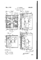
- FIG. 1 is a rear elevation of an air conditioning device embodying the invention
- Figure 3 is a section taken on line 3-3 of ' Figure 2;
- FIG. 4 is a central section taken through an air conditioning device embodying another form of the invention.
- the reference character 10 designates'generally an air conditioning device embodying the invention and preferably comprising a housing 11 which in this instance 1s formed from upper and lower manifold members 12 and 13, respectively, and side plates 14. Secured to the manifold members 12 and 13 is a radiator core 16 preferably comprising upper and lower tanks 17 and 18, respectively. . The radiator core 16 is preferabl secured to the manifold members12 and 59 13 y bolts 19 or the equivalent which extend 1926. Serial No. 112,374.
- tanks 17 and 18 Formed in the manifold members 12 and 13 are passages 22 and 23, respectively, which communicate with the tanks 17 and 18, respectively.
- the tanks 17 and 18A communicate with each other through ,tubes 25 which are preferably formed from relatively thin sheet metal, the
- nipple 27 which communicates with the passage 22, and arranged coaXia-lly with the nipple 27 and projecting into the manifold 13 1s a nipple 28.l
- the nipple 27 is preferably connected-to a steam or hot Water pipe (not shown) by means comprising a pipe union 30 and the nipple 28 is preferably connected to a drain or return pipe (not shown) by means comprising a pipe union 32.
- a bracket 35 which supports an electric motor 36 adapted to drive a fan 37, the motor being conof electrical energy.
- the motor 36 a column of heated air wil .be advanced from the device.
- valved fitting 39 provided with ya lever 40 whereby the valve may be opened or closed.
- T fitting 42 Extending from the valved fitting 39 is a T fitting 42 provided with a plurality of perforations 44. This construction permits steam or hot water to flow from the passage 22 through the perforations 44 when the valve is in its open position.
- the valve is preferably controlled by means comprising a link 45 which connects the ⁇ free end of the lever 40 with one end of a lever 46, ⁇ the lever 46'being pivotally mounted intermediate" a bearing member 48 engageable with one end of the motor shaft.
- Aspring 49 secured to the lever 46 and to the bracket 47 urges the lever 46 in a clockwise direction (see 5 Figure 2) and tends to keep theI aforementioned valve in its closed position so that.
- sufiicient play is generally7 provided in electric motors so that the shafts ma)1 shift longitudinally therein.
- the motor shaft is urged to the left ( Figure 2) by the spring 49 ut when the fan is in operation the resistance of the air causes the fan and shaft to assume'the positions wherein they are shown in full linesin Figure 2. That movement isagainstA the action of the spring 49.
- the operation of the above described ap- ⁇ aratus is substantially as follows: Assumlng that the motor 37 is not in operation, the fan 37 and themotor shaft will be retained in the positions wherein they are shown in full lines in Figure 2 so that the valved fitting 39 does not permit the Huid to pass from the passage 22 through the apertures 44. If the motor 36 is then set in operation, the fan and motor shaft move into the positions wherein they are shown in dotted lines in Figure 2 and the valved fitting is opened. The fan then advances a column of air ⁇ through the radiator core 16, the air being heated by steam or hot water flowing through the core. Simultaneously, moisture is supplied to theair by way ofthe passage 22, the
- valved fitting 39 and thel apertures 44 in the T fitting 42 are
- the reference character designates generally an .air conditioning device which preferably comprises upper and lower manifolds 61 and 62, respectively, and a radiator core 63.
- T he manifolds 61 and 62 and the radiator core 63 are preferably identical with the aforementioned manifolds 12 and 13 and the .radiator core 16, respectively.
- a bracket 65 mounted upon the manifold 62 is adapted to support an electric motor66 having a shaft 67 carrying afan 68a, the fan being adapted to advance a. column of air through the radiator core 63.
- the device 60 may be supported from a steam or hot water pipe in substantially the same manner as the aforementioned device 10, the steam or hot water being circulated through the radiator core 63 by way of passages 68 formed in the manifolds 61 and' "i 62. Screw-threaded into the 4manifold 61 @go and communicating with the passage 68 -" ⁇ therein is a valved fitting 70, vthe valve of which is operated by a reciproca-tory valve stem 72.
- a compression. spring 74 wound around the valve stem 7 2l normally holds the v ,valvehn a position wherein fluid may pass through the fitting and engageable with the valve stem 72 is a lever 76 which is pivoted intermediate its ends upon a bracket 78 carried by the radiator core 63.
- One end of the lever 76 is engageable with the motor shaft 67 which is normally urged to the left ( Figure 4) by a leaf spring ⁇ 79 fixed to the bracket 65.
- the construction is such that when the fan 68a is not in motion, the shaft 67 holds the lever 76 in a position where it depresses the valve stem 72 against the action of the spring 74 and the passage through the valve fitting 7 0 is closed.
- the motor 66 is set in operation the fan 68a and the shaft 67 move into the positions wherein the are shown in dotted lines in Figure 4 an the spring 74 functions to open the valve in the fitting. Fluid may then pass from the passage 68 in the manifold 60 through the fitting 70.
- T fitting 7 5 Screw-threaded into the fitting is a T fitting 7 5 provided with perforations 76a which distribute an fluid which may pass through the fitting 0.
- the T fitting 75 is preferably identical with the aforementioned T fitting 42.
- a radiator provided with passages for a heating fluid, means including a valve connected to one of said passages for delivering a part of said fluid to the atmosphere, a fan including fan blades and a motor for advancing a. column of air through said radiator, a shaft for said motor, said fan blades connected to said motor4 shaft, means for operating said valve, said valve operating means engaging said motor'shaft, said motor shaft being capable of longitudinal movement, means urging said shaft in the direction of theadvancing column of air to close said valve, said shaft being moved in the opposite direction and opening said valve when the fan is in motion.
- a radiator core having passages for conducting an aqueous heating fluid
- a! pair of aligned conduits for conducting such fluid to and from said radiator core, said conduits serving as pivots upon which said casing may be rotated
- means for delivering a portion of said heating fluid into the atmosphere adjacent said core means for delivering a portion of said heating fluid into the atmosphere adjacent said core, a fan mounted within said casing for projecting a current of moistened air through said core, and valve means associated with said delivering means and controllable by said fan.
- a radiator core having passages for conducting an aqueous heating fluid, a pair of aligned conduits for conducting such liuid to and from said radiator core, said conduits serving as pivots upon which said casing may be rotated, means'for delivering a portion of said heating fluid into the atmosphere adjacent said core, a fan mounted Within said casing for projecting a current of moistened air through said core, valve means for controlling the 'delivery of fluid from said delivery means, and a lever operable by the axial movement of the shaft of said fan for controlling said valve.
- a radiator core having passages for conducting an aqueous heating fluid, a pair of aligned conduits for conducting such iuid to and from said radiator core, said conduits serving as pivots upon which said casing may be rotated, means for delivering a portion of said heating fluid into the atmosphere adjacent said core, a fan mounted Within said casing for projecting a current of' moistened air through said core, valve means for controlling the delivery of fluid from said delivery means. resilient means for normally retaining said valve in closed position, and a lever operable by the axial movement of the shaft of said fan when in operation for opening said valve.
- a radiator core having passages for an aqueous heating liuid, a pair of aligned conduits for conducting such fluid to and from said radiator core, said conduits servingas pivots upon "which said 4casing may be rotated, tubular means having having passages for an aqueous heating fluid,
- a radiator core having passages for an aqueous heatin iiuid, a pair of aligned conduits for Icon ucting such fluid to and from said radiator core, said conduits serving as pivots upon which said casing may be rotated, tubular means having spaced apertures therein disposed inthe upper portlon of said casing for delivering a portion of said heating fluid into the atmosphere adjacent said core, a fan mounted Within said casing for projecting a current of moistened air through said core, valve means for controlling the delivery of Huid from said delivery means, resilient means for normally retaining said valve in closed position, and a lever operable by the axial movement of the shaft of said fan when in operation for opening said valve.
- a radiator core means carrying said core and connected with the core for circulating a heating medium through said core, means for advancing a column of air through said core, and means communicating with said first mentioned means for delivering moisture to the column of air, said means including means extending along an edge of said core and providing means for spraying and delivering said moisture to said column Y ARTHUR B. MoDiNE.
Landscapes
- Engineering & Computer Science (AREA)
- Chemical & Material Sciences (AREA)
- Combustion & Propulsion (AREA)
- Mechanical Engineering (AREA)
- General Engineering & Computer Science (AREA)
- Air Humidification (AREA)
Description
May 3, 1932- A. B. MoDlNE 1,856,500
AIR CONDITIONING APPARATUS Filed May 28, 1926 OZQ 25. claims.
Patented May 3, 1932 UNITED STATES PATENT, OFFICE ARTHUR B. MODINE, F RACINE, WISCONSIN, ASSIGNOR T0 MODINE MANUFACTURING COMPANYfOF RACINE, WISCONSIN, A CORPORATION OF WISCONSIN AIR CONDITIONING .APPARATUS Application med Hay 28,
lo a heating unit adapted to be adjust-ably suswater is delivered to the air when the apparatus is in operation.
Many other objects and advantages lof the construction herein shown and described Will be obvious to those skilled in the art from the disclosure herein given.
To this end my invention consists in the novel co struction, arrangement and combination o parts herein shown and described, and more particularly pointed out 1n the In the drawings, wherein like reference characters indicate like or corresponding parts; A Figure 1 is a rear elevation of an air conditioning device embodying the invention;
4Figure 2 is a section taken on line 2-2 of Figure 1;
Figure 3 is a section taken on line 3-3 of 'Figure 2; and
Figure 4 is a central section taken through an air conditioning device embodying another form of the invention.
Referring for the present to Figures 1 to 3 inclusive, the reference character 10 designates'generally an air conditioning device embodying the invention and preferably comprising a housing 11 which in this instance 1s formed from upper and lower manifold members 12 and 13, respectively, and side plates 14. Secured to the manifold members 12 and 13 is a radiator core 16 preferably comprising upper and lower tanks 17 and 18, respectively. .The radiator core 16 is preferabl secured to the manifold members12 and 59 13 y bolts 19 or the equivalent which extend 1926. Serial No. 112,374.
through the tanks 17 and 18. Formed in the manifold members 12 and 13 are passages 22 and 23, respectively, which communicate with the tanks 17 and 18, respectively. The tanks 17 and 18A communicate with each other through ,tubes 25 which are preferably formed from relatively thin sheet metal, the
Mounted upon the manifold 13 is a bracket 35 which supports an electric motor 36 adapted to drive a fan 37, the motor being conof electrical energy. Obviously, when steam or hot water is circulated through the radiator core 16 and the fan 37 is driven b the motor 36, a column of heated air wil .be advanced from the device.
' Screw-threaded into the manifold 12 and communicating with the passage 22 is a valved fitting 39 provided with ya lever 40 whereby the valve may be opened or closed. Extending from the valved fitting 39 is a T fitting 42 provided with a plurality of perforations 44. This construction permits steam or hot water to flow from the passage 22 through the perforations 44 when the valve is in its open position. The valve is preferably controlled by means comprising a link 45 which connects the` free end of the lever 40 with one end of a lever 46, `the lever 46'being pivotally mounted intermediate" a bearing member 48 engageable with one end of the motor shaft. Aspring 49 secured to the lever 46 and to the bracket 47 urges the lever 46 in a clockwise direction (see 5 Figure 2) and tends to keep theI aforementioned valve in its closed position so that.
steam or Ihot water may not pass through the apertures 44. It w1ll be readily understood by those skilled in the art that sufiicient play is generally7 provided in electric motors so that the shafts ma)1 shift longitudinally therein. Thus in this instance the motor shaft is urged to the left (Figure 2) by the spring 49 ut when the fan is in operation the resistance of the air causes the fan and shaft to assume'the positions wherein they are shown in full linesin Figure 2. That movement isagainstA the action of the spring 49.
The operation of the above described ap-` aratus is substantially as follows: Assumlng that the motor 37 is not in operation, the fan 37 and themotor shaft will be retained in the positions wherein they are shown in full lines in Figure 2 so that the valved fitting 39 does not permit the Huid to pass from the passage 22 through the apertures 44. If the motor 36 is then set in operation, the fan and motor shaft move into the positions wherein they are shown in dotted lines in Figure 2 and the valved fitting is opened. The fan then advances a column of air `through the radiator core 16, the air being heated by steam or hot water flowing through the core. Simultaneously, moisture is supplied to theair by way ofthe passage 22, the
valved fitting 39 and thel apertures 44 in the T fitting 42.
Referring now to Figure 4 wherein I have shown another form of the invention, the reference character designates generally an .air conditioning device which preferably comprises upper and lower manifolds 61 and 62, respectively, and a radiator core 63. T he manifolds 61 and 62 and the radiator core 63 are preferably identical with the aforementioned manifolds 12 and 13 and the .radiator core 16, respectively. A bracket 65 mounted upon the manifold 62 is adapted to support an electric motor66 having a shaft 67 carrying afan 68a, the fan being adapted to advance a. column of air through the radiator core 63. The device 60 may be supported from a steam or hot water pipe in substantially the same manner as the aforementioned device 10, the steam or hot water being circulated through the radiator core 63 by way of passages 68 formed in the manifolds 61 and' "i 62. Screw-threaded into the 4manifold 61 @go and communicating with the passage 68 -"\therein is a valved fitting 70, vthe valve of which is operated by a reciproca-tory valve stem 72. A compression. spring 74 wound around the valve stem 7 2l normally holds the v ,valvehn a position wherein fluid may pass through the fitting and engageable with the valve stem 72 is a lever 76 which is pivoted intermediate its ends upon a bracket 78 carried by the radiator core 63. One end of the lever 76 is engageable with the motor shaft 67 which is normally urged to the left (Figure 4) by a leaf spring`79 fixed to the bracket 65. The construction is such that when the fan 68a is not in motion, the shaft 67 holds the lever 76 in a position where it depresses the valve stem 72 against the action of the spring 74 and the passage through the valve fitting 7 0 is closed. However, when the motor 66 is set in operation the fan 68a and the shaft 67 move into the positions wherein the are shown in dotted lines in Figure 4 an the spring 74 functions to open the valve in the fitting. Fluid may then pass from the passage 68 in the manifold 60 through the fitting 70.
Screw-threaded into the fitting is a T fitting 7 5 provided with perforations 76a which distribute an fluid which may pass through the fitting 0. The T fitting 75 is preferably identical with the aforementioned T fitting 42. i
Having thus described my invention, it is obvious that various immaterial modifica tions may be made in thesame without departing from the spirit of my invention; hence I do not wish to be understood as limiting myself to the. exact form, construction, arrangementA and combination of parts herein shown and described or uses mentioned.
What I claim as new and desire to secure by Letters Patent is:
1. In a device as described, a radiator provided with passages for a heating fluid, means including a valve connected to one of said passages for delivering a part of said fluid to the atmosphere, a fan including fan blades and a motor for advancing a. column of air through said radiator, a shaft for said motor, said fan blades connected to said motor4 shaft, means for operating said valve, said valve operating means engaging said motor'shaft, said motor shaft being capable of longitudinal movement, means urging said shaft in the direction of theadvancing column of air to close said valve, said shaft being moved in the opposite direction and opening said valve when the fan is in motion.
2. In a device of the class described and in combination with a casing, a radiator core having passages for conducting an aqueous heating fluid, a! pair of aligned conduits for conducting such fluid to and from said radiator core, said conduits serving as pivots upon which said casing may be rotated, means for delivering a portion of said heating fluid into the atmosphere adjacent said core, a fan mounted within said casing for projecting a current of moistened air through said core, and valve means associated with said delivering means and controllable by said fan.
3. In a device of the class described and in combination with a casing, a radiator core having passages for conducting an aqueous heating fluid, a pair of aligned conduits for conducting such liuid to and from said radiator core, said conduits serving as pivots upon which said casing may be rotated, means'for delivering a portion of said heating fluid into the atmosphere adjacent said core, a fan mounted Within said casing for projecting a current of moistened air through said core, valve means for controlling the 'delivery of fluid from said delivery means, and a lever operable by the axial movement of the shaft of said fan for controlling said valve.
4. In a device of the class described and in combination with a casing, a radiator core having passages for conducting an aqueous heating fluid, a pair of aligned conduits for conducting such iuid to and from said radiator core, said conduits serving as pivots upon which said casing may be rotated, means for delivering a portion of said heating fluid into the atmosphere adjacent said core, a fan mounted Within said casing for projecting a current of' moistened air through said core, valve means for controlling the delivery of fluid from said delivery means. resilient means for normally retaining said valve in closed position, and a lever operable by the axial movement of the shaft of said fan when in operation for opening said valve.
5. In a device-of the class described and in combination with a casing, a radiator core having passages for an aqueous heating liuid, a pair of aligned conduits for conducting such fluid to and from said radiator core, said conduits servingas pivots upon "which said 4casing may be rotated, tubular means having having passages for an aqueous heating fluid,
a pair of aligned conduits for conducting such fluid to and from said radiator core, said conduits serving as pivots upon which said casing may be rotated, tubular means having spaced apertures therein disposed in the upper portion of said casing for delivering a portion of said heating fluid finto the Iatmosphere adjacent said core, a fan mounted within said casing'for projecting a current of moistened air through said core, valve means for controlling the delivery of fluid from said delivery means, and a lever operable by the axial movement of the shaft of said fan for controlling said valve.
7 In a device of the class described and in combination with a` casing, a radiator core having passages for an aqueous heatin iiuid, a pair of aligned conduits for Icon ucting such fluid to and from said radiator core, said conduits serving as pivots upon which said casing may be rotated, tubular means having spaced apertures therein disposed inthe upper portlon of said casing for delivering a portion of said heating fluid into the atmosphere adjacent said core, a fan mounted Within said casing for projecting a current of moistened air through said core, valve means for controlling the delivery of Huid from said delivery means, resilient means for normally retaining said valve in closed position, anda lever operable by the axial movement of the shaft of said fan when in operation for opening said valve.
8. In a heating and moistening apparatus, a radiator core, means carrying said core and connected with the core for circulating a heating medium through said core, means for advancing a column of air through said core, and means communicating with said first mentioned means for delivering moisture to the column of air, said means including means extending along an edge of said core and providing means for spraying and delivering said moisture to said column Y ARTHUR B. MoDiNE.
Priority Applications (1)
| Application Number | Priority Date | Filing Date | Title |
|---|---|---|---|
| US112374A US1856500A (en) | 1926-05-28 | 1926-05-28 | Air conditioning apparatus |
Applications Claiming Priority (1)
| Application Number | Priority Date | Filing Date | Title |
|---|---|---|---|
| US112374A US1856500A (en) | 1926-05-28 | 1926-05-28 | Air conditioning apparatus |
Publications (1)
| Publication Number | Publication Date |
|---|---|
| US1856500A true US1856500A (en) | 1932-05-03 |
Family
ID=22343571
Family Applications (1)
| Application Number | Title | Priority Date | Filing Date |
|---|---|---|---|
| US112374A Expired - Lifetime US1856500A (en) | 1926-05-28 | 1926-05-28 | Air conditioning apparatus |
Country Status (1)
| Country | Link |
|---|---|
| US (1) | US1856500A (en) |
-
1926
- 1926-05-28 US US112374A patent/US1856500A/en not_active Expired - Lifetime
Similar Documents
| Publication | Publication Date | Title |
|---|---|---|
| US2488278A (en) | Heating and ventilating device for vehicles | |
| US1872785A (en) | Heat exchange device | |
| US1856500A (en) | Air conditioning apparatus | |
| US3699769A (en) | Temperature change actuated motor | |
| US2022709A (en) | Thermostatic control apparatus for vehicle fans | |
| US3212492A (en) | Humidification apparatus | |
| US1117444A (en) | Heater for motor-driven vehicles. | |
| US2707079A (en) | Heater and defroster control mechanism | |
| US2439775A (en) | Heat exchanger | |
| US3791351A (en) | Desuperheater | |
| US2450478A (en) | Automatic electric fluid heating and cooling system | |
| US1626400A (en) | Unit for heating and ventilating systems | |
| US2277598A (en) | Automobile heater control system | |
| US1997003A (en) | Heater for closed vehicles | |
| US3151671A (en) | Radiator assembly with booster control | |
| US2468830A (en) | Heat distribution control | |
| US1826950A (en) | Heat exchange apparatus | |
| US2309356A (en) | Automatic heating and ventilating means | |
| US2499757A (en) | Space heating apparatus | |
| US1854213A (en) | Heating apparatus | |
| US1990356A (en) | Heater | |
| US1410431A (en) | Heating apparatus | |
| US1778146A (en) | Heating apparatus | |
| US1949993A (en) | Unit heater | |
| US2113869A (en) | Regulating apparatus and system |