US1854213A - Heating apparatus - Google Patents
Heating apparatus Download PDFInfo
- Publication number
- US1854213A US1854213A US342284A US34228429A US1854213A US 1854213 A US1854213 A US 1854213A US 342284 A US342284 A US 342284A US 34228429 A US34228429 A US 34228429A US 1854213 A US1854213 A US 1854213A
- Authority
- US
- United States
- Prior art keywords
- tubes
- casing
- air
- fluid
- circulating
- Prior art date
- Legal status (The legal status is an assumption and is not a legal conclusion. Google has not performed a legal analysis and makes no representation as to the accuracy of the status listed.)
- Expired - Lifetime
Links
- 238000010438 heat treatment Methods 0.000 title description 12
- 239000012530 fluid Substances 0.000 description 16
- 230000015572 biosynthetic process Effects 0.000 description 7
- XLYOFNOQVPJJNP-UHFFFAOYSA-N water Substances O XLYOFNOQVPJJNP-UHFFFAOYSA-N 0.000 description 6
- 238000010276 construction Methods 0.000 description 3
- 101150039167 Bex3 gene Proteins 0.000 description 1
- 101100102516 Clonostachys rogersoniana vern gene Proteins 0.000 description 1
- 238000009434 installation Methods 0.000 description 1
- 238000004519 manufacturing process Methods 0.000 description 1
- 230000004048 modification Effects 0.000 description 1
- 238000012986 modification Methods 0.000 description 1
Images
Classifications
-
- F—MECHANICAL ENGINEERING; LIGHTING; HEATING; WEAPONS; BLASTING
- F28—HEAT EXCHANGE IN GENERAL
- F28D—HEAT-EXCHANGE APPARATUS, NOT PROVIDED FOR IN ANOTHER SUBCLASS, IN WHICH THE HEAT-EXCHANGE MEDIA DO NOT COME INTO DIRECT CONTACT
- F28D1/00—Heat-exchange apparatus having stationary conduit assemblies for one heat-exchange medium only, the media being in contact with different sides of the conduit wall, in which the other heat-exchange medium is a large body of fluid, e.g. domestic or motor car radiators
- F28D1/02—Heat-exchange apparatus having stationary conduit assemblies for one heat-exchange medium only, the media being in contact with different sides of the conduit wall, in which the other heat-exchange medium is a large body of fluid, e.g. domestic or motor car radiators with heat-exchange conduits immersed in the body of fluid
- F28D1/0233—Heat-exchange apparatus having stationary conduit assemblies for one heat-exchange medium only, the media being in contact with different sides of the conduit wall, in which the other heat-exchange medium is a large body of fluid, e.g. domestic or motor car radiators with heat-exchange conduits immersed in the body of fluid with air flow channels
- F28D1/024—Heat-exchange apparatus having stationary conduit assemblies for one heat-exchange medium only, the media being in contact with different sides of the conduit wall, in which the other heat-exchange medium is a large body of fluid, e.g. domestic or motor car radiators with heat-exchange conduits immersed in the body of fluid with air flow channels with an air driving element
-
- Y—GENERAL TAGGING OF NEW TECHNOLOGICAL DEVELOPMENTS; GENERAL TAGGING OF CROSS-SECTIONAL TECHNOLOGIES SPANNING OVER SEVERAL SECTIONS OF THE IPC; TECHNICAL SUBJECTS COVERED BY FORMER USPC CROSS-REFERENCE ART COLLECTIONS [XRACs] AND DIGESTS
- Y10—TECHNICAL SUBJECTS COVERED BY FORMER USPC
- Y10S—TECHNICAL SUBJECTS COVERED BY FORMER USPC CROSS-REFERENCE ART COLLECTIONS [XRACs] AND DIGESTS
- Y10S165/00—Heat exchange
- Y10S165/092—Heat exchange with valve or movable deflector for heat exchange fluid flow
- Y10S165/093—Adjustable radiator face covering means, e.g. adjustable shield for car radiator, heater core
- Y10S165/096—Pivotal movement of adjustable cover
- Y10S165/097—Plural parallel pivotable shutters
- Y10S165/099—Plural parallel pivotable shutters with fan
Definitions
- My invention relates to an improved heat exchange apparatus adapted for,4 heating buildings, automobiles, dryers or ,the like.
- One object of the invention is to provide im- 'gj proved apparatus comprising a plurality of air circulating passages interspersed by water or steam circulating passages and having means incorporated therewith for forcibly driving air through the air passages for heating the air and for circulating the heated air throughout spaces to be heated,
- a still further object is the provision of improved heat exchange apparatus for controlling the direction and the volume of the heated air discharged therefrom.
- Another object ofthe invention is to provide heatingapparatus of the class described which is so constructed as to be Very compact and small in4 size, thereby taking up very little space and particularly adapting it for installation. in' va vehicle.
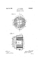
- Fig. 1 is an elevational and partial sectional view of one form of the invention
- FFig. 2 is a view along the line 2 2 of -grhe drawings illustrate onevembodiment of my invention.
- I have shown therein a radiator unit comprising a generally oblong lshaped casing 39 adapted as a closed receptacle for aheating fluid and a plurality of air circulating tubes 45 extending therethrough.
- An intake pipe 43 delivers heated Huidinto the crescent shaped portion 41 from which 65 it travels'around and downwardly between the tubes 45, into the crescent shaped por-r tion 42 and out through a discharge pipe 44.
- the tubes45 are preferably positioned so that the fluid in ⁇ travelling downwardly travv els a devious path'. The fluid isthereby retarded in its motion suhciently so that it loses ⁇ the greater portion of its heat through the tubes 45.
- 4 l y Bars 47 are provided to support the motor 75 46.y The bars 47 are for this purpose fastened to the wall ofthe casing 39 and tothe motor 46 by a plurality of bolts' 53.
- a fan 48 is operatively connected with the motor 46 bly a shaft 54.
- lAn annular shaped guard p ate 49 surrounds the fan 48.
- a deflecting device comprising a plurality of vanes 50 is mounted on the guard plate 49.
- the vanes 50 and therod 51 areconnected by a pluralityof rings 52.
- The. upper crescent like portion of the tank which has no tubes extending transversely therethrough ermits the unimpeded llow of the 'heating uid downwardly around the outside of the tubes occupying the upperv half of the casing and permits a substantially uniform flow of fluid downwardly around the tubes.
- the lower crescent shaped portion 42 provides a receptacle towards which the fluid iows downwardly in a generally radial direction from the middle of the casing.
- the radial paths are less obstructed by tubes 45 and thel fluid meets with less resistance to flow along these lines by reason of the surrounding portions of the tank untraversed by tubes 45.
- a further advantage ofthe generally annular varrangement of the tubes 45 through an elongated casing, is that the device can be constructed very compactly.
- the open space left in the middle of the casing is made suiiiciently large to accommodate the motor 46.
- 14A device of the class described comprising an elongated casing through which heating iuid is caused to travel, a plurality of air circulating tubes traversing said casing, said tubes being arranged in annular formation and having fluid circulating passages therebetween, the ⁇ .ends of said casing being generally crescent shaped and untraversed by air circulating tubes.
- a device of the class described comprising an elongated casing through which heating iuid .is caused to travel, a pluralityl of air circulating -tubes traversing said casing, said tubes being arranged in annular formation and having water circulating passages therebetween, the ends of said casing being generally crescent shaped and untraversed by air circulating tubes, a cylindrical wall centrally mounted in said casing, an electric motor mounted within said cylindrical wall, and a fan operable by the motor to circulate air through said tubes.
- a device of the class described comprising an elongated casing through which heating fluid is caused to travel, a plurality of air circulating tubes traversing said casing, said tubes being arranged in l'annular formation and having water circulating passages therebetween, the ends of said casing being generally crescent shaped and untraversed by air.
- circulating tubes a-cylindrical wall centrally mounted inV said casing, an electric motor mounted within said wall, a fan operable by the motor to circulate Aair through said tubes and delecting means operable to control' the direction of the flow of the air set in motion by the fan.
- a device of the class described comprising an" elongated casing through which heating fluid is caused to travel, a plurality of air circulating tubes traversing said casing' said tubes being arranged in annular formation and having water circulating passages therebetween the ends of said casing being generally crescent shaped and untraversed by air circulating tubes, a cylindrical wall centrally mounted in said casing, an electric motor mounted within said cylindrical wall, a fan operable by the motor to circulate air to said tubes, and deilecting means operable to control the direction and volume of air set in motion by the fan.
- a device of the class described comprising an elongated casing, a plurality of air circulating tubes traversing said casing said tubes being arranged in annular formation and having fluid circulating passages therebetween the ends of said casing being generally crescent shaped and untraversed by air circulating tubes, an inlet pipe opening into one of said crescent shaped vends and an outlet pipe opening out of the other of said crescent shaped ends.
- a device of the class described comprising an elongated vertical casing through which heating fluid is caused to travel, a plurality of air circulating tubes traversing said casing. said tubes being arranged in annular formation and having water circulating passages therebetween, the upper and lower portions of said casing being generally crescent shaped and untraversed by air circulating tubes, a fluid supply pipe opening into the upper crescent shaped portion, a
- a device of the class described comprising an elongated vertical casing through which heating fluid is caused to travel, a plurality of air circulating tubes traversing the casing said tubes being arranged in annular formation and having water circulating passages therebetween, the upper and lower portions of said casing being generally crescent shaped and untraversed by air circulating tubes,'an inlet pipe leading out of the other end of the casing, a cylindrical wall centrally mounted in said casing, an electric motor mounted within said cylindricalwall, a fan operable by the motor to circulate air through said air circulating ,passages and deecting means operable to control the volume and the Slilreption of the flow of air set in motion by e an.
- a device of the class described comprising an elongated casing through which heatioo ing fluid is caused to travel, a plurality of air circulating tubes traversing said casing, said tubes having fluid circulating passa es therebetween, the ends ofthe saidcasing ing untrave'rsed by air circulating tubes, vern A tically aligned inlet and outlet passages communicating with said ends whereby fiuid may be introduced to and circulated throu h said casing and means for advancing air t rough said tubes.
Landscapes
- Engineering & Computer Science (AREA)
- Physics & Mathematics (AREA)
- Thermal Sciences (AREA)
- Mechanical Engineering (AREA)
- General Engineering & Computer Science (AREA)
- Heat-Exchange Devices With Radiators And Conduit Assemblies (AREA)
- Domestic Hot-Water Supply Systems And Details Of Heating Systems (AREA)
Description
April 19, 1932. A. B. MoDlNE HEATING APPARATUS Filed Feb. 23, 1929 'Patented Apr. 19, 1932 UNITEDI STATES vP-AilaNrr"olfFlcE ARTHURv MODINE, RACINE, WISCONSIN, ASSIGNORTO MODINE MANUFACTURING COMPANY, F RACINE, WISCONSIN, A CORPORATION OF WISCONSIN HEATING APPARATUS Appncatibn mea february 2a, 192s. serial No. 342,284.
My invention relates to an improved heat exchange apparatus adapted for,4 heating buildings, automobiles, dryers or ,the like.
One object of the invention is to provide im- 'gj proved apparatus comprising a plurality of air circulating passages interspersed by water or steam circulating passages and having means incorporated therewith for forcibly driving air through the air passages for heating the air and for circulating the heated air throughout spaces to be heated,
lor about and upon articles tobe dried;
A still further object is the provision of improved heat exchange apparatus for controlling the direction and the volume of the heated air discharged therefrom.
Another object ofthe invention is to provide heatingapparatus of the class described which is so constructed as to be Very compact and small in4 size, thereby taking up very little space and particularly adapting it for installation. in' va vehicle.
Many other objects and advantages of the l construction herein shown and described will be obvious to those skilled in the art -from the disclosure herein-given.
To this end my invention consists in the novel construction, arrangement and combination'of--parts herein shown and described,
and more particularly pointed out in the claims.v
The drawings disclose structure designed to carry out the Various objects of the invention butl it is to be understood thatv the in- 36 vention is not confined to the exact features shown, as various changes may be nade in the x scope of the claims which follow.
In the drawings, wherein, like reference characters .indicate 'like or corresponding ,40 parts Fig. 1 is an elevational and partial sectional view of one form of the invention; and FFig. 2 is a view along the line 2 2 of -grhe drawings illustrate onevembodiment of my invention. I have shown therein a radiator unit comprising a generally oblong lshaped casing 39 adapted as a closed receptacle for aheating fluid and a plurality of air circulating tubes 45 extending therethrough.
drawn past the vanes 50 and driven in the in spaced 'relation in a generally annular for- 55 mation about the member 40. The tubes '45 'are arranged substantially symmetrical about the member 40. The annular arrangement of the tubes 45 leaves an upper crescent shaped portion 41 of the casing 39 un- .60 traversed by tubes and a corresponding lower crescent' shaped portion 42,I likewise untraversed by tubes. I Y
An intake pipe 43 delivers heated Huidinto the crescent shaped portion 41 from which 65 it travels'around and downwardly between the tubes 45, into the crescent shaped por-r tion 42 and out through a discharge pipe 44. The tubes45 are preferably positioned so that the fluid in` travelling downwardly travv els a devious path'. The fluid isthereby retarded in its motion suhciently so that it loses` the greater portion of its heat through the tubes 45. 4 l y Bars 47 are provided to support the motor 75 46.y The bars 47 are for this purpose fastened to the wall ofthe casing 39 and tothe motor 46 by a plurality of bolts' 53. A fan 48 is operatively connected with the motor 46 bly a shaft 54. lAn annular shaped guard p ate 49 surrounds the fan 48. A deflecting device comprising a plurality of vanes 50 is mounted on the guard plate 49. The vanes 50 and therod 51 areconnected by a pluralityof rings 52. l y
It is obvious that rotation of the fan in one direction will operate to draw air through the tubes 45 and that such air in passin through the tubes 45 is heated by the iuid ontained in the casing-39 and then trav- 00 els out through the guard member 49 and between deflectors 50. Rotation of the fan in the opposite direction will cause air to be opposite direction through the tubes 45, "A- 0., plate 55 is positioned between the fan 48 and the motor 46 to insulate the motor from the heated air set in motionI by the fan.
The. upper crescent like portion of the tank which has no tubes extending transversely therethrough ermits the unimpeded llow of the 'heating uid downwardly around the outside of the tubes occupying the upperv half of the casing and permits a substantially uniform flow of fluid downwardly around the tubes. The lower crescent shaped portion 42 provides a receptacle towards which the fluid iows downwardly in a generally radial direction from the middle of the casing. The radial paths are less obstructed by tubes 45 and thel fluid meets with less resistance to flow along these lines by reason of the surrounding portions of the tank untraversed by tubes 45. A further advantage ofthe generally annular varrangement of the tubes 45 through an elongated casing, is that the device can be constructed very compactly. The open space left in the middle of the casing is made suiiiciently large to accommodate the motor 46. y l
Having thus described my invention it is obvious that various immaterial modifications may be made in the same without departing from the spirit of my invention; hence I do not wish to be understood as limiting myself to the exact form, construction, arrangement and combination of parts herein shown and described, or uses mentioned.
What I claim as new and desire to secure by Letters Patent is:
14A device of the class described comprising an elongated casing through which heating iuid is caused to travel, a plurality of air circulating tubes traversing said casing, said tubes being arranged in annular formation and having fluid circulating passages therebetween, the`.ends of said casing being generally crescent shaped and untraversed by air circulating tubes.
2. A device of the class described comprising an elongated casing through which heating iuid .is caused to travel, a pluralityl of air circulating -tubes traversing said casing, said tubes being arranged in annular formation and having water circulating passages therebetween, the ends of said casing being generally crescent shaped and untraversed by air circulating tubes, a cylindrical wall centrally mounted in said casing, an electric motor mounted within said cylindrical wall, and a fan operable by the motor to circulate air through said tubes.
3. A device of the class described comprising an elongated casing through which heating fluid is caused to travel, a plurality of air circulating tubes traversing said casing, said tubes being arranged in l'annular formation and having water circulating passages therebetween, the ends of said casing being generally crescent shaped and untraversed by air. circulating tubes, a-cylindrical wall centrally mounted inV said casing, an electric motor mounted within said wall, a fan operable by the motor to circulate Aair through said tubes and delecting means operable to control' the direction of the flow of the air set in motion by the fan.
4. A device of the class described comprising an" elongated casing through which heating fluid is caused to travel, a plurality of air circulating tubes traversing said casing' said tubes being arranged in annular formation and having water circulating passages therebetween the ends of said casing being generally crescent shaped and untraversed by air circulating tubes, a cylindrical wall centrally mounted in said casing, an electric motor mounted within said cylindrical wall, a fan operable by the motor to circulate air to said tubes, and deilecting means operable to control the direction and volume of air set in motion by the fan.
5. A device of the class described comprising an elongated casing, a plurality of air circulating tubes traversing said casing said tubes being arranged in annular formation and having fluid circulating passages therebetween the ends of said casing being generally crescent shaped and untraversed by air circulating tubes, an inlet pipe opening into one of said crescent shaped vends and an outlet pipe opening out of the other of said crescent shaped ends.
6. A device of the class described comprising an elongated vertical casing through which heating fluid is caused to travel, a plurality of air circulating tubes traversing said casing. said tubes being arranged in annular formation and having water circulating passages therebetween, the upper and lower portions of said casing being generally crescent shaped and untraversed by air circulating tubes, a fluid supply pipe opening into the upper crescent shaped portion, a
fluid discharge pipe leading from said lowerl crescent shaped portions, a cylindrical wall centrally mounted .in said casing, an electric motor mounted within said cylindrical wall, and a fan operable by the motor to circulate air through said air circulating passages.
7. A device of the class described comprising an elongated vertical casing through which heating fluid is caused to travel, a plurality of air circulating tubes traversing the casing said tubes being arranged in annular formation and having water circulating passages therebetween, the upper and lower portions of said casing being generally crescent shaped and untraversed by air circulating tubes,'an inlet pipe leading out of the other end of the casing, a cylindrical wall centrally mounted in said casing, an electric motor mounted within said cylindricalwall, a fan operable by the motor to circulate air through said air circulating ,passages and deecting means operable to control the volume and the Slilreption of the flow of air set in motion by e an.
8. A device of the class described comprising an elongated casing through which heatioo ing fluid is caused to travel, a plurality of air circulating tubes traversing said casing, said tubes having fluid circulating passa es therebetween, the ends ofthe saidcasing ing untrave'rsed by air circulating tubes, vern A tically aligned inlet and outlet passages communicating with said ends whereby fiuid may be introduced to and circulated throu h said casing and means for advancing air t rough said tubes.
In witness whereof, I hereunto subscribe my name this 20th day of February, A. D.
ARTHUR B. MODINE.
Priority Applications (2)
| Application Number | Priority Date | Filing Date | Title |
|---|---|---|---|
| US342284A US1854213A (en) | 1929-02-23 | 1929-02-23 | Heating apparatus |
| US450726A US1872785A (en) | 1929-02-23 | 1930-05-08 | Heat exchange device |
Applications Claiming Priority (1)
| Application Number | Priority Date | Filing Date | Title |
|---|---|---|---|
| US342284A US1854213A (en) | 1929-02-23 | 1929-02-23 | Heating apparatus |
Publications (1)
| Publication Number | Publication Date |
|---|---|
| US1854213A true US1854213A (en) | 1932-04-19 |
Family
ID=23341147
Family Applications (1)
| Application Number | Title | Priority Date | Filing Date |
|---|---|---|---|
| US342284A Expired - Lifetime US1854213A (en) | 1929-02-23 | 1929-02-23 | Heating apparatus |
Country Status (1)
| Country | Link |
|---|---|
| US (1) | US1854213A (en) |
Cited By (1)
| Publication number | Priority date | Publication date | Assignee | Title |
|---|---|---|---|---|
| US2721730A (en) * | 1952-04-22 | 1955-10-25 | Lorraine Carbone | Heat exchanger |
-
1929
- 1929-02-23 US US342284A patent/US1854213A/en not_active Expired - Lifetime
Cited By (1)
| Publication number | Priority date | Publication date | Assignee | Title |
|---|---|---|---|---|
| US2721730A (en) * | 1952-04-22 | 1955-10-25 | Lorraine Carbone | Heat exchanger |
Similar Documents
| Publication | Publication Date | Title |
|---|---|---|
| US2346410A (en) | Unit heater | |
| US2206858A (en) | Ventilating apparatus | |
| US2862434A (en) | Ventilation system | |
| US1853333A (en) | Heater for motor vehicles | |
| US1854213A (en) | Heating apparatus | |
| US2903247A (en) | Radiators of the baseboard type | |
| US3203476A (en) | Air diffuser and dispenser for automtive vehicles | |
| US1884095A (en) | Heat exchange device | |
| US2349683A (en) | Heat exchange device | |
| US3151671A (en) | Radiator assembly with booster control | |
| US2503667A (en) | Heat exchanger | |
| US2134881A (en) | Air conditioning device | |
| US1031489A (en) | System of heating. | |
| US1936914A (en) | Air circulating system | |
| US2903245A (en) | Baseboard radiators | |
| US1403319A (en) | Heat-exchange apparatus | |
| US1849396A (en) | Air heater | |
| US1879072A (en) | Heating apparatus for automotive vehicles | |
| US2132294A (en) | Heater | |
| US1637276A (en) | Heat-exchanging apparatus | |
| US1726275A (en) | Heating apparatus | |
| US1668537A (en) | Matthias xiurxxn | |
| US1906994A (en) | Heating and ventilating device | |
| US10704494B2 (en) | Heat recovery structure | |
| US1941587A (en) | Indirect heat exchanger |