US1856486A - Sewing kit - Google Patents
Sewing kit Download PDFInfo
- Publication number
- US1856486A US1856486A US397528A US39752829A US1856486A US 1856486 A US1856486 A US 1856486A US 397528 A US397528 A US 397528A US 39752829 A US39752829 A US 39752829A US 1856486 A US1856486 A US 1856486A
- Authority
- US
- United States
- Prior art keywords
- base
- thread
- column
- spool
- fixed
- Prior art date
- Legal status (The legal status is an assumption and is not a legal conclusion. Google has not performed a legal analysis and makes no representation as to the accuracy of the status listed.)
- Expired - Lifetime
Links
- 238000009958 sewing Methods 0.000 title description 8
- 239000004744 fabric Substances 0.000 description 2
- 239000002184 metal Substances 0.000 description 2
- 241000226585 Antennaria plantaginifolia Species 0.000 description 1
- 238000010276 construction Methods 0.000 description 1
- 239000000463 material Substances 0.000 description 1
Images
Classifications
-
- D—TEXTILES; PAPER
- D05—SEWING; EMBROIDERING; TUFTING
- D05B—SEWING
- D05B91/00—Tools, implements, or accessories for hand sewing
- D05B91/14—Thread-spool pins
Definitions
- This invention relates to improvements insewing kits and more particularly to receptacles for sewing accessories.
- the principal object of the invention is to provide a convenient means for assembling sewing articles so that they are individually accessible.
- Another object is to provide holders for spools of thread arranged to prevent en- 19 tanglement of the thread ends.
- Figure 1 is a vertical section of a sewing kit constructed in accordance with this in- J vention.
- Figure 2 is a horizontal section of the same on the line II-II, Figure 1.
- Figure 3 is an enlarged detail plan view of the thread holding and cutting attachment.
- FIG. 1 Figure 4 is a front view of the same.
- Figure 5 is a detached detail of the pin cushion attachment.
- Figure 6 is a modified form of combined spool holder, and thread holder and cutter.
- Figure 7 is a front view of the same.
- Figure 8 is a plan View of the same.
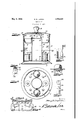
- the construction illustrated in the drawings comprises the base, preferably die formed or spun in sheet metal.
- This base has the curled edge 1, the flat top 2, and the annular wall 3.
- the tubular column 4 is fixed to the top 2 to form the central compartment 5.
- the top of this tube is cured inward as at 6.
- a shallow tray surrounds and is fixed to the tube 4 near its top and has the bottom 7 and annular wall 8, with a curled edge as at 9.
- the spool pegs 10 are arranged in acircle around the tube 4 and fixed in the top 2 of may be made up with the disc 24 tied in, then Serial No. 397,528.
- the base These pegs 10 have the heads 11 thereon, projecting above the spools 12.
- the heads of the pegs are of a diameter slightly less than the diameter of the standard hole in f V spools, so that the spools must be centered before they can be removed from the pegs, as will hereinafter be more fully described.
- the enclosing case consists of a cylindrical wall 13, snugly and frictionally engaging the. wall 3 of the base.
- the top 14 may be or-' namental sheet metal, provided with the knob 15, or other form of handle.
- the top 14 is joined to the wall 13 in any suitable manner, such as the clips 16' engaging within the curled edge 17 of the top and clinched through the wall 13.
- the spring clip 18 is fixed to the underside of the top 14 and has the spring extensions 19-19 with the latch ends 20-20 resiliently, engaging under the curled edge 6 of the central tube 4, to detachably attach the enclosing case to the base.
- the edge 9 of the tray fits closely enough within the case to prevent lateral movement of the case on the base, so that the case can only be detached by a longitudinal pull against the latches 20-20.
- the base top 2 is provided with holes to receive the cushions 21-21. These cushions are made of a section of cloth folded over a fibrous center 22. The ends 23 of the cloth are pushed through the hole in the base 2, then spread out to receive the cardboard disc '24. The ends 23 are then drawn to the center and tied under the disc 24. The cushion the cushion forced upward through the hole in the base 2. Two cushions are desirable, one for pins, the other for threaded needles.
- the thread holding and cutting clip shown in Figure 4 consists of the opposed plates 25, 26, riveted or welded to the wall 8 of the tray at intervals between and above the spools 12.
- These plates are preferably of spring material, the outer plate 25, being provided with the notches 27-27 through which the thread ends 28-28 extend after passing between the plates, which frictionally bind the thread between them.
- the desired length of thread withdrawn from the spool 12 is. then passed down into the V shape cutter notch 29 and severed. This leaves an end of thread equal to the distance between the notches 27, 29.
- the thread being withdrawn from the spool may tend to lift the spool from the base 2. But any lifting tendency against the spool is from the periphery, Which lifts the spool obliquely, causing it to impinge under the head 11, and preventing its dislodgment from the pin 10.
- a modified form of spoolholder is shown in Figures 6, 7, 8, consisting of the plate 30 adapted to be fixed to the base 2.
- One end of this plate is laterally slit and curled into the spindle 31, which is bent upright to engage the hole in the spool.
- the other end is bent upright to form the guide 32, provided with the slotted guidehole in one edge.
- the thread end 28 is passed I through this hole and carried upward and drawn down behind the cutter 34 and the desired length severed therein.
- the concave portion .35 is provided as a convenience in grasping the length of thread extending from 3, the hole 33 and confined behind the cutter 84.
- The'central compartment 5 is a convenient holder for scissors and similar tools.
- the tray is for thimbles, buttons and notions.
- the cylindrical form is preferred because it is easier to fabricate, but other forms-are adaptable without departing from the spirit of this invention.
- a sewing hit comprising a base, a compartment column fixed to said base, a tray fixed to said column, a casing adapted to enclose said column and engage said base, a
- a sewing kit comprising a base, a compartment column fixed to said base, a tray fixed to said column, an annular casing en- 4 circling said column and adapted to frictionally engage said base, a top fixed to said casing, and a resilient latch depending from said top and engaging the upper end of said column.
- a sewing kit comprising a base, a com- I artment column fixed to said base, an annuar tray fixed to said column, spool holders arranged around said column, thread holding means on said tray for each of said spool holders, said thread holders comprising thread holding plate overlying a resilient 1 plate ada-pted to clamp the thread ends, a casing enclosing said column and spool holders, and a resilient latch depending from said casing and engaging said column.
Landscapes
- Engineering & Computer Science (AREA)
- Textile Engineering (AREA)
- Sewing Machines And Sewing (AREA)
Description
y 1932. H. D. LAPKIN 1,856,486
SEWING KIT Filed Oct. 5, 1929 Patented May 3, 1932 UH'I'ED STATES HARRY D. LAPKIN, OF SAN FRANCISCO, CALIFORNIA SEWING KIT Application filed October 5, 1929.
This invention relates to improvements insewing kits and more particularly to receptacles for sewing accessories.
The principal object of the invention is to provide a convenient means for assembling sewing articles so that they are individually accessible.
Another object is to provide holders for spools of thread arranged to prevent en- 19 tanglement of the thread ends. Other objects and advantages will appear as the description progresses.
In this specification and the accompanylng drawings the invention is disclosed in its preferred form. But it is to be understood that it is not limited to such form because it can be embodied in other forms. It is also to be understood that in and by the claims following the description it is desired to cover the invention in whatsoever form it may be embodied.
In the one sheet of drawings:
Figure 1 is a vertical section of a sewing kit constructed in accordance with this in- J vention.
Figure 2 is a horizontal section of the same on the line II-II, Figure 1.
Figure 3 is an enlarged detail plan view of the thread holding and cutting attachment.
1 Figure 4 is a front view of the same.
Figure 5 is a detached detail of the pin cushion attachment.
Figure 6 is a modified form of combined spool holder, and thread holder and cutter.
Figure 7 is a front view of the same, and
Figure 8 is a plan View of the same.
In detail the construction illustrated in the drawings comprises the base, preferably die formed or spun in sheet metal. This base has the curled edge 1, the flat top 2, and the annular wall 3.
The tubular column 4 is fixed to the top 2 to form the central compartment 5. The top of this tube is cured inward as at 6. A shallow tray surrounds and is fixed to the tube 4 near its top and has the bottom 7 and annular wall 8, with a curled edge as at 9.
The spool pegs 10 are arranged in acircle around the tube 4 and fixed in the top 2 of may be made up with the disc 24 tied in, then Serial No. 397,528.
the base. These pegs 10 have the heads 11 thereon, projecting above the spools 12. The heads of the pegs are of a diameter slightly less than the diameter of the standard hole in f V spools, so that the spools must be centered before they can be removed from the pegs, as will hereinafter be more fully described. The enclosing case consists of a cylindrical wall 13, snugly and frictionally engaging the. wall 3 of the base. The top 14 may be or-' namental sheet metal, provided with the knob 15, or other form of handle.
The top 14 is joined to the wall 13 in any suitable manner, such as the clips 16' engaging within the curled edge 17 of the top and clinched through the wall 13.
The spring clip 18 is fixed to the underside of the top 14 and has the spring extensions 19-19 with the latch ends 20-20 resiliently, engaging under the curled edge 6 of the central tube 4, to detachably attach the enclosing case to the base. The edge 9 of the tray fits closely enough within the case to prevent lateral movement of the case on the base, so that the case can only be detached by a longitudinal pull against the latches 20-20.
The base top 2 is provided with holes to receive the cushions 21-21. These cushions are made of a section of cloth folded over a fibrous center 22. The ends 23 of the cloth are pushed through the hole in the base 2, then spread out to receive the cardboard disc '24. The ends 23 are then drawn to the center and tied under the disc 24. The cushion the cushion forced upward through the hole in the base 2. Two cushions are desirable, one for pins, the other for threaded needles.
The thread holding and cutting clip shown in Figure 4, consists of the opposed plates 25, 26, riveted or welded to the wall 8 of the tray at intervals between and above the spools 12.
These plates are preferably of spring material, the outer plate 25, being provided with the notches 27-27 through which the thread ends 28-28 extend after passing between the plates, which frictionally bind the thread between them. The desired length of thread withdrawn from the spool 12 is. then passed down into the V shape cutter notch 29 and severed. This leaves an end of thread equal to the distance between the notches 27, 29.
The thread being withdrawn from the spool, may tend to lift the spool from the base 2. But any lifting tendency against the spool is from the periphery, Which lifts the spool obliquely, causing it to impinge under the head 11, and preventing its dislodgment from the pin 10.
A modified form of spoolholder is shown in Figures 6, 7, 8, consisting of the plate 30 adapted to be fixed to the base 2. One end of this plate is laterally slit and curled into the spindle 31, which is bent upright to engage the hole in the spool. The other end is bent upright to form the guide 32, provided with the slotted guidehole in one edge. The thread end 28 is passed I through this hole and carried upward and drawn down behind the cutter 34 and the desired length severed therein. The concave portion .35; is provided as a convenience in grasping the length of thread extending from 3, the hole 33 and confined behind the cutter 84.
The'central compartment 5 is a convenient holder for scissors and similar tools. The tray is for thimbles, buttons and notions. ,The cylindrical formis preferred because it is easier to fabricate, but other forms-are adaptable without departing from the spirit of this invention.
Having thus described this invention What is Claimed and. desired to cover by Letters .3 Patent is 1. A sewing hit comprising a base, a compartment column fixed to said base, a tray fixed to said column, a casing adapted to enclose said column and engage said base, a
latch on said casing adapted to engage said column.
2. A sewing kit comprising a base, a compartment column fixed to said base, a tray fixed to said column, an annular casing en- 4 circling said column and adapted to frictionally engage said base, a top fixed to said casing, and a resilient latch depending from said top and engaging the upper end of said column. a
' 3. A sewing kit comprising a base, a com- I artment column fixed to said base, an annuar tray fixed to said column, spool holders arranged around said column, thread holding means on said tray for each of said spool holders, said thread holders comprising thread holding plate overlying a resilient 1 plate ada-pted to clamp the thread ends, a casing enclosing said column and spool holders, and a resilient latch depending from said casing and engaging said column. I
In testimony whereof I have hereunto set my hand this SOth'day of September A. D.
" HARRY D. LAPKIN.
Priority Applications (1)
| Application Number | Priority Date | Filing Date | Title |
|---|---|---|---|
| US397528A US1856486A (en) | 1929-10-05 | 1929-10-05 | Sewing kit |
Applications Claiming Priority (1)
| Application Number | Priority Date | Filing Date | Title |
|---|---|---|---|
| US397528A US1856486A (en) | 1929-10-05 | 1929-10-05 | Sewing kit |
Publications (1)
| Publication Number | Publication Date |
|---|---|
| US1856486A true US1856486A (en) | 1932-05-03 |
Family
ID=23571550
Family Applications (1)
| Application Number | Title | Priority Date | Filing Date |
|---|---|---|---|
| US397528A Expired - Lifetime US1856486A (en) | 1929-10-05 | 1929-10-05 | Sewing kit |
Country Status (1)
| Country | Link |
|---|---|
| US (1) | US1856486A (en) |
Cited By (4)
| Publication number | Priority date | Publication date | Assignee | Title |
|---|---|---|---|---|
| US2673669A (en) * | 1952-07-18 | 1954-03-30 | Hawkins Raymond Eugene | Portable sewing box |
| US2675949A (en) * | 1950-03-04 | 1954-04-20 | Chicago Lighthouse For The Bli | Sewing basket |
| USD286370S (en) | 1984-05-17 | 1986-10-28 | Mossberg Industries, Inc. | Wire de-reeling pail |
| US11441248B2 (en) * | 2016-10-25 | 2022-09-13 | Prym Consumer Usa Inc. | Yarn-carrying and dispensing apparatus |
-
1929
- 1929-10-05 US US397528A patent/US1856486A/en not_active Expired - Lifetime
Cited By (4)
| Publication number | Priority date | Publication date | Assignee | Title |
|---|---|---|---|---|
| US2675949A (en) * | 1950-03-04 | 1954-04-20 | Chicago Lighthouse For The Bli | Sewing basket |
| US2673669A (en) * | 1952-07-18 | 1954-03-30 | Hawkins Raymond Eugene | Portable sewing box |
| USD286370S (en) | 1984-05-17 | 1986-10-28 | Mossberg Industries, Inc. | Wire de-reeling pail |
| US11441248B2 (en) * | 2016-10-25 | 2022-09-13 | Prym Consumer Usa Inc. | Yarn-carrying and dispensing apparatus |
Similar Documents
| Publication | Publication Date | Title |
|---|---|---|
| US2501357A (en) | Pocket-size tissue container | |
| US1856486A (en) | Sewing kit | |
| US1886752A (en) | Stand | |
| US2417421A (en) | Portable carrier | |
| US2460530A (en) | Container carrier | |
| US1998232A (en) | Holder for collapsible tubes and the like | |
| US1762977A (en) | Sundae dish and holder and method of assembling the same | |
| US2550944A (en) | Holder for a spool of thread | |
| US2117404A (en) | Holder for twin pails | |
| US2177993A (en) | Receptacle and carrier therefor | |
| US2822208A (en) | Carrying device for containers | |
| US2673669A (en) | Portable sewing box | |
| US2148860A (en) | Thread dispenser | |
| US2275545A (en) | Crochet kit | |
| US4330095A (en) | Free standing, multiple skein yarn holder and dispenser | |
| US1858639A (en) | Top | |
| US2231364A (en) | Indicia holder for cosmetic containers | |
| US2273642A (en) | Brush supporting device | |
| US2461748A (en) | Christmas tree stand or holder | |
| US2144825A (en) | Knitting appliance | |
| US2033640A (en) | Container | |
| US2923451A (en) | Sewing accessory | |
| US2121676A (en) | Multiple purpose sewing equipment holder | |
| US2675949A (en) | Sewing basket | |
| US2226430A (en) | Thread holder |