US1856473A - Checkerwork - Google Patents
Checkerwork Download PDFInfo
- Publication number
- US1856473A US1856473A US429914A US42991430A US1856473A US 1856473 A US1856473 A US 1856473A US 429914 A US429914 A US 429914A US 42991430 A US42991430 A US 42991430A US 1856473 A US1856473 A US 1856473A
- Authority
- US
- United States
- Prior art keywords
- bricks
- checker
- portions
- bridge
- rows
- Prior art date
- Legal status (The legal status is an assumption and is not a legal conclusion. Google has not performed a legal analysis and makes no representation as to the accuracy of the status listed.)
- Expired - Lifetime
Links
- 239000011449 brick Substances 0.000 description 86
- 238000010276 construction Methods 0.000 description 16
- 238000010438 heat treatment Methods 0.000 description 8
- 238000004519 manufacturing process Methods 0.000 description 6
- 239000000463 material Substances 0.000 description 5
- 230000003247 decreasing effect Effects 0.000 description 4
- 238000009825 accumulation Methods 0.000 description 2
- 239000007789 gas Substances 0.000 description 2
- 230000002441 reversible effect Effects 0.000 description 2
- 239000011717 all-trans-retinol Substances 0.000 description 1
- 238000004140 cleaning Methods 0.000 description 1
- 206010022000 influenza Diseases 0.000 description 1
- 239000002245 particle Substances 0.000 description 1
- 229920000136 polysorbate Polymers 0.000 description 1
- 230000001172 regenerating effect Effects 0.000 description 1
- 230000000284 resting effect Effects 0.000 description 1
- 239000011343 solid material Substances 0.000 description 1
Images

Classifications
-
- C—CHEMISTRY; METALLURGY
- C21—METALLURGY OF IRON
- C21B—MANUFACTURE OF IRON OR STEEL
- C21B9/00—Stoves for heating the blast in blast furnaces
- C21B9/02—Brick hot-blast stoves
- C21B9/06—Linings
-
- Y—GENERAL TAGGING OF NEW TECHNOLOGICAL DEVELOPMENTS; GENERAL TAGGING OF CROSS-SECTIONAL TECHNOLOGIES SPANNING OVER SEVERAL SECTIONS OF THE IPC; TECHNICAL SUBJECTS COVERED BY FORMER USPC CROSS-REFERENCE ART COLLECTIONS [XRACs] AND DIGESTS
- Y10—TECHNICAL SUBJECTS COVERED BY FORMER USPC
- Y10S—TECHNICAL SUBJECTS COVERED BY FORMER USPC CROSS-REFERENCE ART COLLECTIONS [XRACs] AND DIGESTS
- Y10S165/00—Heat exchange
- Y10S165/009—Heat exchange having a solid heat storage mass for absorbing heat from one fluid and releasing it to another, i.e. regenerator
- Y10S165/013—Movable heat storage mass with enclosure
- Y10S165/016—Rotary storage mass
- Y10S165/02—Seal and seal-engaging surface are relatively movable
- Y10S165/021—Seal engaging a face of cylindrical heat storage mass
Definitions
- the present invention relates broadly to the art of checker work for regenerative fur naces', hot blast stoves and the like, and more particularly to an improved construction of 51 checker work andimproved checker bricks for use therein.
- checkers in accordance with a number of more'or less standard designs. These designs are of such widely diiferent characteristics as to afford from 2.54 square feet of exposed heating surface per cubic foot of checker work to 6.1 square feet of exposed heating surface per cubic foot of checker work. With a typical construction in which the smaller number of square feet of heating surface is provided, there is available .49 square foot of free area per square foot of horizontal checker area, while with the construction affording greater heating surface there is but .29 square foot of free area per square foot of horizontal checker area.
- the present construction affords a vertical flue'of maximum dimensions, thereby permitting a free flow of the gases through the checker.
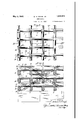
- Figure 1 is a perspective view illustrating one type of construction in which the longitudinal and transverse rows are directly superimposed throughout the entire checker area
- Figure 2 is a View similar to Figure 1 illustrating a slightly modified construction in which the longitudinal bricks are directly superimposed, but in which the transverse bricks are staggered in alternate courses,
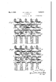
- FIG. 3 is atop plan view of a portion of a checker constructed in accordance with the disclosure of Figure 1,
- Figure 4 is a vertical sectional view on the line IVIV of Figure 3,
- Figure 5 is a vertical'sectional view on the line VV of Figure 3,
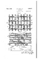
- Figure 6 is a view similar to Figure 3 illustrating in plan a checker constructed inaccordance with the showing of Figure 2,
- Figure 7 is a vertical sectional view on the line VIIVII of Figure 6, and
- Figure 8 is a vertical sectional view on the line VIIIVIII of Figure 6.
- the bridge bricks B each comprises an intermediate body section with a head 2 formed on each end thereof.
- the intermediate body portion is formed 'to provide oppositelyinclined upper and lower edges 3,the bricks being illustrated as of 'suchflconstruction that they are reversible end for end or edge for edge.
- the upper and loweredges 4 of the heads'2 preferably provide plane. or substantially plane surfaces which are adapted to cooper- 'may bereversed end for end or edge for edge.
- Each of the. tie bricks is preferably'shaped to provide an intermediate body portion hav- 17 ing opzpositely inclined upper and lower edges These edges adjacent the ends of the bri'ck'are cutaway to provide outwardly projecting shoulders, 8 and substantially horizontally disposed shoulders 9, theportion of the ends intermediat-ethe shoulders 9 pro viding oppositely inclined surfaceslO.
- Th-e' inclination of the surfaces 10 is pref erably such as to exactly coincide with the inclination of the inclined end portions 5 of thebridge bricks B, while the width of the shoulders 9 is substantially equal to the width of the plane supporting edges 4.
- the length of each of the shoulders 9 is preferably equal to half the width of one of. the heads .2.
- a checker constructed in the manner described appears in plan substantially as illustratedin Figure 3, in which the tie bricks T constitute the longitudinal courses and the bridge bricks B the transverse courses. From this figure it will be apparent that vertical' flues F ofmaximum cross sectional area extending from the top to the bottom of the checker are afforded.
- the upper edges are shaped to provide a depression 16 intermediate the ends, which depression has a length equal to the width of the heads 2 so that each recess is adapted to cooperate with the ends of two adjacent bridge bricks.
- the interlocking engagement afforded be tween the tie bricks and the bridge bricks is the same as that heretofore described, the principal difference being that the transverse bricks lie in different vertical planes in different horizontal courses. From a consideration of Figures 7 and 8, however, it will be apparent that there is still afforded opportunity for diagonal flow through the checker, the zones 14 and 15 illustrating the direction and quantity of such flow.
- a bridge brick for checkers comprising a body portion having inclined upper and lower edges and having heads formed on each end thereof, said heads having substantially plane supporting surfaces, and also having inclined seat forming portions, the inclination of saidseat forming portions being substentially equal to the inclination of the upper and lower edges.
- tie bricks for use in checkers comprising body portions having inclined upper and lower edges, said inclined edges being cut away at predetermined portions thereof to provide substantially horizontally and vertically extending shoulders.
- bridge bricks comprising body portions having heads on each end thereof, said heads having inclined portions formed thereon,- and tie bricks having inclined upper and lower edges cooperating with such inclined portions.
- bridge bricks comprising body portions having heads on each end thereof, said heads having inclined portions formed thereon, and'tie bricks having inclined upper and lower edges cooperating with such inclined portions,: said bridge bricks and :tie bricks being shaped :to substantially interlock one withvthe other and provide flat surface engagement effective in both horizontal and vertical planes.
- each of the bricks being formed on its upper and lower surfaces with both inclined and flat contacting supporting surfaces, with the flat surfaces on an upper row resting upon the Hat surfaces of a lower row, and the inclined surfaces of the respective rows in vertically and horizontally overlapping engaging and supporting relationship.
- a refractory brick for checkersv comprising a body portion and enlarged end portions, said body portion having opposite tapered portions forming ridges, and said end portions having inclined seat forming surfaces, extending at substantially the same. angle as said ridge forming tapered portions,
- each head on each end of the body portion, each head having a pluralityof plane surfacesfor engaging other bricks in a refractory structure, at least one of said plane surfaces being inclined, said inclined surfaces extending at substantially the same angle as said ridge forming taperedportions.
- a refractory brickfor checkers comprising a body portion and enlarged end porti0ns,said body portion having opposite tapered portions forming ridges, and said end portions having plane supporting: surfaces for engaging a horizontal supporting surface with the ridges disposed atit'he top and bott'en of the br1ck,and having inclined l'surface's forengaging similarly inclined surfaces of an adjacent brick, said inclined surfaces extending at substantially the same angle as said ridge forming tapered portions.
Landscapes
- Engineering & Computer Science (AREA)
- Chemical & Material Sciences (AREA)
- Manufacturing & Machinery (AREA)
- Materials Engineering (AREA)
- Metallurgy (AREA)
- Organic Chemistry (AREA)
- Furnace Housings, Linings, Walls, And Ceilings (AREA)
Description
y 3, 1932- w. H. DRAIN, JR 73 GHECKERWORK Filed Feb. 20 1930 4 Sheets-Sheet l- INVENTOR y 1932. w. H. DRAIN, JR 1,856,473
CHECKERWORK Filed Feb. 20, 1930 4 Sheets-Sheet 3 May 3, 1932.
w. H. DRAIN, JR 1,856,473
CHECKERWORK Filed Feb. 20, 1930 4 Sheets-Sheet 4 Patented May 3, 1932 PATENT OFFICE WILLIAM H. DRAIN, an,
01' YOUNGSTOWN, OHIO GHECKERWORK Application. filed February 20, 1930. Serial No. 429,914.
7 The present invention relates broadly to the art of checker work for regenerative fur naces', hot blast stoves and the like, and more particularly to an improved construction of 51 checker work andimproved checker bricks for use therein.
In the production of checker work for uses of the character'referred to, there are certain factors which must be taken into accounting and which to a certain extent oppose each other. For example, it is desirable to provide the maximum amount of heating surface, measured in square feet, and at the same time obtain the maximum amount of free area in the checker work. It will be apparent that if the checker bricks are made larger to af ford a greater heating surface, the amount of free area will be correspondingly reduced.
At the present time it is customary to construct checkers in accordance with a number of more'or less standard designs. These designs are of such widely diiferent characteristics as to afford from 2.54 square feet of exposed heating surface per cubic foot of checker work to 6.1 square feet of exposed heating surface per cubic foot of checker work. With a typical construction in which the smaller number of square feet of heating surface is provided, there is available .49 square foot of free area per square foot of horizontal checker area, while with the construction affording greater heating surface there is but .29 square foot of free area per square foot of horizontal checker area.
The maximum of free area per square foot of horizontal checker area obtainable with standard structures is .56, this condition be ing obtained with a brick construction affording 4.03 square feet of exposed heating surface per cubic foot of checker work.
In accordance with the present invention there is provided a construction in which it is possible to obtain 5.1 square feet of exposed heating surface per cubic foot of checker work with .66'square foot of free area per square footof horizontal checker area. The advantages of such'a construction will be readilyapparent'to those skilled in the art.
In addition to'the above, the present constructionaffords a vertical flue'of maximum dimensions, thereby permitting a free flow of the gases through the checker.
Also in addition to the above, it is desirable to provide a structure in which there is free communication between the diiferent vertical lines thereby affording a more or less free passage diagonally of the entire checker. Such a diagonal flow is freely permitted by a checker constructedin accordance with the present invention.
One of the objections to checkers as ordinarily used is occasioned by the tendency of foreign material to accumulate on the checker surfaces. With bricks of the construction herein contemplated, this objection is obviated, inasmuch as the bricks have inclined upper surfaces affording a minimum area on which solid materials can collect.
In the accompanying drawings there are illustrated certain preferred embodiments of my invention.
In the drawings Figure 1 is a perspective view illustrating one type of construction in whichthe longitudinal and transverse rows are directly superimposed throughout the entire checker area,
Figure 2 is a View similar to Figure 1 illustrating a slightly modified construction in which the longitudinal bricks are directly superimposed, but in which the transverse bricks are staggered in alternate courses,
Figure 3 is atop plan view of a portion of a checker constructed in accordance with the disclosure of Figure 1,
Figure 4 is a vertical sectional view on the line IVIV of Figure 3,
Figure 5 is a vertical'sectional view on the line VV of Figure 3,
Figure 6 is a view similar to Figure 3 illustrating in plan a checker constructed inaccordance with the showing of Figure 2,
Figure 7 is a vertical sectional view on the line VIIVII of Figure 6, and
Figure 8 is a vertical sectional view on the line VIIIVIII of Figure 6.
It will be understood that the terms longitudinal and transverse as used throughout the specification and claims are purely relative terms used for purposes of description and not by way of limitation. For purposes of further facilitating a description and understanding of the invention, the bricks forming the so-called transverse courses will be designated as bridge bricks, while the bricks constituting the so-called longitudinal courses will be designatedas tie bricks, the.
respective bricks having slightly difi-erent characteristic features.
By reference more particularly to Figure 1 of the drawings, it will be apparent that the bridge bricks B each comprises an intermediate body section with a head 2 formed on each end thereof. The intermediate body portion is formed 'to provide oppositelyinclined upper and lower edges 3,the bricks being illustrated as of 'suchflconstruction that they are reversible end for end or edge for edge.- Q p The upper and loweredges 4 of the heads'2 preferably provide plane. or substantially plane surfaces which are adapted to cooper- 'may bereversed end for end or edge for edge.
Each of the. tie bricks is preferably'shaped to provide an intermediate body portion hav- 17 ing opzpositely inclined upper and lower edges These edges adjacent the ends of the bri'ck'are cutaway to provide outwardly projecting shoulders, 8 and substantially horizontally disposed shoulders 9, theportion of the ends intermediat-ethe shoulders 9 pro viding oppositely inclined surfaceslO.
' Th-e' inclination of the surfaces 10 is pref erably such as to exactly coincide with the inclination of the inclined end portions 5 of thebridge bricks B, while the width of the shoulders 9 is substantially equal to the width of the plane supporting edges 4. The length of each of the shoulders 9 is preferably equal to half the width of one of. the heads .2. By reason of this construction, it will be apparent that when the bricks are in assembled relation-to forma checker, the end surfaces '11 of the tie bricks lie substantially in. the
pl aneof the ridgelQ, intermediate the inclined upper, and lower edges 3 of the bridge bricks, while'thefiat end faces 6 of the bridge bricks liesubstantially in the plane of the ridges 13 between the inclined surfaces 7 of the tie bricks. In this position the shoulders 8 prevent endwise movement of the tie bricks, since they form'an interlocking engagement with the bridge bricks, movement of the bridge bricks being likewise prevented due to this interlocking engagement. The square 3 shoulder engagement between the tie bricks and the bridge bricks also prevents any tendency of one to tip or roll relative to the other and enables the checker to be built to any desired height.
A checker constructed in the manner described appears in plan substantially as illustratedin Figure 3, in which the tie bricks T constitute the longitudinal courses and the bridge bricks B the transverse courses. From this figure it will be apparent that vertical' flues F ofmaximum cross sectional area extending from the top to the bottom of the checker are afforded.
In Figure 4 there are indicated in shade lines zones 1 which illustrate the free flow space provided from the top to the bottom of the'checker in a diagonal'dire'ction, the fl-ow space extending above and below theibridge bricks B. By reason of the inclinedsurfaces 3 in these bricks B, greater freedom of flow in a diagonal direction is permitted than would be possible if square shoulders were utilized. At the same time, therinclined surfaces extend at a pitch such that the coefficient of friction between the same and any foreign material carried by the gases being handled is not sufficient to maintain such foreign materi-alin'position on the. surfaces. They are thus self-cleaning, whereby the life of the checker is very materially increased. This is true notfonly fort-he reason that the accumulationof foreign material and consequent clogging 'ofthe checker is prevented, but for the reason that there is not a tendency for local burningiout of the checker such 'as' occurs under an-accumulation of incandescent particles of foreign material. I 5' 1. In like manner it will be apparent from Figure 5 that a free-diagonal flow in the op- 7 posite direction is permitted. In thisffigure there are indicated in suitable shade lines diagonally extending zones 15 passing above and below the respective tie bricksT. These bricks in'like manner, due to -their inclined upper and lower edges 7, provide a maximum flow zone diagonally .of the checker and prevent the accumulation of foreign material on the checker.
natei corresponding-f parts, of the structure,
As before pointed'out, itis n possible with'this type of construction, to L The embodiment illustrated in these figures is similar to that already described with the exception that the bridge bricks B, while being of a construction identical with that heretofore described, are so disposed as to be staggered one with respect to the other in alternate courses. The tie bricks T, however, are of slightly different construction in order to accommodate the staggered arrangement of the bridge bricks. This result is obtained by making the upper and lower edges of the tie bricks of slightly different constructional characteristics. As illustrated in this figure, the lower edges of each of the tie bricks are of the same construction as that heretofore described. The upper edges, however, are shaped to provide a depression 16 intermediate the ends, which depression has a length equal to the width of the heads 2 so that each recess is adapted to cooperate with the ends of two adjacent bridge bricks. The interlocking engagement afforded be tween the tie bricks and the bridge bricks is the same as that heretofore described, the principal difference being that the transverse bricks lie in different vertical planes in different horizontal courses. From a consideration of Figures 7 and 8, however, it will be apparent that there is still afforded opportunity for diagonal flow through the checker, the zones 14 and 15 illustrating the direction and quantity of such flow.
With either type of construction it will be apparent that the'bridge bricks are in end to end abutting relationship throughout the complete area of the checker and that the same is true as to the tie bricks. This abut ting engagement between the ends of adjacent bricks further assists in maintaining the parts in the desired position.
Bricks of the character herein disclosed are capable of being easily manufactured and, due to their reversible characteristics, of being easily installed. When installed in accordance with either of the practices herein illustrated and described, they afford all of the operating advantages and characteristics which have been set forth. 7
While I have herein illustrated and described certain preferred embodiments of the invention, it will be understood that changes in the construction, arrangement and relative dimensions of the parts may be made without departing either from the spirit of my invention or the scope of my broader claims.
I claim:
1. In a checker work, superimposed courses of bricks arranged in longitudinal and transverse rows, all of said bricks having inclined upper edges, the bricks in one of said rows having enlargedheads with inclined seats cooperating with similarly inclined seats on the bricks in the other of said rows.
2. In a checker work, superimposed courses of bricks arranged in longitudinal and transverse rows, all of said bricks having inclined upper edges, the bricks in one of said rows having enlarged heads with inclined seats cooperating with similarly inclined seats on the bricks in the other of said rows, said heads also providing substantially plane supporting portions.
3. In a checker work, superimposed courses of bricks arranged in longitudinal and transverse rows, all of the bricks in one of said rows being of increased cross sectional area adjacent the ends of the bricks, and the bricks in the other row being of decreased cross sectional area adjacent the ends of the bricks, said portions of increased and decreased cross sectional area forming an interlocking engagement between the bricks preventing tilting thereof.
4;. In a checker work, superimposed courses of bricks arranged in longitudinal and transverse rows, all of said bricks having inclined upper and lower edges, the bricks in one of said rows having enlarged heads with inclined seats cooperating with inclined edges of the bricks in the other of said rows.
5. In a checker work, superimposed courses of bricks arranged. in longitudinal and transverse rows, all of said bricks having inclined upper and lower edges, the bricks in one of said. rows having enlarged heads with inclined seats cooperating with inclined edges of the bricks in the other of said rows, said heads also providing substantially plane supporting portions.
6. In a checker work, superimposed courses of bricks arranged in longitudinal and transverse rows, all of the bricks in one of said rows being of increased cross sectional area adjacent the ends of the bricks, and the bricks in the other row being of decreased cross sectional area adjacent the ends of the bricks, said portions of increased and decreased cross sectional area forming an interlocking engagment between the bricks preventing tilting thereof, all of the bricks having inclined upper and lower edges.
' 7. As an article of manufacture, a bridge brick for checkers, comprising a body portion having inclined upper and lower edges and having heads formed on each end thereof, said heads having substantially plane supporting surfaces, and also having inclined seat forming portions, the inclination of saidseat forming portions being substentially equal to the inclination of the upper and lower edges.
8. As an article of manufacture, tie bricks for use in checkers comprising body portions having inclined upper and lower edges, said inclined edges being cut away at predetermined portions thereof to provide substantially horizontally and vertically extending shoulders.
9. In a checker, bridge bricks comprising body portions having heads on each end thereof, said heads having inclined portions formed thereon,- and tie bricks having inclined upper and lower edges cooperating with such inclined portions.
10. In a checker, bridge bricks comprising body portions having heads on each end thereof, said heads having inclined portions formed thereon, and'tie bricks having inclined upper and lower edges cooperating with such inclined portions,: said bridge bricks and :tie bricks being shaped :to substantially interlock one withvthe other and provide flat surface engagement effective in both horizontal and vertical planes.
11. In a checkerwork, superimposed'courses of bricksarranged in end to end relationship in longitudinal and transverse rows, each of the bricks being formed on its upper and lower surfaces with both inclined and flat contacting supporting surfaces, with the flat surfaces on an upper row resting upon the Hat surfaces of a lower row, and the inclined surfaces of the respective rows in vertically and horizontally overlapping engaging and supporting relationship.
12. As an article of manufacture, :a refractory brick for checkersv comprising a body portion and enlarged end portions, said body portion having opposite tapered portions forming ridges, and said end portions having inclined seat forming surfaces, extending at substantially the same. angle as said ridge forming tapered portions,
13. As an article of manufacture, a.=refractory bridge brick comprising a body portion formed with tapered upper and flower sides to provide upper and lower ridges,.an.d heads,
one; on each end of the body portion, each head having a pluralityof plane surfacesfor engaging other bricks in a refractory structure, at least one of said plane surfaces being inclined, said inclined surfaces extending at substantially the same angle as said ridge forming taperedportions.
14;. As an article of manufacture, a refractory brickfor checkers comprising a body portion and enlarged end porti0ns,said body portion having opposite tapered portions forming ridges, and said end portions having plane supporting: surfaces for engaging a horizontal supporting surface with the ridges disposed atit'he top and bott'en of the br1ck,and having inclined l'surface's forengaging similarly inclined surfaces of an adjacent brick, said inclined surfaces extending at substantially the same angle as said ridge forming tapered portions.
In testimony whereof I have hereunto set myhand.
' WILLIAM H. DRAIN, JR;
Priority Applications (1)
| Application Number | Priority Date | Filing Date | Title |
|---|---|---|---|
| US429914A US1856473A (en) | 1930-02-20 | 1930-02-20 | Checkerwork |
Applications Claiming Priority (1)
| Application Number | Priority Date | Filing Date | Title |
|---|---|---|---|
| US429914A US1856473A (en) | 1930-02-20 | 1930-02-20 | Checkerwork |
Publications (1)
| Publication Number | Publication Date |
|---|---|
| US1856473A true US1856473A (en) | 1932-05-03 |
Family
ID=23705236
Family Applications (1)
| Application Number | Title | Priority Date | Filing Date |
|---|---|---|---|
| US429914A Expired - Lifetime US1856473A (en) | 1930-02-20 | 1930-02-20 | Checkerwork |
Country Status (1)
| Country | Link |
|---|---|
| US (1) | US1856473A (en) |
Cited By (6)
| Publication number | Priority date | Publication date | Assignee | Title |
|---|---|---|---|---|
| US2438814A (en) * | 1944-11-20 | 1948-03-30 | James E Macdonald | Checkerwork for furnaces |
| US2467166A (en) * | 1945-03-15 | 1949-04-12 | Gen Refractories Co | Checker-brick and checkerwork |
| USD753740S1 (en) * | 2015-01-15 | 2016-04-12 | Fosbel, Inc. | Monolithic rider arch for glass furance regenerator |
| USD754225S1 (en) * | 2015-01-15 | 2016-04-19 | Fosbel, Inc. | Monolithic crown arch for glass furance regenerator |
| US9963372B2 (en) | 2014-11-14 | 2018-05-08 | Fosbel, Inc. | Monolithic refractory crown and rider arches for glass furnace regenerators and glass furnace regenerators including the same |
| USD829248S1 (en) * | 2016-02-18 | 2018-09-25 | Fosbel, Inc. | Regenerator wall block |
-
1930
- 1930-02-20 US US429914A patent/US1856473A/en not_active Expired - Lifetime
Cited By (8)
| Publication number | Priority date | Publication date | Assignee | Title |
|---|---|---|---|---|
| US2438814A (en) * | 1944-11-20 | 1948-03-30 | James E Macdonald | Checkerwork for furnaces |
| US2467166A (en) * | 1945-03-15 | 1949-04-12 | Gen Refractories Co | Checker-brick and checkerwork |
| US9963372B2 (en) | 2014-11-14 | 2018-05-08 | Fosbel, Inc. | Monolithic refractory crown and rider arches for glass furnace regenerators and glass furnace regenerators including the same |
| USD753740S1 (en) * | 2015-01-15 | 2016-04-12 | Fosbel, Inc. | Monolithic rider arch for glass furance regenerator |
| USD754225S1 (en) * | 2015-01-15 | 2016-04-19 | Fosbel, Inc. | Monolithic crown arch for glass furance regenerator |
| USD829248S1 (en) * | 2016-02-18 | 2018-09-25 | Fosbel, Inc. | Regenerator wall block |
| USD916153S1 (en) | 2016-02-18 | 2021-04-13 | Fosbel, Inc. | Regenerator wall block |
| USD956838S1 (en) | 2016-02-18 | 2022-07-05 | Fosbel, Inc. | Regenerator wall block |
Similar Documents
| Publication | Publication Date | Title |
|---|---|---|
| US1856473A (en) | Checkerwork | |
| US2577170A (en) | Checker-brick | |
| US490726A (en) | Of same place | |
| US308577A (en) | Brick for regenerative furnaces | |
| US2158943A (en) | Blast furnace construction | |
| US2017763A (en) | Checkerwork construction | |
| US1648363A (en) | Tile aech | |
| US3488041A (en) | Blast furnace stove | |
| US1500455A (en) | Checker brick | |
| US1986737A (en) | Furnace regenerator | |
| US2438814A (en) | Checkerwork for furnaces | |
| US1739176A (en) | Kiln car | |
| US3183625A (en) | Refractory furnace linings | |
| US1438349A (en) | Support for checkerwork | |
| US2291938A (en) | Furnace lining | |
| US2651515A (en) | Square checker-brick | |
| US474285A (en) | Cyrus bor-gner | |
| US1883674A (en) | Checker-brick and checkerwork construction | |
| US1953342A (en) | Checkerwork construction | |
| US2612124A (en) | Furnace roof structure | |
| US1896669A (en) | Furnace floor structure | |
| US2029814A (en) | Brick | |
| US4390501A (en) | High temperature gas distributor for fluidized bed | |
| US1709350A (en) | A cobpobation | |
| US1793129A (en) | Floor for kilns |