US1856086A - Process and apparatus for manufacturing packing - Google Patents
Process and apparatus for manufacturing packing Download PDFInfo
- Publication number
- US1856086A US1856086A US374926A US37492629A US1856086A US 1856086 A US1856086 A US 1856086A US 374926 A US374926 A US 374926A US 37492629 A US37492629 A US 37492629A US 1856086 A US1856086 A US 1856086A
- Authority
- US
- United States
- Prior art keywords
- strip
- foil
- cord
- spool
- twisting
- Prior art date
- Legal status (The legal status is an assumption and is not a legal conclusion. Google has not performed a legal analysis and makes no representation as to the accuracy of the status listed.)
- Expired - Lifetime
Links
Images

Classifications
-
- F—MECHANICAL ENGINEERING; LIGHTING; HEATING; WEAPONS; BLASTING
- F16—ENGINEERING ELEMENTS AND UNITS; GENERAL MEASURES FOR PRODUCING AND MAINTAINING EFFECTIVE FUNCTIONING OF MACHINES OR INSTALLATIONS; THERMAL INSULATION IN GENERAL
- F16J—PISTONS; CYLINDERS; SEALINGS
- F16J15/00—Sealings
- F16J15/16—Sealings between relatively-moving surfaces
- F16J15/18—Sealings between relatively-moving surfaces with stuffing-boxes for elastic or plastic packings
- F16J15/20—Packing materials therefor
- F16J15/22—Packing materials therefor shaped as strands, ropes, threads, ribbons, or the like
-
- Y—GENERAL TAGGING OF NEW TECHNOLOGICAL DEVELOPMENTS; GENERAL TAGGING OF CROSS-SECTIONAL TECHNOLOGIES SPANNING OVER SEVERAL SECTIONS OF THE IPC; TECHNICAL SUBJECTS COVERED BY FORMER USPC CROSS-REFERENCE ART COLLECTIONS [XRACs] AND DIGESTS
- Y10—TECHNICAL SUBJECTS COVERED BY FORMER USPC
- Y10S—TECHNICAL SUBJECTS COVERED BY FORMER USPC CROSS-REFERENCE ART COLLECTIONS [XRACs] AND DIGESTS
- Y10S277/00—Seal for a joint or juncture
- Y10S277/924—Deformation, material removal, or molding for manufacture of seal
Definitions
- This invention relates to a process for manufacturing packing for journal boxes or the like and mechanism for conveniently carrying out the novel rocess.
- An adyanta cous orm ot packing for journal bores or similar machine parts is found to consist of a composite material' composed ot" a suitable -cord about 4which, is twisted metallic toil and whichl preferably includes in its construction granules of graphite or other suitable lubricating material.
- lt is the primary object of the present invention to produce a composite strand which may be built up into suitable packing meml bers in the form of annular rings or other shapes dependent upon the uses to which the packing is put.
- the process is primarily de signed to produce a composite strand of this character which is most readily adapted for manipulation to produce such packing in that it is readily worked so as to be braided or wound into final shape.
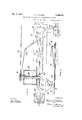
- Fig. l is a si e elevation of a preferred form of mechanism adapted to carry out the. improved process
- Fig. 2 is a plan view showing the type of composite strand produced by the mechamsm
- Fig. 3 is a detail view showinga tensioning means for the metallic foil
- Fig. 4 is an enlarged plan view partly in secion showing details of the mechanism
- Fig. 5 is a longitudinal vertical section showing the formation of the composite strip. 1
- the machine consists of two portions, namely, an assembling portion mounted on a suitable supporting table or the like 2 and a winding portion supported upon a suitable frame 4.
- a spool 6 mounted on frame 2 car- 50 ries a supply cord a of asbestos or other fibrous material which passes from the spool about a pulley 8 whereby it is submerged Within a reservoir 10 carrying either powdered graphite or a liquid or semi-liquid lubricating material.
- the metallic foil passes beneath a tension plate 36 which serves to brace the same against a base plate 37, said tension plate being carried at the free end of a iat spring 38 which is fulcrumed in a slot in a support 40 so that it may be tensioned downwar ly as indicated in Fig 3 by adjustment of a screw 42 which bears upon the spring inwardly of its fulcrum.
- a tension plate 36 which serves to brace the same against a base plate 37
- a tension plate being carried at the free end of a iat spring 38 which is fulcrumed in a slot in a support 40 so that it may be tensioned downwar ly as indicated in Fig 3 by adjustment of a screw 42 which bears upon the spring inwardly of its fulcrum.
- the strip of metallic foil is twisted a out the cord enclosing the graphite, the twisted strip passing through a die provided with a tapering opening 48 serving to compress the composite twisted strip D.
- the rotatable frame 56 is of U-shape, being provided with two arms extending in the direction o f the shaft 50. In one of these arms is located a fixed pin 58, while in the other arm there is located an assembly pin 57 adapted to be detachably-secured in the frame by means of a thumb screw 59.
- a flanged spool 60 is provided with a central aperture in which are receivable the inner ends of pins58 and 57.
- One flange of spool 60 is .arranged to frictionally bear against a collar 62 carried by a pinion 64 rotatably mounted upon pin 58.
- the spool 60 is pressed against member 62 by means of a spring 66 surrounding the assembly pin 57. It will be clear from the above construction that the spool may be relmoved by freeing pin 57 and pulling the same outwardly so as to disengage the pin from4 the aperture in the spool and thereby permit the disengagement of the spool'from pin 58.
- Pinion 64 meshes with la small pinion 67 carried by a transverse shaft journalled in the rotata gear 68 meshin with a bevel gear' 7 O'fixedlyv secured to the ed shaft 50.
- the axis of shaft 50 and the rotatable clutches does not extend in the direction of the opening 48 of the die, but, asindicated in that figure, slopes upwardly in the direction of the assembling mechanism.
- the cord a serves to rotate the screw-conveyor 18 at a definite relative velocit with respect to the cord so-*that an even distribution of graplite in the composite material is obtaine metallic foil about the le frame, which shaft carriesl a bevel
- the composite material will be wound spirally upon the drum until the material approaching the drum contacts with a flange, whereupon the winding will automatically reverse in direction so as to position spirally the composite strip toward the other flange, whereby an evenly wound spool of material will result.
- the material may be cut off and an empty spool substituted.
- the method of making packing material including assembling a strip of metallic foil and a flexible cord, -feeding upon the foil solid lubricating material, 4twisting the metallic foil about the cord and lubricating material, and pressing the foil about the cord.
- a device for makin packing material including means for guidging astrip of me- -tallic foil, means for assembling a flexible.
- a device for makin packing material A including means for gui in a. strip of metallic fo1l,”means for assem ling a flexible cord with the said strip of foil, means for feeding lubricant to the foil, means for twisting the foil about the cord, said last'named means including a rotatable frame, a spool mounted on the frame to rotate about an axis transverse to the axis of rotation of the frame, and means for rotating the spool about its axis during its rotation with the frame.
- a device for making packing material including means for guiding a strip of metallic foil, means for assembling a flexible cord with the s aid stri of foil, means for feeding lubricant to the oil, means for twisting the foil. about the cord, said last named means including a rotatable frame, a spool mounted 'on the frame to rotate about an axis transverse to the axis of rotation of the frame, and means for yieldingly rotating the spool about its axis during its rotation with the frame.
- device for making packing material including means for guiding a strip of metal* lic toil, means for assembling a flexible cord with the said strip of foil, means for twisting the foil about the cord, said last named means including a rotatable trame, a spool mounted on the frame to rotate about an axis transverse to the axis of rotation of the trame, and means for rotating the spool about its axis during its rotation with the trame, the axis ot rotation of the trame sloping relatively to the direction of extent of the twisted strip of packing material approaching the spool.
- a device for making packing material including means for guiding a strip of metallic toil, means tor assembling a flexible cord with the said strip of Jfoil, means operated by the movement ot the cord for feeding lubricating material upon the foil, means Jfor twisting the toil about the cord and lubricating material, and means for yieldingly taking up the twisted product.
- rlhe method ot making packing material including longitudinally progressing a strip ot metallic toil, twisting the strip at one point about an aXis approximately aligned with its direction of progression, the strip being substantially flat and held against rotation at a point in advance of the point of twisting whereby a progressive twist is imparted to the strip, and compacting the foil by inwardly directed pressure between the two said points and duringthe progressive twisting.
- the method of making packing material including longitudinally progressingr a strip ot metallic toil. twisting the strip at one point about an axis approximately aligned with its direction ot' progression, the strip being substantially ilat and held against rotation at a point in advance ot the point of twisting whereby a progressive twist is imparted to the strip, compacting the foil by inwardly directed pressure between the two said points and during the progressive twisting, and applying lubricant tothe strip in advance ot' the compacting operation.
- a device for making packing material including means tor reeling and twisting a strip oi" metallic toil. means fory guiding the strip in substantiallv flat condition towards the reeling and twisting means. and a tapered l die through which the strip passes between the atorementioned means arranged to com? pact the 'toil by inwardly directed pressure, said guiding means maintaining the strips ⁇ tlat at a point substantially in the line ot the airis ot the die.
- ll. l device tor making packing material including means for reeling and twisting a strip ot metallic toil, means tor guiding the strip in substantially flat condition towards the reeling and twisting means, a tapered die through which the strip passes between the aforementioned means arranged to compact the foil by inwardly directed pressure, and means for applying lubricant to the strip in advance of the compacting operation.
- a device for making packing material including means for reeling and twisting a strip of metallic foil, means for guiding the strip in substantially flat condition towards the reeling and twisting means, and means for applying solid lubricant to 'the strip while it is in substantially flat condition, whereby the lubricant is enclosed in the strip during the twisting operation.
Landscapes
- Engineering & Computer Science (AREA)
- General Engineering & Computer Science (AREA)
- Mechanical Engineering (AREA)
- Ropes Or Cables (AREA)
Description
May 2%, WWE. .1. N. WALTQN PROCESS AND APPARATUS FOR MANUFACTURING PCKNG V Filed June 29, 1929 2 Sheets-Sheet l wat? MEW 3 m32 J. N. WALTON 1,856,086
PROCESS AND APPARATUS FOR MANUFACTURING PACKING Filed June 29, 1929 2 Sheets-Sheet 2 MII Patented May 3, 1932 UNITED STATES PATENT OFFICE JULIAN N. 'WALTOIL OF BROOKLYN, NEW YORK, ASSIGNOR TO THE ANCHOR PACKING UOIPANY, F PHILADELPHIA, PENNSYLVANIA, A CORPORATION OF NEW JERSEY PROCESS AND APPARATUS FOR MANUFACTURING PACKING Application filed June 29, 1929. Serial No. 374,926.
This invention relates to a process for manufacturing packing for journal boxes or the like and mechanism for conveniently carrying out the novel rocess.
An adyanta cous orm ot packing for journal bores or similar machine parts is found to consist of a composite material' composed ot" a suitable -cord about 4which, is twisted metallic toil and whichl preferably includes in its construction granules of graphite or other suitable lubricating material.
lt is the primary object of the present invention to produce a composite strand which may be built up into suitable packing meml bers in the form of annular rings or other shapes dependent upon the uses to which the packing is put. The process is primarily de signed to produce a composite strand of this character which is most readily adapted for manipulation to produce such packing in that it is readily worked so as to be braided or wound into final shape.
Further objects of the invention relate to the provision of a mechanism whereby the 95 process may be most advantageously carried out in an automatic fashion so as to produce not only a suitable com osite strand but also to wind up such strand 1n a proper fashion to produce a spool of the composite material.
ln the drawin Fig. l is a si e elevation of a preferred form of mechanism adapted to carry out the. improved process;
Fig. 2 is a plan view showing the type of composite strand produced by the mechamsm;
Fig. 3 is a detail view showinga tensioning means for the metallic foil;
Fig. 4 is an enlarged plan view partly in secion showing details of the mechanism;
Fig. 5 is a longitudinal vertical section showing the formation of the composite strip. 1
The machine consists of two portions, namely, an assembling portion mounted on a suitable supporting table or the like 2 and a winding portion supported upon a suitable frame 4. A spool 6 mounted on frame 2 car- 50 ries a supply cord a of asbestos or other fibrous material which passes from the spool about a pulley 8 whereby it is submerged Within a reservoir 10 carrying either powdered graphite or a liquid or semi-liquid lubricating material. From pulley 8 the cord passes over 'a guiding post l2 and thence about a pulley 16 mounted on the end of a screwconveyor 18 positioned in the lower end of a bin 20 from which it is adapted to supply flaked graphite or similar lubricating material c in a manner'which will be hereinafter described.
From the pulley 16 which the cord a drives in its passage it passes about or through suitable guides 22 and 24 and thence downward ly through an aperture in the end of a ilexible plate 26 carried by a guiding member 28 within which is a slot serving to properly align a strip of metallic foil such as aluminum, ylead or tin foil passing therethrough. This metallic foil is carried by a supply spool 30 on one end of which is mounted a drum about which is trained a belt or cord 32 secured at one end to' the frame and carrying at its other end a weight 34 so as to oifer frictional resistance to unwinding of spool 30 and thereby impose a-tension upon the strip of metallic foil. From the spool the metallic foil passes beneath a tension plate 36 which serves to brace the same against a base plate 37, said tension plate being carried at the free end of a iat spring 38 which is fulcrumed in a slot in a support 40 so that it may be tensioned downwar ly as indicated in Fig 3 by adjustment of a screw 42 which bears upon the spring inwardly of its fulcrum. As the strip of metallfoil b passes beneath the eye in the flexible plate 26 the cord a is located thereover and together they pass through a suitable guiding slot formed in a member 44 carried by the frame and thence below the discharge position of screw conveyor 18 where llaked gra hite or the like is delivered upon theI strip 'and cord.l
Following the delivery of the aphite, the strip of metallic foil is twisted a out the cord enclosing the graphite, the twisted strip passing through a die provided with a tapering opening 48 serving to compress the composite twisted strip D.
sleeve journalled in the frame concentrically with the fixed shaft 50 and carrying a Arotatable supporting frame 56. VThe rotatable frame 56 is of U-shape, being provided with two arms extending in the direction o f the shaft 50. In one of these arms is located a fixed pin 58, while in the other arm there is located an assembly pin 57 adapted to be detachably-secured in the frame by means of a thumb screw 59. A flanged spool 60 is provided with a central aperture in which are receivable the inner ends of pins58 and 57. One flange of spool 60 is .arranged to frictionally bear against a collar 62 carried by a pinion 64 rotatably mounted upon pin 58. The spool 60 is pressed against member 62 by means of a spring 66 surrounding the assembly pin 57. It will be clear from the above construction that the spool may be relmoved by freeing pin 57 and pulling the same outwardly so as to disengage the pin from4 the aperture in the spool and thereby permit the disengagement of the spool'from pin 58. Pinion 64 meshes with la small pinion 67 carried by a transverse shaft journalled in the rotata gear 68 meshin with a bevel gear' 7 O'fixedlyv secured to the ed shaft 50.
As indicated in Fig. 1, the axis of shaft 50 and the rotatable clutches does not extend in the direction of the opening 48 of the die, but, asindicated in that figure, slopes upwardly in the direction of the assembling mechanism.
The operation of the device will be apparent from the above description. During rotation of the frame 56 upon engagement of clutch members 52 and 54, the spool 60 is rotated about the axis of the fixed shaft 50 so as to twist the metallic foil about the cord and graphite. As this twisting proceeds, the
engagement of bevelgear 68 w1th the fixed L bevel gear 70 will cause a rotation of spool 60 about the axis of pins 57 and 58 to take u the twisted composite material. Inasmuc as the spool is merely frictionally driven, the composite twisted material will be taken up only yieldingly so as. not to produce any breaking of the same because of undue tension `resultingfrom stoppaf'e inthe4 assembling mechanism or Kby un ue resistance of the ie 48. As the material is drawn along, the cord a serves to rotate the screw-conveyor 18 at a definite relative velocit with respect to the cord so-*that an even distribution of graplite in the composite material is obtaine metallic foil about the le frame, which shaft carriesl a bevel By the sloping arrangement of the axis of rotation of the frame it is found that the composite material will be wound spirally upon the drum until the material approaching the drum contacts with a flange, whereupon the winding will automatically reverse in direction so as to position spirally the composite strip toward the other flange, whereby an evenly wound spool of material will result.
s soon as one spool is wound, the material may be cut off and an empty spool substituted.
By the above process, which may obviously be carried out by other mechanisms than thatdisclosed or less efficiently by manual operation, there is produced a suitable composite ,strip in which an excess of. metallic foil is present, as indicated in Fig. 2, whereby the same maybe readily flexed in order to be braided, wound or pressed into suitable packing members.
What I claim and desire to protect by Letters Patent is: l f
1. The method of making packing material including assemblinga strip of metallic foil and a flexible cord, feeding upon the foil solid lubricating material, and twisting the cord and lubricating material. j. l
2. The method of making packing material including assembling a strip of metallic foil and a flexible cord, -feeding upon the foil solid lubricating material, 4twisting the metallic foil about the cord and lubricating material, and pressing the foil about the cord.
3. A device for makin packing material including means for guidging astrip of me- -tallic foil, means for assembling a flexible.
cord with the said strip of foil, means o rated by the movement of the cord `for fe mg lubricating material upon the foil, andimeans 4. A device for makin packing material A including means for gui in a. strip of metallic fo1l,"means for assem ling a flexible cord with the said strip of foil, means for feeding lubricant to the foil, means for twisting the foil about the cord, said last'named means including a rotatable frame, a spool mounted on the frame to rotate about an axis transverse to the axis of rotation of the frame, and means for rotating the spool about its axis during its rotation with the frame.
5. A device for making packing material including means for guiding a strip of metallic foil, means for assembling a flexible cord with the s aid stri of foil, means for feeding lubricant to the oil, means for twisting the foil. about the cord, said last named means including a rotatable frame, a spool mounted 'on the frame to rotate about an axis transverse to the axis of rotation of the frame, and means for yieldingly rotating the spool about its axis during its rotation with the frame.
ttl
6. device for making packing material including means for guiding a strip of metal* lic toil, means for assembling a flexible cord with the said strip of foil, means for twisting the foil about the cord, said last named means including a rotatable trame, a spool mounted on the frame to rotate about an axis transverse to the axis of rotation of the trame, and means for rotating the spool about its axis during its rotation with the trame, the axis ot rotation of the trame sloping relatively to the direction of extent of the twisted strip of packing material approaching the spool.
7. A device for making packing material including means for guiding a strip of metallic toil, means tor assembling a flexible cord with the said strip of Jfoil, means operated by the movement ot the cord for feeding lubricating material upon the foil, means Jfor twisting the toil about the cord and lubricating material, and means for yieldingly taking up the twisted product.
8. rlhe method ot making packing material including longitudinally progressing a strip ot metallic toil, twisting the strip at one point about an aXis approximately aligned with its direction of progression, the strip being substantially flat and held against rotation at a point in advance of the point of twisting whereby a progressive twist is imparted to the strip, and compacting the foil by inwardly directed pressure between the two said points and duringthe progressive twisting.
9. The method of making packing material including longitudinally progressingr a strip ot metallic toil. twisting the strip at one point about an axis approximately aligned with its direction ot' progression, the strip being substantially ilat and held against rotation at a point in advance ot the point of twisting whereby a progressive twist is imparted to the strip, compacting the foil by inwardly directed pressure between the two said points and during the progressive twisting, and applying lubricant tothe strip in advance ot' the compacting operation.
lll. A device for making packing material including means tor reeling and twisting a strip oi" metallic toil. means fory guiding the strip in substantiallv flat condition towards the reeling and twisting means. and a tapered l die through which the strip passes between the atorementioned means arranged to com? pact the 'toil by inwardly directed pressure, said guiding means maintaining the strips `tlat at a point substantially in the line ot the airis ot the die.
ll. l device tor making packing material including means for reeling and twisting a strip ot metallic toil, means tor guiding the strip in substantially flat condition towards the reeling and twisting means, a tapered die through which the strip passes between the aforementioned means arranged to compact the foil by inwardly directed pressure, and means for applying lubricant to the strip in advance of the compacting operation.
12. A device for making packing material including means for reeling and twisting a strip of metallic foil, means for guiding the strip in substantially flat condition towards the reeling and twisting means, and means for applying solid lubricant to 'the strip while it is in substantially flat condition, whereby the lubricant is enclosed in the strip during the twisting operation.
In testimony of which invention, I have hereunto set my hand, at New York, on-this 22nd day of June, 1929.
JULIAN N. WALTON.
los
Priority Applications (1)
| Application Number | Priority Date | Filing Date | Title |
|---|---|---|---|
| US374926A US1856086A (en) | 1929-06-29 | 1929-06-29 | Process and apparatus for manufacturing packing |
Applications Claiming Priority (1)
| Application Number | Priority Date | Filing Date | Title |
|---|---|---|---|
| US374926A US1856086A (en) | 1929-06-29 | 1929-06-29 | Process and apparatus for manufacturing packing |
Publications (1)
| Publication Number | Publication Date |
|---|---|
| US1856086A true US1856086A (en) | 1932-05-03 |
Family
ID=23478766
Family Applications (1)
| Application Number | Title | Priority Date | Filing Date |
|---|---|---|---|
| US374926A Expired - Lifetime US1856086A (en) | 1929-06-29 | 1929-06-29 | Process and apparatus for manufacturing packing |
Country Status (1)
| Country | Link |
|---|---|
| US (1) | US1856086A (en) |
-
1929
- 1929-06-29 US US374926A patent/US1856086A/en not_active Expired - Lifetime
Similar Documents
| Publication | Publication Date | Title |
|---|---|---|
| CN114204762A (en) | Winding processing device for motor stator coil | |
| US1856086A (en) | Process and apparatus for manufacturing packing | |
| US2366087A (en) | Machine for making tubular structures | |
| US1953502A (en) | Method of and mechanism for producing helical coils | |
| US1684511A (en) | Strand-twisting apparatus | |
| US2284321A (en) | Apparatus for making paper cord | |
| US1976821A (en) | Apparatus for manufacturing armored conductors | |
| US2430358A (en) | Material serving apparatus | |
| US1793487A (en) | Apparatus for making electric cables | |
| US1616068A (en) | Wire-covering machine | |
| US1734704A (en) | Method of and apparatus for unwinding strand material | |
| US2505050A (en) | Apparatus for making paper cord | |
| US621735A (en) | Machine for | |
| US2248572A (en) | Apparatus for making ornamental articles | |
| GB495255A (en) | Improvements in the manufacture of wire strands | |
| US3837152A (en) | Rope-twisting machine | |
| US1645884A (en) | A corpo | |
| US2153409A (en) | Machine for making golf balls | |
| US1461816A (en) | Wire-covering machine | |
| US1388428A (en) | Machine for making packing | |
| US1554679A (en) | Apparatus for insulating electric conductors | |
| DE1048305B (en) | Winding drum, the braking effect of which is regulated by the weight of the drum, in particular for rope-like winding material for electrical cables | |
| US1576577A (en) | Wire-covering machine | |
| US2062061A (en) | Method of incorporating lubricant | |
| US1789881A (en) | Machine for making insulated wire |